7.5 Control Code
7.5.1 LF
1.Line Feed Command
2.Hexadecimal Data <DA> H
3.Function
If characters are stored in the printer line-buffer when command LF is received, they
are printed and carriage returns. If not, the paper is fed one line and carriage returns.
7.5.2 FF
1.Form Feed Command
2.Hexadecimal Data <DC> H
3.Function
When command FF is received, characters stored in the printer line-buffer are printed;
the paper is fed approximate 30 mm and carriage returns.
7.5.3 SO
1.Shift out Command
2.Hexadecimal Data <DE> H
3.Function
When command SO is received, the mode is set in 20 characters/line. The character
data following this code are printed as enlarged characters until command DC2 is re-
ceived. If SO is received in enlarged mode, this command is ignored.
7.5.4 SI
1.Shift in Command
2.Hexadecimal Data <DF> H
3.Function
When command SI is received, the mode is set in 80 characters/line. The character
data following this code are printed as condensed characters until command DC4 is
received. If SO is received in enlarged mode, this command is ignored.
7.5.5 DC1
1.Device Control 1 Command
2.Hexadecimal Data <11> H
3.Function
When the printer buffer is stored less than quarter after sending command DC3, the
printer send command DC1 to the host. This command DC1 cancels the mode of com-
mand DC3.
7.5.6 DC2
1.Device Control 2 Command
2.Hexadecimal Data <12> H
3.Function
When command DC2 is received, the printer cancels the enlarged mode. The character
data following this code are printed as normal characters (40 characters/line)
7.5.7 DC3
1.Device Control 3 Command
2.Hexadecimal Data <13> H
3.Function
When the printer buffer is stored more than three quarters, the printer sends com-
mand DC3 to the host. After the host receives command DC3, the host may not send
data to the printer.
7.5.8 DC4
1.Device Control 4 Command
2.Hexadecimal Data <14> H
3.Function
When command DC2 is received, the printer cancels the condensed mode. ACSII data
following this code are printed as normal characters (40 characters/line)
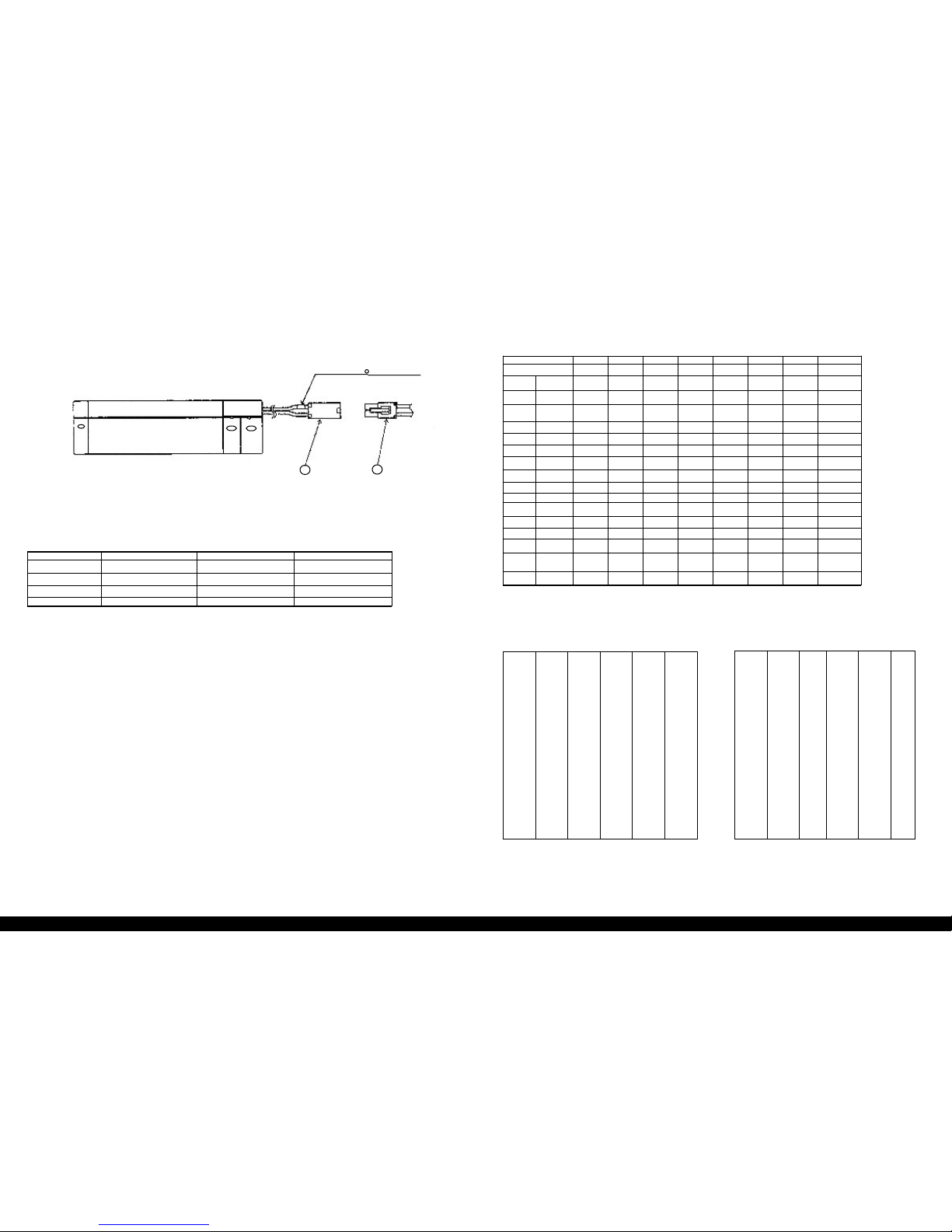
7.6 Identity of Printer
Request from the host by command : ESC [0c.Hexadecimal<1B,5B,30,63>H
Answer from the printer : ESC JB2151A. Hesadecimal<1B,4A,42,32,3
1,35,31,41>H
7.7 Non-Dened Code
If non-dened code is received, it is ignored.
7.8 Printing start
When the printer completes the receiving of a line data, it starts printing. When the
printer cannot complete the receiving, and if the data is not transmitted for 5 seconds,
it starts printing.
7.9 Limit Temperature for Printing
When the temperature of the thermal head is more than approximate 74 C°, the prin-
ter stops printing and blinks the ERROR-LED. When the temperature of the thermal
head falls less than approximate 71 C°, the printer resumes printing.