Manson Engineering Industrial SBC-5926 User manual

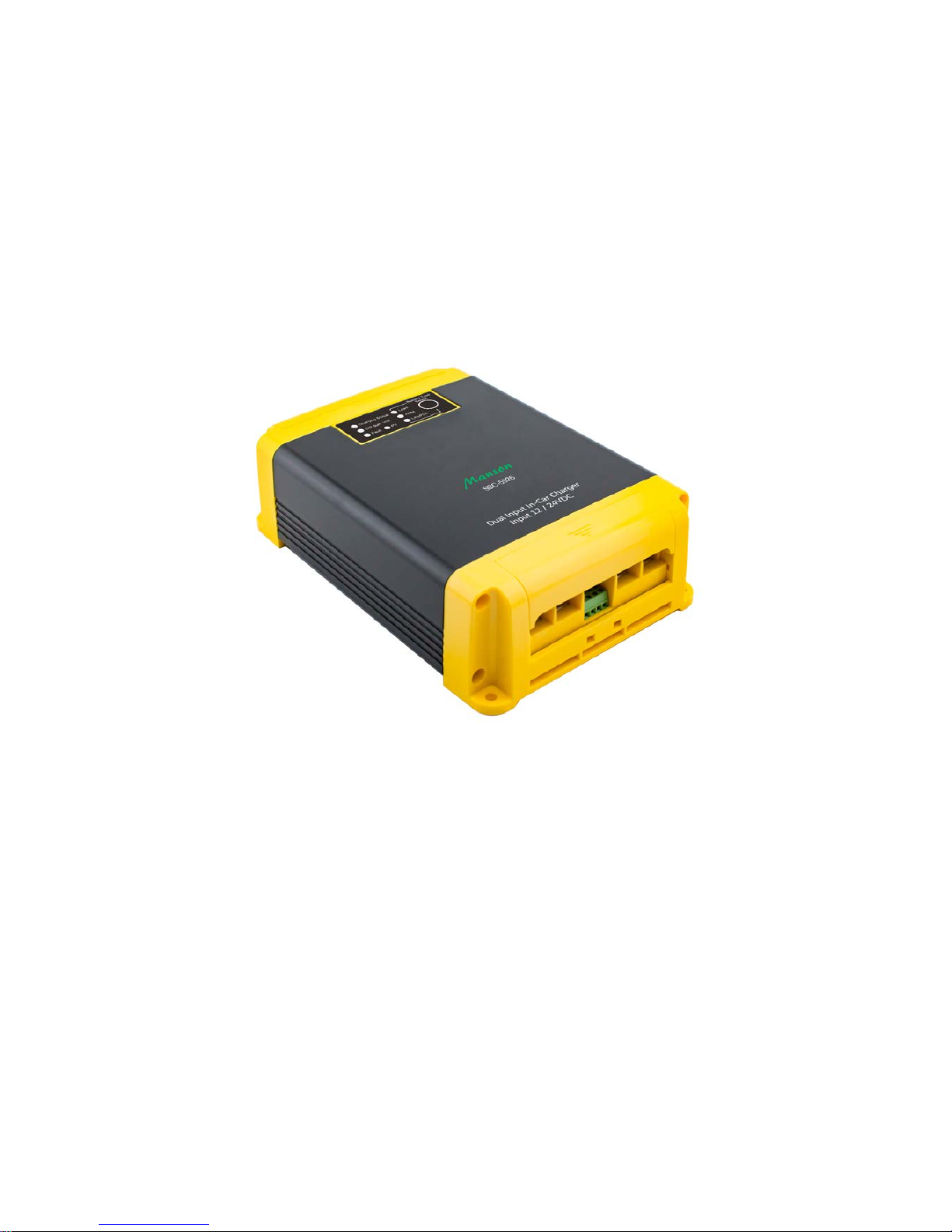
SBC-5926
12V In-Car Charger
Dual Input (Solar MPPT & DC)
Operation manual
Keep this manual in a safe place for quick reference at all times.
This manual contains important safety and operation instructions for correct use of the battery charger.
Read through the manual and pay special attention to the markings and labels of the charger,
battery and equipment connected to the battery system.
Pay special attention to these two types of notices used in this manual.
Failure to heed this warning may cause injury to persons and damage to Equipment.
Failure to observe this warning may result in damage to equipment
and improper functioning of the Charger.
WARNING:
●The charger is not designed for any life saving application.
●The charger is designed for in-door use. Protect the charger from ingress of water.
●This charger is made to charge only properly sized lead acid batteries and Lithium Fe PO4 (LFP).
●Don't recharging non-rechargeable batteries.
●Charging other types of battery or under-sized lead acid batteries may cause fire or explosion.
●Install the charger in accordance with all local codes.
●Do not use the charger if it has been dropped or damaged.
●Do not remove casing of the charger, there is no user -serviceable parts inside.
●Do not charge the battery on boats. Remove the battery and charge on shore.
●Never attempt to charge a frozen battery.
●Never attempt to charge a damaged battery.
●Wear protective goggles and turn your face away when connecting or disconnecting the battery.
●Never place the charger on top of a battery.
●Never smoke, use an open flame, or create sparks near battery or charger during normal charging
operation as batteries may give out explosive gas.
●Do not charge batteries in an enclosure (box- in) due to possible explosion of entrapped explosive gas.
●Use of accessory not recommended may cause risk of fire, electric shock.
●Disconnect the mains supply before connecting or disconnecting the links to the battery.
●If the charger does not work properly or if it has been damaged, unplug all DC connections.
Copy Right
All rights reserved.
No part of this publication may be reproduced, or transmitted in any form or by any means without the written
permission from Manson Engineering Industrial Ltd.
Changes in the manual.
Manson Engineering Industrial Ltd. has the right to update and change the content of this manual without
any prior notice and obligation.
Disclaimer
Exclusions for documentation, Indemnity and Product application.
Manson Engineering Industrial Ltd. (Manson)
1) Assumes no warranty to the accuracy, suitability of technical information given in the user manuals or
other documentation.
2) Undertakes no responsibility or liability of losses, damages and related expenses whether specific,
direct, indirect consequential or accidental which might result from the use of information given in this
manual.
3) Shall not be liable to anyone for any special, collateral, incidental or consequential damages in
connection with or from the use of these Manson products. The sole and exclusive liability to Manson,
regardless of the form of action shall not exceed the purchase price of the Manson product.

Table of content
Induction P.4
Features P.5
Self Recoverable Protections P.5
Supplied Accessories P.5
Installation Procedure P.6
Battery Type Selection P.7
Solar panel and DC source Dual inputs P.7
Factory Preset Mode, Ignition Feed Mode & Vibration Sensor Mode P.7
To Set Ignition Feed of the charger to AUTO-ON P.8
To Set Ignition Feed of the charger to Manual ON-OFF operation P.8
How to deactivate the Ignition Feed ON mode P.8
Enable build-in vibration sensor P.8
Over ride of Ignition control by vibration sensor P.8
Indicators and Controls P.8-9
Connection P.9
Connect & Wiring Diagram P.10
Specification P.11
Troubleshooting P.12
Figure index
Fig. 1 correct installation direction P.6
Fig. 2 showing 7 LEDs indicators and one SET button P.8
Fig. 3 Terminals & 8PIN connector P.9
Fig. 4 Connection Diagram P.10

Introduction
Especially designed for vehicles with Smart Alternator , Start-Stop ,Regenerative Braking system
The SBC-5926 is designed to address to the issues of wide swing of output voltages from the smart
alternator, braking regenerative EURO 5/6 vehicles in fully charging the house battery. It is suitable for use
with all old alternator system and distant house battery.
The built-in vibration sensor makes it possible to use the charger by just connecting to the starter battery
terminal without touching the car’s electrical /electronic wiring thus avoiding any possible excuse of revoking
the car’s warranty.
The digital control and auto-select design of SBC-5926 make it automatically adapt to 12V or 24V input
alternator/ battery system.
This is an automatic dual input solar & alternator-battery charger for charging 12V house battery banks of
lead acid , AGM type II and Lithium Fe Po4 batteries.
The built in Solar charge controller is of Maximum Power Point Tracking (MPPT) technology which
maximizes the PV power from your 12V up to 20 Amp or 400 Watt solar panels to your house battery.
In 12V alternator /battery system the house battery is charged by both Solar and alternator /battery
simultaneously to maximize the free solar energy.
**In 24V alternator /battery system the house battery is charged by Solar only when the car’s
alternator/battery stops charging operation.
Multistage Charging Process
This is a select (battery type) and forget charger designed for fast and accurate recharge of your deep cycle
house battery. The smart multistage charging enables the charger to be connected permanently to your
battery banks without the worry of over charging or drying out the electrolyte.
Also with both inputs permanently connected, you can be rest assured of charging your batteries whenever
you are on the move or when the sun shines on your solar panel.
Lead Acid Based Battery
A 3 Stage Bulk, Absorption & Float charging profile with maximum constant charging current at the Bulk
Stage and a Constant Voltage with decreasing charging at the Absorption Stage and a reduced voltage Float
Charge for maintenance when battery is full.
LiFePO4 (LFP) Battery
A 2 Stage charging is specially for the LiFePO4 battery and charging current stops at the end of Absorption
Stage.
There are 3 alternator charging modes available, Factory Preset Mode, Ignition Feed Mode, and Vibration
Sensor Mode. When the Vibration Sensor detects vibration from car’s engine, it triggers charging by
alternator.
P.4
Features
●Dual input from car battery with alternator input and Solar panel.
●Auto select for 12V or 24V car system.
●Design all alternators, conventional, smart alternators, start-stop & regenerative braking.
●3 DC Charge Modes to select:
Vibration Sensor Mode.
Ignition Feed Mode with Automatic or Manual Control setting.
Factory Preset Mode (charging function always on).
●Suitable for standard Lead Acid, AGM and Lithium Fe PO4 battery.
●3 Stage charge for Lead Acid based batteries.
●Specific 2 Stage charge for LiFePO4 battery.
Self Recoverable Protections
Input & Output reverse polarity.
Input Under Voltage.
Input & Output Over Voltage.
Over Load.
Charger Over Temperature and cooling fan jammed.
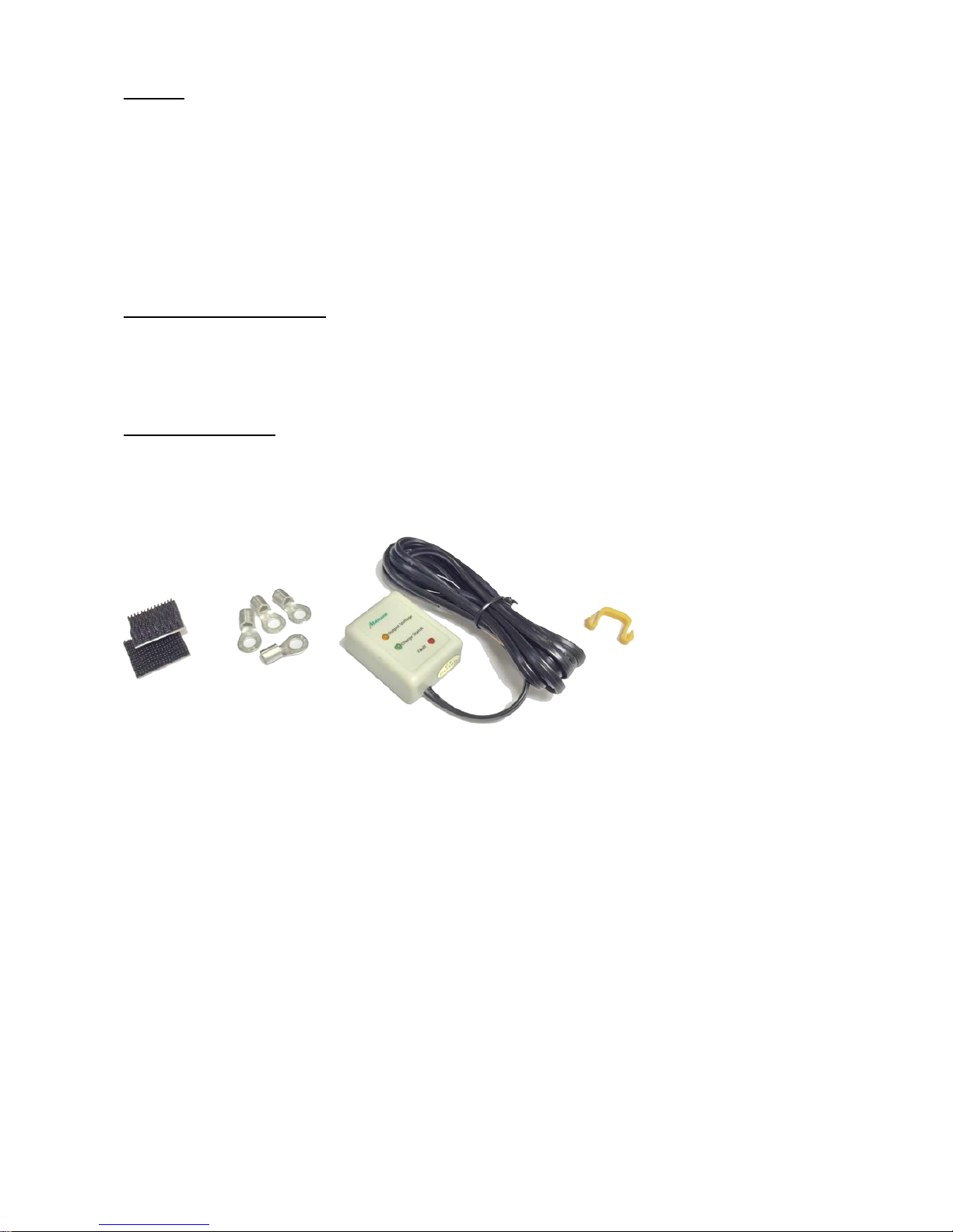
Supplied Accessories
●Remote LED Indicator Module (with 2M cable) like the unit front panel.
●4 heavy duty electrical eye connectors.
●One plastic wire guide.
●Double side sticker tape for the Remote Indicator Module.
P.5
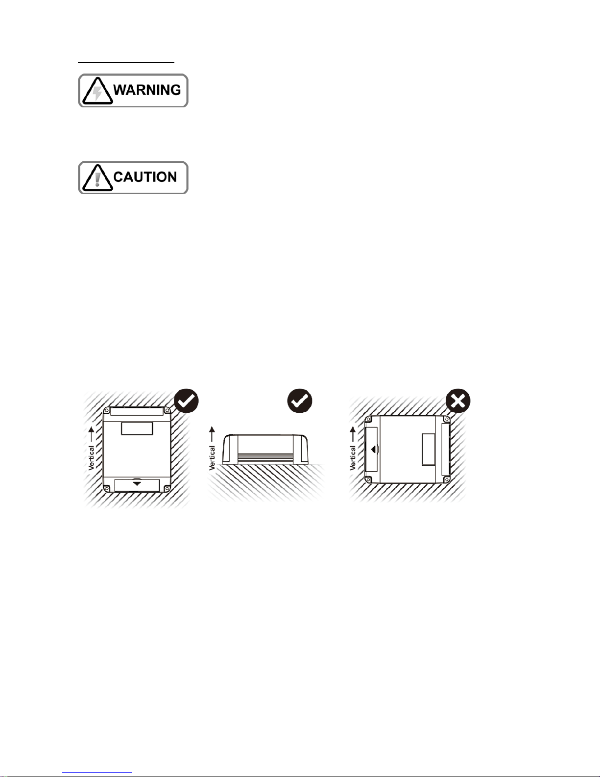
Installation Procedure
Do NOT install this unit in the vehicle engine bay.
This is a fan cooled electronic device not for use in high temperature, corrosive and dusty environment which
will drastically shortens the life and performance of the charger.
This charger is designed only for internal mounting and away from direct sunlight, heat and rain. Allow at
least 80mm of space at both ends for ventilation.
We recommend wiring by a qualified automobile electrician to ensure local safety and on-board standard are
followed
1. To provide the best cooling effect, mount the unit in vertical position with the terminal end facing
downwards due to the top front exhaust design.
2. First install the charger as close to the house battery as possible via a fuse.
3. Check the LED indicators by a few presses on the Select Button.
4. Before connect input to DC Alternator, check on type of alternator of car, for new car with smart
alternator select ether Vibration Sensor Mode or Ignition Feed Mode.
*see table “Summary of 3 operation modes” on next page for detail
Fig.1 correct installation direction
P.6
Battery Type Selection
1. Press and hold the only Set Button for about 5 seconds until the LED flashes.
2. Light quick presses will move the LED from Lead--> AGM--> LiFePO4--> Lead.
3. Stop at the chosen battery type and wait till LED stops flashing to confirm your selection.
Solar panel and DC source Dual inputs
The charger support 12V Solar panel and DC source inputs. Both inputs can be connected simultaneously to
the charger or either one. Charger uses Solar energy as priority source to charge battery to maximize the
usage of Solar panel. The PV LED and charging output will be switched ON whenever the Solar panel has
sufficient energy for charging. The PV LED will ON to indicate Solar panel has sufficient energy and is being
used for charging. During Solar panel being used, no matter single input or dual inputs configure, the Ignition
Control and the Vibration Sensor have NO effect on output ON/OFF control.
*The allowable maximum power rating of solar panel is 400 Watt with maximum 30V Open Circuit voltage.
Factory Preset Mode, Ignition Feed Mode & Vibration Sensor Mode
There are three operation modes for the charger:
1. The charger comes in with the factory default mode:
Ignition control and Vibration Sensor are deactivated, it starts operation
when output and inputs are set up.
This mode will limit the input voltage range to protect over discharge of car’s battery.
This mode is not recommended for modern cars.
2. The Ignition Feed Mode requires wiring connection to the car’s electrical circuit, charger only
operates when car’s ignition has tuned on.
3. The Vibration Sensor Mode over rides the Ignition Feed Mode. It turns on the charger when
vibration is detected, vibration can come from the car’s engine and road.
**Use of vibration sensor does not touch the car’s electrical circuit and avoid problem in car’s
warranty.
Summary of 3 operation modes
CHARGE MODE
12V CAR
24V CAR
CHARGE ON
CHARGE OFF
CHARGE ON
CHARGE OFF
Vibration Sensor Mode
when sensor is triggered by vibration
from car
11-16V
<9V
22-32V
<18V
Ignition Feed – Automatic Mode
connect to Ignition switch when
Ignition is on
11-16V
<9V
22-32V
<18V
Factory Preset Mode
Vibration Sensor & Ignition Feed
Inactive
12.8-16V
<12.2V
25.6-32V
<24.4V
The Ignition Feed and Vibration Sensor modes are suitable for Constant Voltage Alternators, Smart
Alternators, Start Stop, Euro 5 and 6 engines, cars with Regenerative Braking.
P.7

To Set Ignition Feed of the charger to AUTO-ON
Connect the Ignition Pin (in Fig.4: Terminals & 8 Pin Connectors diagram) to the car’s hot wire (that is the
wire that has a positive dc 9 to 32V when car’s ignition is turned on).
The charger only operates when the car is running, and charger stops charging once ignition is off.
To Set Ignition Feed of the charger to Manual ON-OFF operation
You can wire up a push switch with one end to the Vout for Ignition Pin and the other to Ignition Pin, see
Fig.4 Terminals & 8 Pin Connectors diagram. Shorting both pins will turn on the charger, disconnect will turn
off the charger.
How to deactivate the Ignition Feed mode
The Ignition Feed Mode will stay with the charger it has been activated once, even if the charger is taken out
from the system and re-installed in another car. That is once the Ignition Feed Mode has been activated,
charger will only be turned on when there is a positive voltage (+9V to +32V) at the Vout for Ignition Pin,
otherwise the charger stays in off mode.
Reset charger to factory default state with Ignition Feed in deactivated mode, such that the charger will start
charging the house battery as soon as input and output connections are made.
To deactivate the Ignition Feed mode:
1. Disconnect any wire to the Ignition Pin in the charger.
2. Press and hold Set Button for about 15 seconds until 3 battery type LED flash.
3. Release button to complete the deactivation of the Ignition Feed Mode.
Enable build-in vibration sensor
The built-in vibration sensor is enabled by connecting the T+ pin to Vout for
Ignition pin. The vibration sensor is in standby mode with output is OFF (no
charging). When sensor is triggered by vibrations which cause it to go the
active mode and after 8 seconds of further vibrations. The output will be
switched ON for about 100 seconds continuously.
Any further vibration during the 100 seconds active mode, will extend the
output ON for another 100 seconds. The output will be switched OFF if no
more vibration within 100 seconds of last vibration.
Over ride of Ignition Feed by Vibration Sensor
Built-in vibration sensor when enabled dominates the control of output and over rides all other Modes
including the Ignition Feed. That is only vibration can make the charger start charging with output ON.
To disable the Vibration Sensor: Take out the connection between the T+pin from Vout for Ignition pin.
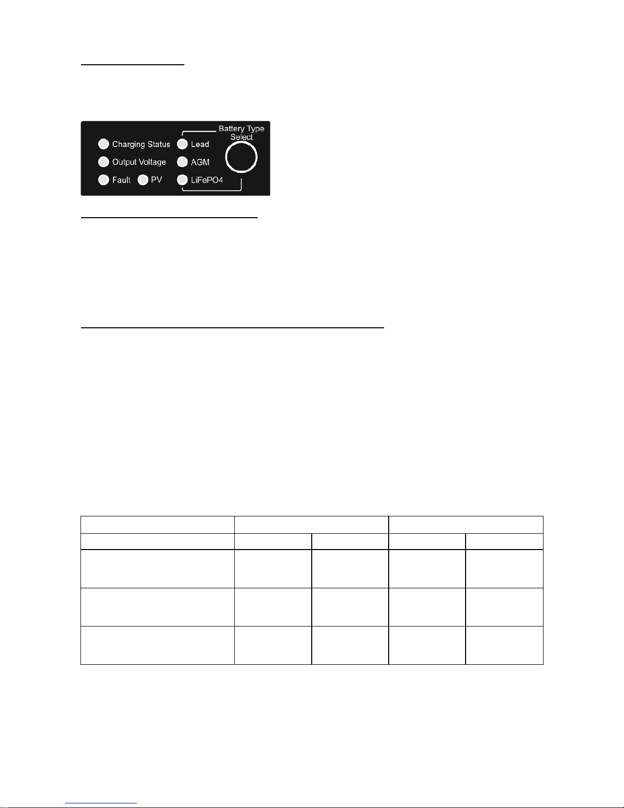
Indicators and Controls
Fig. 2 showing 7 LEDs indicators and one SET button
P.8
Charging Status LED for LEAD ACID Battery - 3 Stages
Charging status LED
Charging stage
Fast flashes
Bulk charge
Slow flashes
Absorption
Solid
Float
Charging Status LED for Lithium Fe PO4 Battery - stages
Charging status LED
Charging stage
Fast flashes
Bulk charge
Slow flashes
Absorption
Output Voltage LED
This LED shows the voltage level at the V OUT terminal, it is the battery voltage when there is no Load
connected to the battery.
LED status
Battery Voltage Level
Fast Flashes
Battery Voltage lower than 12.5V
Slow Flashes
Battery Voltage between 12.5V and 13.6V
Solid
Battery Voltage higher than 13.6V
PV LED
The PV LED is lit when PV panel with over 14.4V output voltage is connected. This is a good way to check
for open circuit in the solar connection. PV LED is off at night.
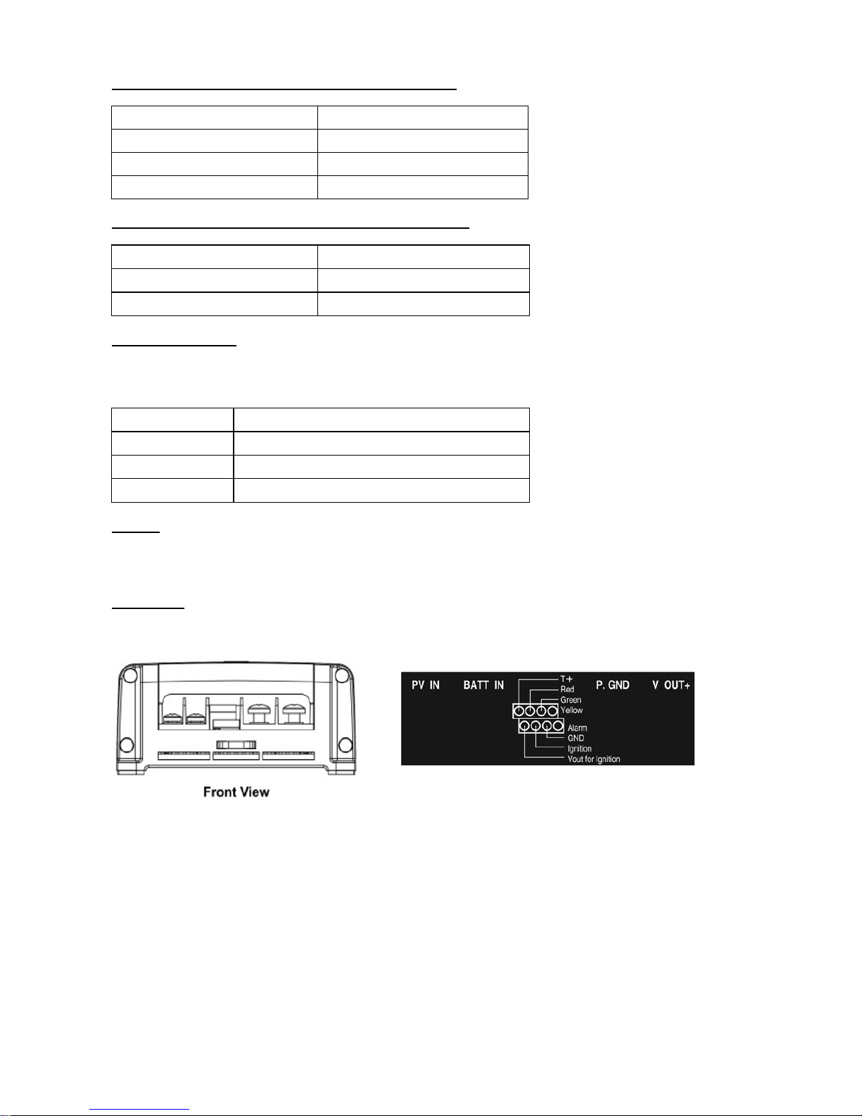
Connection
After both input and output are connected, the charger will have output after 10Sec.
Fig.3 Terminals & 8PIN connectors
1 Vout for Ignition:12 Voltage signal. Short this pin to Ignition pin to enable ignition control of unit.
Short this pin to T+ to enable vibration sensor.
*This pin is for Ignition and Vibration sensor only. Don’t connect to other devices.
2 Ignition: Connect this pin to ignition car ignition to make the charger operate in sync with
vehicle ignition control.
3 GND: Ground pin for remote module. Connect to remote control black wire.
4 Alarm: Alarm output pin. 12V 50mA for external alarm.
5 Yellow: Connect to remote module yellow wire.
6 Green: Connect to remote module green wire.
7 Red: Connection to remote module Red wire.
8 T+: Vibration sensor enable pin. Connect to Vout for Ignition pin to enable Vibration
sensor. P.9
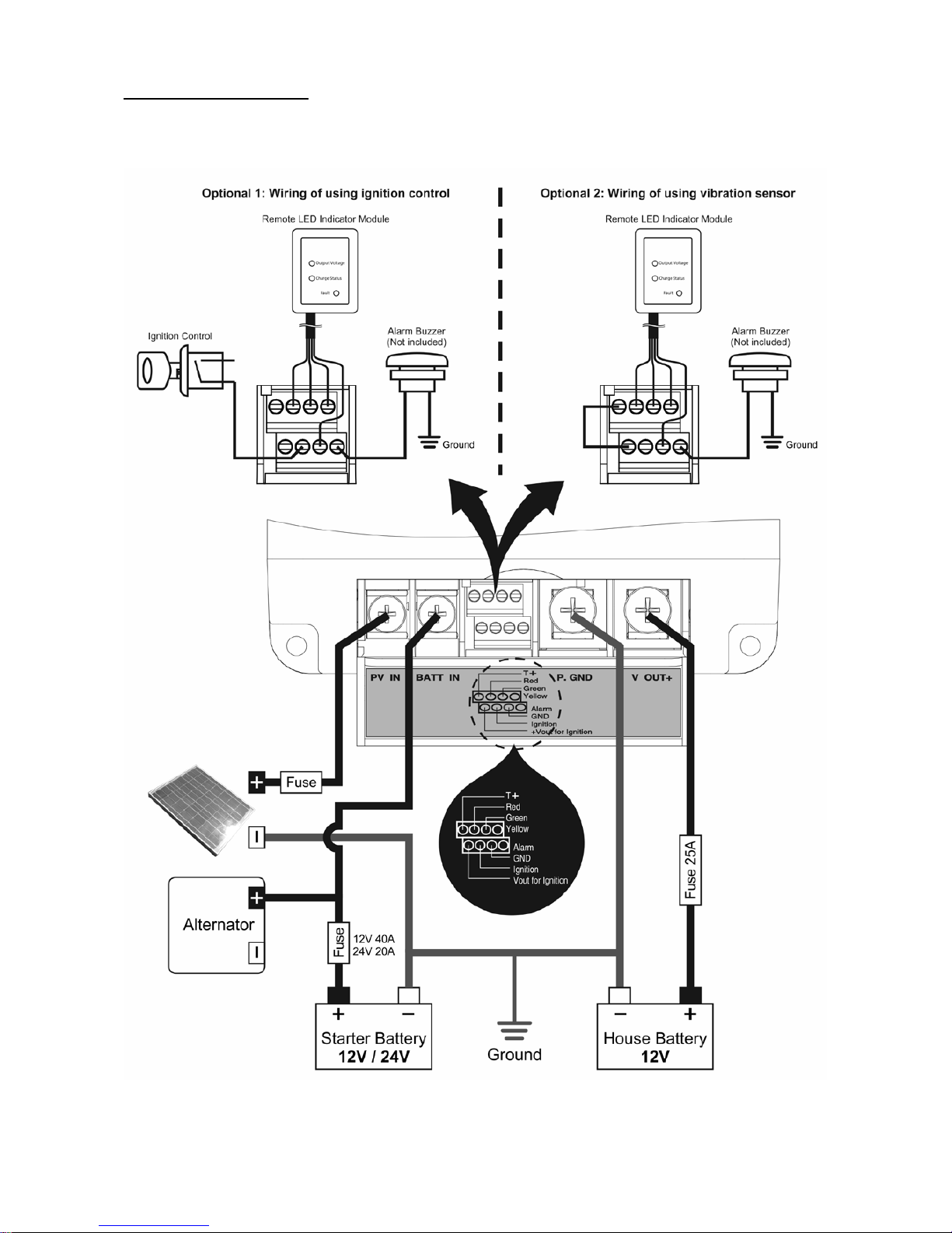
Connect & Wiring Diagram
Individual fuse/ breaker is required to be close to starting battery (charger input) and close to house battery
(charger output wire). Fuse at the solar panel to the rating of the short circuit current of the solar panel.
Fig.4 Connection Diagram
P.10

Specification
Rated output power
20A at 13.8VDC
Efficiency
≥90%
Input Voltage
DC Input Voltage Range
9 - 16VDC (12VDC Input) / 18 - 32VDC (24VDC Input)
Max. Solar Panel Open Circuit Voltage
30VDC
No load input current
<25mA
Output (Charge) Voltage
Battery Type
Absorption
Float
Lead
14.4V
13.3V
AGM
14.7V
13.6V
LiFePO4
14.8V
Stop
Alarm Output
12V / 50mA
Size(L x W x H)mm
130 x 188 x 55mm
Weight
Approx. 870g
Operating Temperature
-10 to +40ºC (Ambient Temperature)
Recommended Cable Size
Cable Length
Recommended SAE
1 – 5 Meters
8AWG
5 – 9 Meters
6AWG
Operating Mode
12V CAR
24V CAR
Vibration Sensor Mode
Charge ON
11-16V
Charge OFF
<9V
Charge ON
22-32V
Charge OFF
<18V
Ignition Feed – Automatic Mode
Charge ON
11-16V
Charge OFF
<9V
Charge ON
22-32V
Charge OFF
<18V
Factory Preset Mode
Charge ON
12.8-16V
Charge OFF
<12.2V
Charge ON
25.6-32V
Charge OFF
<18V
Recommended PV Panel Size
PV Panel Size
400Watt with maximum 30V open circuit voltage
P.11

Trouble Shooting
The Fault LED is solid on when a protection is triggered and output of the charger is off. When the cause of
the fault has been clear up, Fault LED becomes off and charger returns to normal operation. Almost all the
protections are by software design and self recoverable, once the cause of fault has been dealt with. There
are two layers of protection for Input and Output Over-Voltage, the first layer is by software and the second
layer by hardware as a double insurance to protect the charger and the connected devices.
Problem
Indication
Possible Causes
Suggested Solution
Recovery Condition
Low Voltage
Disconnect (LVD)
Ignition Control is not
set to Auto ON
Fault LED ON
12V battery system:
Input voltage <12.8V for
20s.
Check the starter
battery voltage.
Use correct size cable
between charger and
starter battery.
12V battery system:
Automatic recovery
when input voltage
rises above 13.4V for
60s.
Fault LED ON
24V battery system:
Input voltage <25.6V for 20s
24V battery system:
Automatic recovery
when input voltage
rises above 26.8V for
60s.
Low Voltage
Disconnect
(LVD)
Ignition Control is set
to
Auto ON
Fault LED ON
12V battery system:
Input voltage <9V for 5s
Check the starter
battery voltage.
Use correct size cable
between charger and
starter battery.
12V battery system:
Automatic recovery
when input voltage
rises above 11V for 5s.
Fault LED ON
24V battery system:
Input voltage <18V for 5s
24V battery system:
Automatic recovery
when input voltage
raise above 22V for 5s.
Output Over Voltage
Protection (Output
OVP)
Two layers of
protection
First layer by software
Second layer by
hardware
Fault LED ON
Software OVP:
Output terminal voltage >set
absorption Voltage +0.6V
for 2s.
Disconnect any load to
battery and check
battery voltage.
If no load connected to
battery in first place.
Check battery voltage
if over set absorption
voltage, disconnect
battery.
Software OVP:
Automatic recovery
when the voltage on
output terminal is
reduced below
absorption Voltage
+0.3V for 3s.
Fault LED ON
Hardware OVP:
Output terminal voltage
>17.0V.
FUSE will blow.
Hardware OVP:
Does not automatic
recovery
Required to replace the
blown FUSE.
Input Over Voltage
Protection (Input OVP)
Two layers of
protection
First layer by software
Second layer by
hardware
Fault LED ON
PV LED may
also be on at the
same time.
Software input OVP:
Charger output will be
shutdown when input DC
voltage higher than 32V.
Check input battery
voltage is not higher
than 32V.
Software Input OVP:
Automatic recovery
when the voltage on
input terminal is
reduced below 31.5V
for 5s.
Input Over Voltage
Protec
tion (Input OVP)
by hardware.
All LEDs OFF
including the
FAULT LED.
Hardware Input OVP:
The FUSE will blow when
input terminal
voltage higher
than 33.5V.
Find out about the
Input source condition
& spec such as
voltage surge etc.
Before replacing with
the new fuse.
Hardware input OVP:
Does not automatic
recovery
Required to replace the
blown
FUSE.
Over Temperature
Protection (OTP)
Fault LED ON
Charger internal
temperature is too high.
Check input & exhaust
ends have no
blockage and
a minimum 10mm
clearance.
Automatic recovery
when charger
temperature reduce to
normal level.
FAN fault
Fault LED ON
FAN not working
Check for objects
jamming fan or Fan is
out of order.
Remove objects which
jamming
the fan .
REV.3 20180928
7673-5926-0562
P.12
Table of contents
Other Manson Engineering Industrial Automobile Accessories manuals

Manson Engineering Industrial
Manson Engineering Industrial SBC-5925 Installation manual

Manson Engineering Industrial
Manson Engineering Industrial SBC-6104 User manual

Manson Engineering Industrial
Manson Engineering Industrial SDC-6203 User manual

Manson Engineering Industrial
Manson Engineering Industrial SDC–5203 User manual
Popular Automobile Accessories manuals by other brands


ULTIMATE SPEED
ULTIMATE SPEED 279746 Assembly and Safety Advice

SSV Works
SSV Works DF-F65 manual

ULTIMATE SPEED
ULTIMATE SPEED CARBON Assembly and Safety Advice

Witter
Witter F174 Fitting instructions

WeatherTech
WeatherTech No-Drill installation instructions

TAUBENREUTHER
TAUBENREUTHER 1-336050 Installation instruction