Maono AU-WM730 User manual
+
AU-WM730
User Manual • Uživatelský manuál •
Užívateľský manuál •Használati utasítás •
Benutzerhandbuch

2
Dear customer,
Thank you for purchasing our product. Please read the following instructions carefully before
first use and keep this user manual for future reference. Pay particular attention to the safety
instructions. If you have any questions or comments about the device, please contact the
customer line.
✉www.alza.co.uk/kontakt
✆+44 (0)203 514 4411
Importer Alza.cz a.s., Jankovcova 1522/53, Holešovice, 170 00 Praha 7, www.alza.cz

3
Caring for Your Microphone
•Please keep the product in a dry, clean, dust-free environment.
•Keep corrosive chemicals, liquids and heat source away from the product to prevent
mechanics damage.
•Use only a soft and dry cloth for cleaning the product.
•Malfunction may be caused by dropping, impact of external force.
•Do not attempt to disassemble the product. Doing so voids warranty.
•Please have the product checked or repaired by authorized technicians if any
malfunctions happened.
•Failure to follow all the instructions may result in mechanics damage.
•Warranty does not apply to human errors.
Introduction
AU-WM730 wireless microphone system is an equipment in which the audio signal can be
transmitted without wire by using UHF frequency. The system consists of two parts: portable
transmitter and receiver. By using it, the audio signal can be transmitted and received within
100 meters to avoid the inconvenience caused by the long wire between microphone and the
camera. It’s wireless and convenient so that it is ideal solution for long distance audio
recording, filming and interview.
The packing includes a omnidirectional microphone, a 3.5mm to 3.5mm TRS audio cable, a
3.5mm TRS to 3.5mm TRRS audio cable and a camera cold shoe mount.
Product features
•Independent transmitter & receiver
•48 UHF channels
•Large LCD
•Low cut filter
•Attenuator
•Mute
•Transmission range up to 100 meters (328 ft)
4
Communication frequency
570.0 MHz –593.5 MHz
Number of Channels
48
Frequency Response
40 Hz to 18 kHz (+/- 3dB)
Working Range
Up to 100 meters (328 ft)
Antenna Type
External
Audio Input Interface
3.5 mm Line-in
Signal to Noise
>= 70 dB
Distortion
<= 0.2%
Headphone Output
40 mW (32 V/1kHz THD + N + 1 %)
Audio Output Level
+5 dB +/- 2 dB
Power Supply
AA ×2
Battery Life
Around 6 h
Size (antenna included)
218 (H) ×63 (L) ×24 (W) mm
Weight
90 g
Product & Accessories
Portable receiver
Portable transmitter

5
Omnidirectional tie-clip microphone
Audio output cable
Smartphone audio input cable
Microphone tie clip
Sponge
Belt clip
Cold shoe mount
6
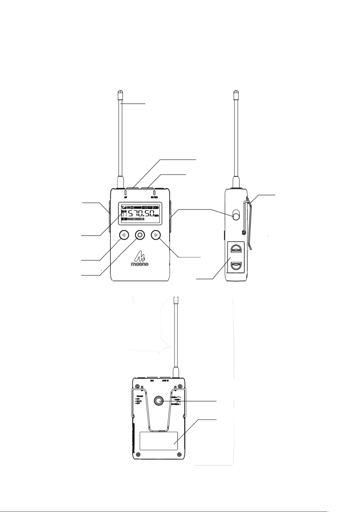
Buttons & interface
Transmitter
Antenna
External audio input
Lavalier interface
Attenuation / low
cut / normal
Display
Left button
Function key
Back clip
Power switch/mute
Right button
Battery holder
Front side
Right side
Back Side
Product label
Bracket interface
(1/4, threats)
7
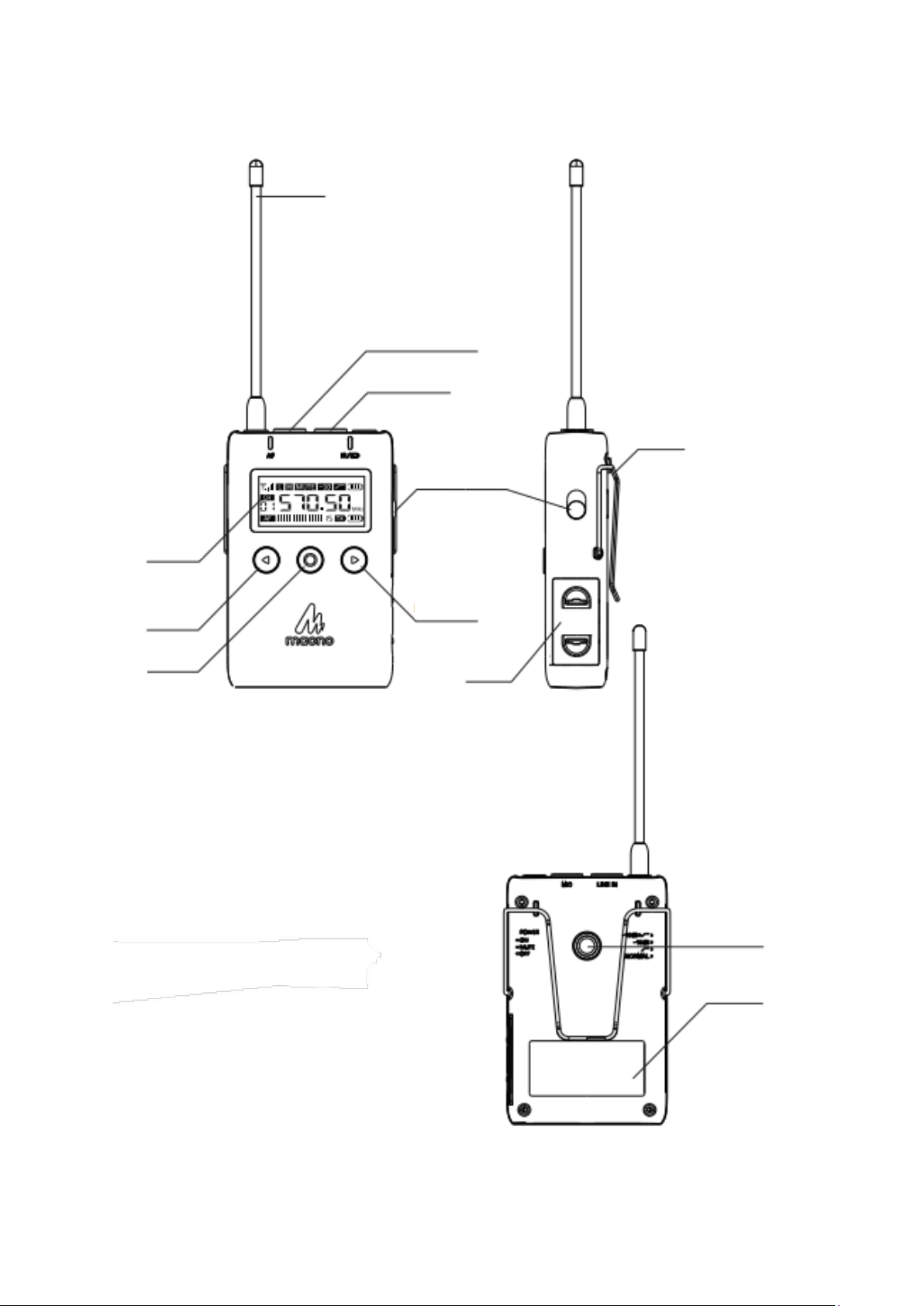
Receiver
Antenna
Real-time receive and
output interfaces
Audio output
Display
Left button
Function key
Power switch /
mute
Back side
Right button
Battery holder
Front side
Right side
Bracket interface
(1/4, threats)
Product label
Back side

8
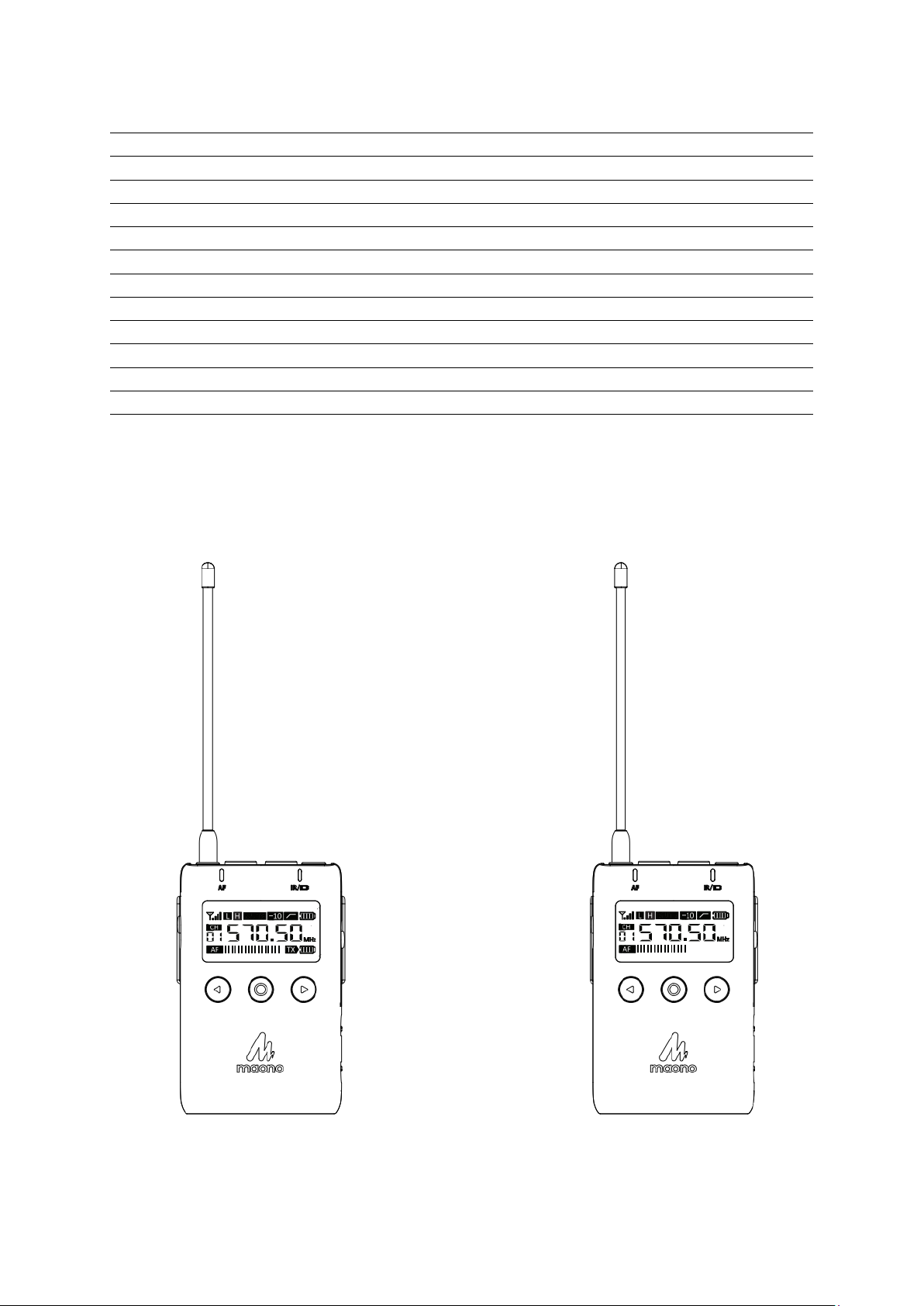
LCD display introduction
Transmitter display
Receiver display
Power: H/L
Mute
Attenuate
Low-Cut
Battery level
Signal
status
Voice level
display
Voice level display
Frequency display
Mute
Battery level
Signal
status
Channel
Frequency
display
VOL display
Voice level display
Battery level of
transmitter

9
Battery installation
Both the transmitter and receiver are powered by two AA batteries. To install the battery,
please follow the steps below:
1. Pinch the lid of battery department to remove the battery holder.
2. install the battery according to the terminals. Then, put the battery holder back.

10
Accessories installation
Microphone installation
Squeeze the wire loop of the collar clip to make the wire loop larger, and then wrap the wire
loop onto the microphone's card position until the clip of the collar clip snaps into place.
Put the windproof cotton on the microphone.
11
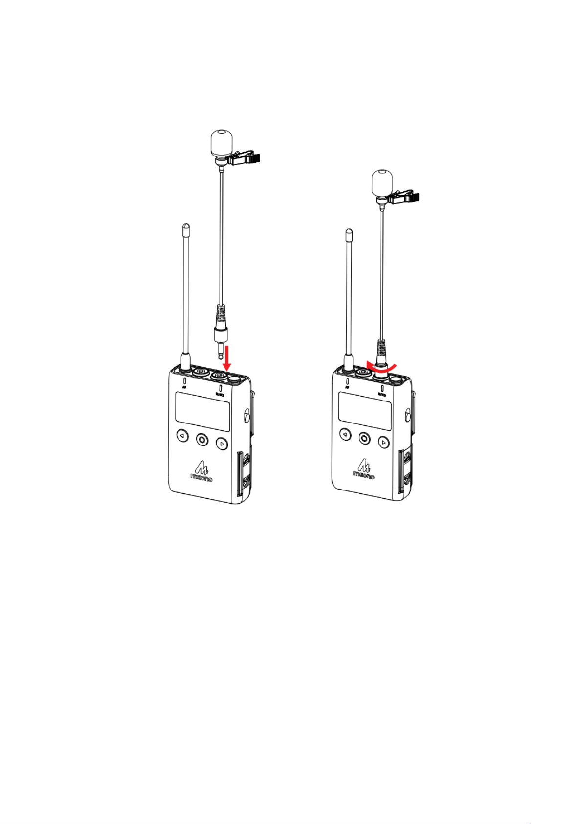
Mount the microphone to the transmitter
Insert the collar clip into the jack marked with “MIC” on the transmitter. To ensure a secure
connection, be sure to tighten it by rotating the ring.
Note
After turning off the transmitter, be sure to install or remove the microphone to prevent
damage to the plug during storage.
12
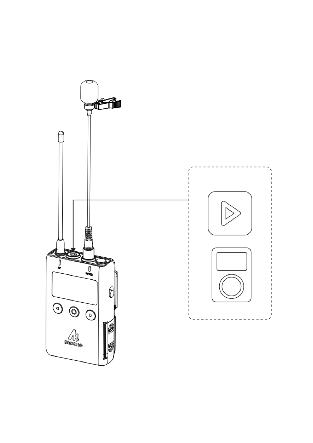
Line-in
The transmitter has the audio input interface “Line-in”, which can accept other audio
equipment to input to the transmitter and use this wireless microphone system for
transmission.
Sound source
13
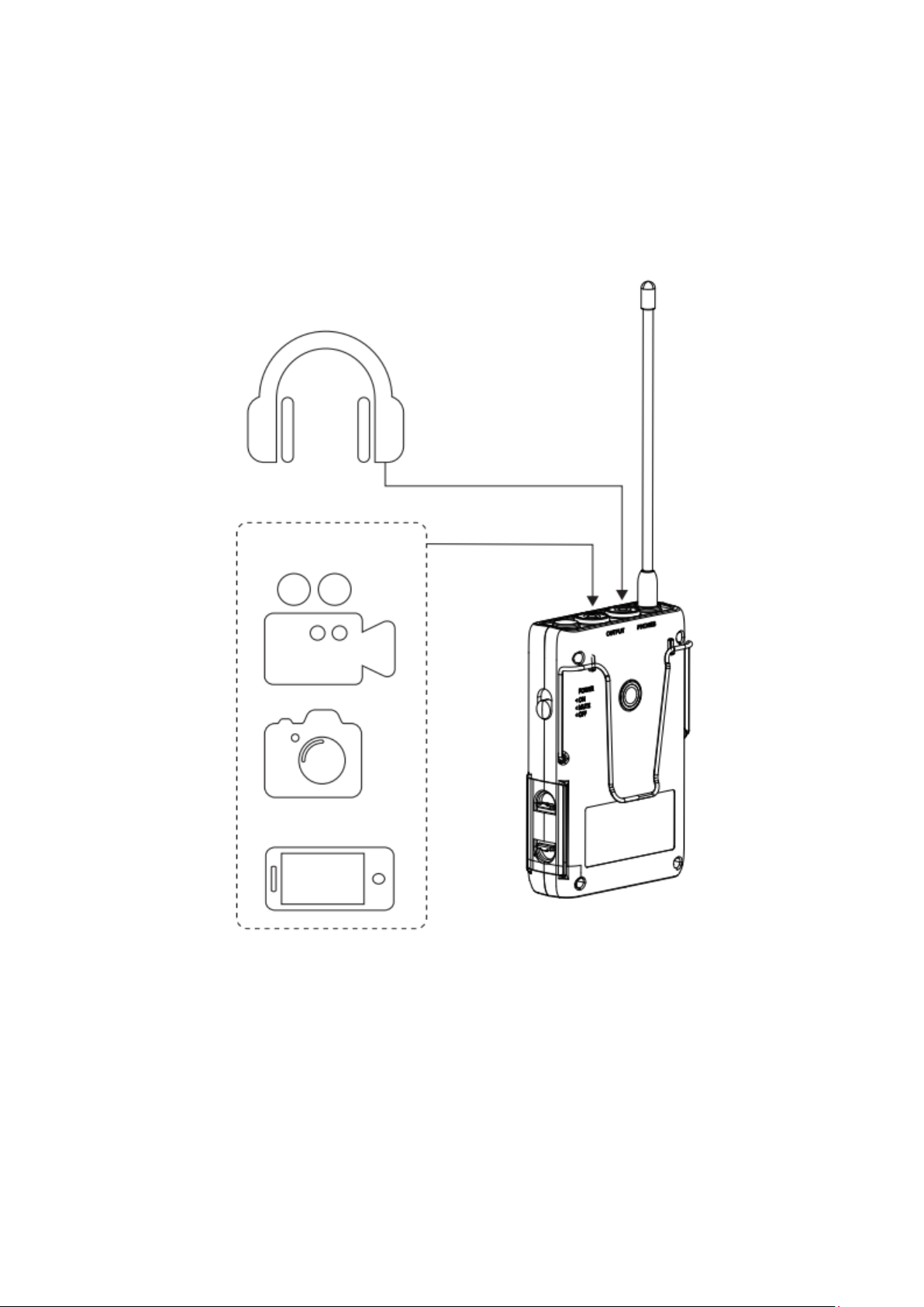
Connection to monitor headphones
•The receiver has a monitoring function to indicate when the headphones are
connected. Please insert the 3.5 mm connector of the headphones into the “PHONES”
jack of the receiver.
•“OUTPUT” interface is an audio output interface, used to connect various recording
devices or smartphones.
Note
Please turn down the receiver volume before the headphones is connected to protect your
hearing.
Headphone
Filming devices

14
Camera cold shoe mount installation
Follow the steps below to install the camera cold shoe mount:
•Align the screw of the cold shoe socket with the screw hole on the back of the
machine and screw it clockwise.
•Adjust the square part of the cold shoe mount accordingly.
•Tighten the compression block on the side of the cold shoe to prevent it from
loosening.

15
Belt clip installation
When using a belt clip, please remove the cold shoe mount first.
Installing the belt clip:
The belt clip of AU-WM730 can be easily removed and reinstalled on the belt pack
transmitter.
Follow the steps below to install the belt clip:
•Push the clip outwards to make one side of the clip pop out.
•Push the clip out of the other side to completely remove the clip from the transmitter.
•Align the belt clip with the hole in the transmitter, ensuring the clip faces the right
direction.
•Insert the other end of the clip into the belt transmitter.

16
Transmitter & receiver set-up
Turn on the device
Slide up the switch on the right side of the transmitter and receiver for about 2 seconds, the
screen displays information, and the boot is complete.
Switch the channel and pairing
Press the “function key”, when the “CH” flashes, adjust the “left / right button” to switch the
channel of the transmitter and receiver to the same value, and press the “function selection
key” again to confirm. If the transmitter is CH1, the receiver is also tuned to CH1.
Push the power switch
up
Channel value
17
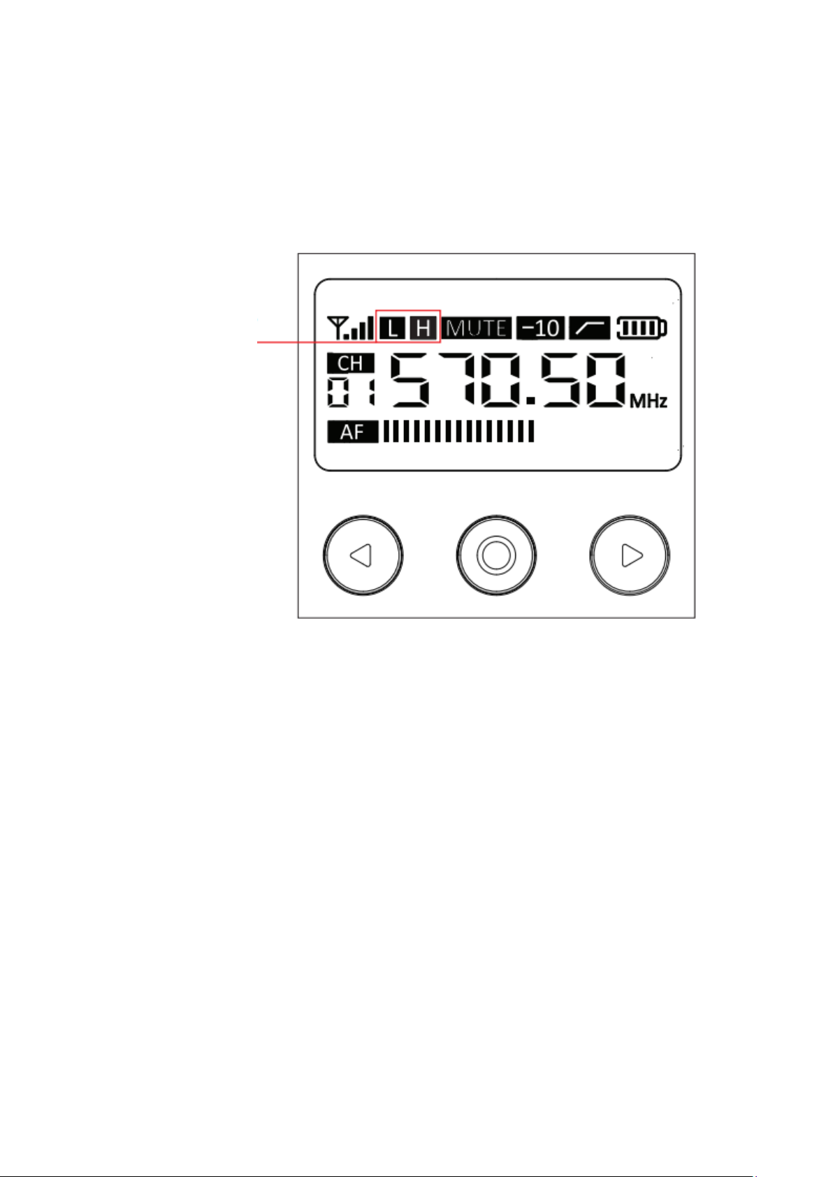
Transmit power set up: L/H
•The transmit power needs to be set on the transmitter. Constantly press the “function
key” until the screen display L or H symbol flashing
•Press the “Left / Right Button” to select high or low power.
•Press the “Function selection key” again to confirm and complete the power
adjustment.
Note
Select the high-power “H” mode, the working range will increase, but at the same time, it will
consume more power. Please pay attention to the battery status and replace it in time to
avoid power shortage. It is recommended to tun on low power “L” mode for use in
circumstances of small distance without obstacles, which is beneficial to prolong the battery
life.
Power mode display

18
Power Switch
•The switch of transmitter and receiver is a three-way switch, corresponding to power
off, mute and power-on.
•By turning the swich of the transmitter or receiver, the mute mode can be turned on
•Adjust the output volume on the receiver. Press the "Left / Right Button" to adjust the
output volume of the receiver. At the same time, the value of the "Volume" displayed
on the screen will vary between 0-15. The higher the value shows, the higher output
volume is.
Power On
Mute
Power Off
Output volume
19
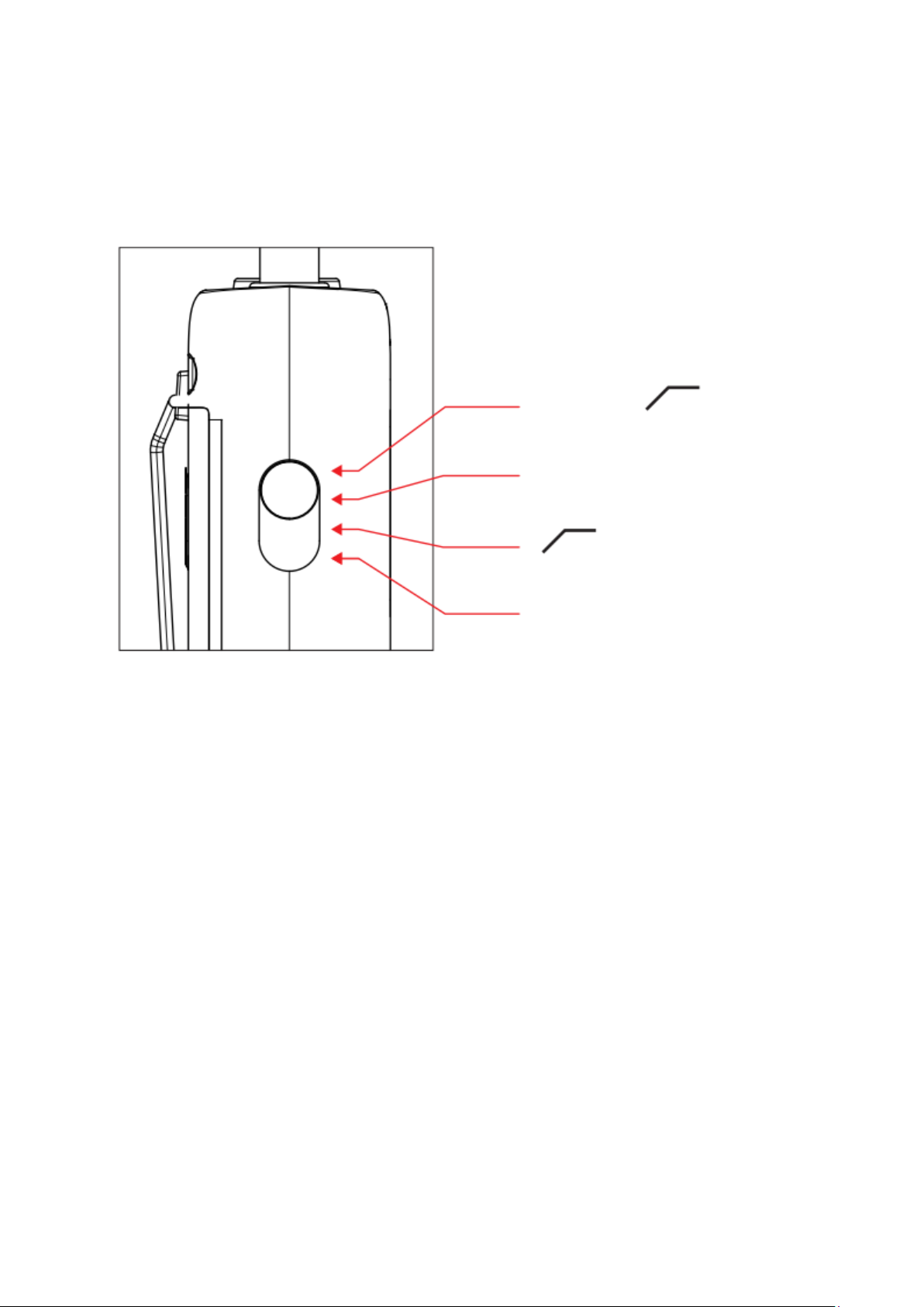
Low cut filter and attenuation function settings
This function can only be set on the transmitter.
The function switch on the left side of the transmitter can be adjusted in four levels,
corresponding to the normal, low cut, attenuation, attenuation + lowcut.
Use the switch on the left side of the transmitter to select these modes
-10 dB +
-10 dB (attenuation)
(Low cut)
NORMAL (normal)

20
Troubleshooting
If you encounter any problems when using the AU-WM730 wireless microphone system,
please follow the methods below to troubleshoot. If you still have issues, please contact us.
Status
Reason
Measure
Can’t turn on
the device
The polarity of the battery in the battery
compartment is incorrect.
Correct the polarity of the battery.
Battery died.
Replace with a new battery
The battery terminals in the transmitter are dirty.
Clean the +/- terminals.
The battery is
about to run
out
The battery has run out.
Replace with a new battery.
You are using alkaline batteries
Use alkaline batteries. We
recommend using alkaline
batteries for the best performance
Use AU-WM730 system under cold temperature
Power consumption is higher than
normal
Can’t change
the channel
Not in the channel setting mode
Press the function key to select the
channel, and then adjust it with the
“Left/Right Key”.
Has no sound
The channel of the transmitter and the receiver is
not matched
Set the transmitter and receiver to
the same channel
Volume is too
low
Set too low the volume of the receiver
Adjust the volume to transmit to
the highest level in the entire
signal path without distortion to
obtain the best signal-to-noise
ratio.
Is inserted to the signal input jack of the transmitter
by mistake
Remove the cable from LINE IN
and insert it into the microphone
jack
Distortion
The volume of the receiver is inappropriate
The volume of the receiver is
inappropriate
The channel of the transmitter and the receiver is
not matched
Set the transmitter and receiver to
the same channel
Use mono headphones
Use stereo headphones with 3.5
mm connector
Table of contents
Languages:
Other Maono Microphone manuals

Maono
Maono AU-AM200-S1 User manual

Maono
Maono AU-A04TC User manual

Maono
Maono AU-903 User manual

Maono
Maono AU-PM422 User manual

Maono
Maono AU-C03 User manual

Maono
Maono DGM20 User manual

Maono
Maono AU-AM200 S4 User manual

Maono
Maono DM20 User manual

Maono
Maono AU-PM320S User manual

Maono
Maono AU-WM800 User manual


