MAP-Tech MAP Pilot User manual


1
Contents
1INTRODUCTION .......................................................................................................................................6
1.1 WARNINGS -----------------------------------------------------------------6
1.2 CAUTION -----------------------------------------------------------------6
2THE MAP PILOT SYSTEM ..........................................................................................................................7
2.1 MAP PILOT SYSTEM COMPONENTS ------------------------------------------------7
2.1.1 MAP Pilot –P/N MP-PMA02A ...........................................................................................................7
2.1.2 MAP Pilot Data Harness –P/N MP-ECMA01S................................................................................... 8
2.1.3 MAP Pilot Power Harness –P/N MP-ECMA01P ................................................................................ 9
2.1.4 MAP Pilot GPS Antenna –P/N MP-ECMA01G................................................................................... 9
2.2 MAP MULTI-FUNCTION DISPLAY ------------------------------------------------ 10
2.2.1 MAP MFD –P/N MP-PDM01A ........................................................................................................ 10
2.2.2 MAP Interface Cable –P/N MP-ECPD01E ....................................................................................... 10
2.2.3 MAP MFD GPS Module –P/N MP-ECPD02G...................................................................................11
2.2.4 MAP MFD Power Cable –P/N MPECPD01P .................................................................................... 11
2.2.5 MAP MFD USB-to-Audio Cable –P/N MP-ECPD01X ....................................................................... 11
3MAP INSTALLATION PROCEDURE ..........................................................................................................12
3.1 VESSEL CONFIGURATION SCHEMATIC --------------------------------------------- 12
3.2 INSTALLING THE MAP PILOT ---------------------------------------------------- 12
3.3 INSTALLING THE MAP MFD ---------------------------------------------------- 13
3.4 GENERAL WIRING DIAGRAM ---------------------------------------------------- 14
4THE MAP APPLICATION...........................................................................................................................15
4.1 APPLICATION INSTALLATION NOTE ----------------------------------------------- 15
4.2 MAP APPLICATION CONFIGURATION---------------------------------------------- 15
4.2.1 Configuring your mobile device ...................................................................................................... 15
4.2.2 Connecting to the MAP Pilot ............................................................................................................16
4.3 WAYPOINT SETTINGS ---------------------------------------------------------- 17
4.3.1 Adding and deleting waypoints ...................................................................................................... 17
4.3.2 Changing waypoint coordinates ...................................................................................................... 18
4.3.3 Loading and running routes............................................................................................................ 19
4.3.4 Changing the next waypoint........................................................................................................... 19
4.3.5 Saving and loading waypoint files................................................................................................... 20
Saving a waypoint file................................................................................................................................................20
Importing a waypoint file ..........................................................................................................................................21
4.4 MODES OF OPERATION -------------------------------------------------------- 21
4.4.1 Changing the mode of operation ..................................................................................................... 21

2
4.5 REMOTE HELM OPERATION ---------------------------------------------------- 22
4.5.1 Changing to remote helm operation............................................................................................... 22
4.5.2 Trimming the remote helm .............................................................................................................22
4.6OTHER FEATURES ----------------------------------------------------------- 23
4.6.1 Scribbling a route ............................................................................................................................ 23
4.6.2 Adding a favorite point ................................................................................................................... 24
4.6.3 Displaying favorite points ............................................................................................................... 25
4.6.4 Deleting a favorite point ................................................................................................................. 26
5THE MAP PLANNER................................................................................................................................27
5.1 MAP PLANNER INSTALLATION ------------------------------------------------- 27
5.1.1 Configuring computer network settings ..........................................................................................27
5.1.2 Connecting to the MAP Planner...................................................................................................... 27
5.2 MANUAL REMOTE OPERATION-------------------------------------------------- 29
5.3 AUTO USV OPERATION ------------------------------------------------------- 30
5.3.1 Route Planning................................................................................................................................ 30
5.3.2 Engaging AUTO Mode..................................................................................................................... 32
Changing the starting waypoint ................................................................................................................................32
Notes.........................................................................................................................................................................33
APPENDIX A MAP PILOT SPECIFICATIONS .................................................................................................34
APPENDIX B MAP MFD SPECIFICATIONS...................................................................................................35

3
List of Figures
Fig. 1: The MAP Control Box (MAP Pilot)................................................................................................7
Fig. 2: MAP Pilot diagram........................................................................................................................7
Fig. 3: Connecting to the MAP Pilot through Wi-Fi.................................................................................7
Fig. 4: MAP data harness.........................................................................................................................8
Fig. 5: MAP Power Harness.....................................................................................................................9
Fig. 6: GPS antenna schematic................................................................................................................9
Fig. 7: The MAP Multi-Function Display................................................................................................10
Fig. 8: MAP MFD –back panel ..............................................................................................................10
Fig. 9: MAP Interface Cable...................................................................................................................10
Fig. 10: MAP MFD GPS module.............................................................................................................11
Fig. 11: MAP MFD power cable.............................................................................................................11
Fig. 12: MAP MFD USB-to-audio cable..................................................................................................11
Fig. 13: MAP Pilot configuration on a vessel.........................................................................................12
Fig. 14: The MAP Pilot installed on a flat surface .................................................................................12
Fig. 15: The direction of the MAP Pilot on the vessel...........................................................................12
Fig. 16: Dimensions of the MAP MFD ...................................................................................................13
Fig. 17: General wiring diagram of the MAP Pilot.................................................................................14
Fig. 18: Connecting to the MAP Pilot....................................................................................................16
Fig. 19: MAP application interface........................................................................................................16
Fig. 20: Powering on the MAP MFD......................................................................................................16
Fig. 21: MAP Application icon ...............................................................................................................16
Fig. 22: Trimming the remote helm ......................................................................................................22
Fig. 23: The MAP Planner icon on the Windows taskbar......................................................................27
Fig. 24: The Sail Plan window ...............................................................................................................28
Fig. 25: The Joystick window through the CTRL Setup window............................................................29
Fig. 26: Enable joystick control .............................................................................................................29
Fig. 27: MANUAL MODE joystick controls.............................................................................................29
Fig. 28: Sail Plan window.......................................................................................................................30
Fig. 29: View waypoint properties ........................................................................................................30
Fig. 30: Set waypoints ...........................................................................................................................31
Fig. 31: Delete a waypoint ....................................................................................................................31
Fig. 32: Upload the planned route........................................................................................................31

4
Fig. 33: Sail Data....................................................................................................................................32
Fig. 34: View waypoints ........................................................................................................................32
Fig. 35: Change the starting waypoint ..................................................................................................33
Fig. 36: Gradually steering towards the next waypoint (WP 2)............................................................33

5
List of Tables
Table 1: Status LED indicators.................................................................................................................7
Table 2: MAP data harness connector heads .........................................................................................8
Table 3: Wiring pinouts for the MAP data harness.................................................................................8
Table 4: MAP power harness connector heads ......................................................................................9
Table 5: Wiring pinouts for the MAP power harness .............................................................................9
Table 6: MAP Application buttons ........................................................................................................17
Table 7: MAP Planner control modes ...................................................................................................28
Table 8: Mode LED status .....................................................................................................................28
Table 9: Sail Plan buttons......................................................................................................................28
Table 10: Sail Data buttons...................................................................................................................32
Table 11: AUTO MODE line colors........................................................................................................33

6
1 Introduction
This manual has been created for users of the MAP Pilot by MAP Marine Technologies. It includes
detailed instructions for the installation of the autopilot and its accessories, as well as instructions on
how to connect to its accompanying mobile application for the autonomous navigation of your vessel.
Please ensure that you follow all warnings and safety instructions to safely install this system.
If you have any queries regarding the installation process, or if the appropriate configuration for your
vessel is not available in this document, please contact your MAP dealer. Visit us online at
www.almarakeb.net or contact MAP-Tech System support by phone at +971 6 538 5196.
Warnings
•Users are responsible for the safety of their vessels, and the passengers and crew onboard.
•Never leave the control station unattended and stay alert for navigational hazards; the MAP
Pilot system cannot avoid obstacles.
•Always start the boat in HOLD MODE.
•Always switch on the autopilot pump in AUTO MODE and switch off the pump in MANUAL
MODE.
•Never operate the system under the influence of drugs or alcohol.
•Always refer to the manual for operational information.
•The suppliers of the MAP Pilot System are not responsible for any accident that may occur
from use of this system or otherwise.
Caution
•The MAP Pilot has an accuracy of ±20 meters.
•You should learn to operate the MAP Pilot in hazard-free open water.
•Always cross check the latest naval charts for new construction projects.
•Always use safety goggles, gloves, and a dust mask while installing the MAP Pilot System.
•Use the mounting templates provided for MAP Pilot and MAP MFD to drill holes.
•Beware of fuel tanks, electrical cables, and hydraulic hoses while drilling holes.
•The Wi-Fi of the MAP Pilot has a range is 10 meters in perfect weather conditions.
7
2 The MAP Pilot System
MAP Pilot System Components
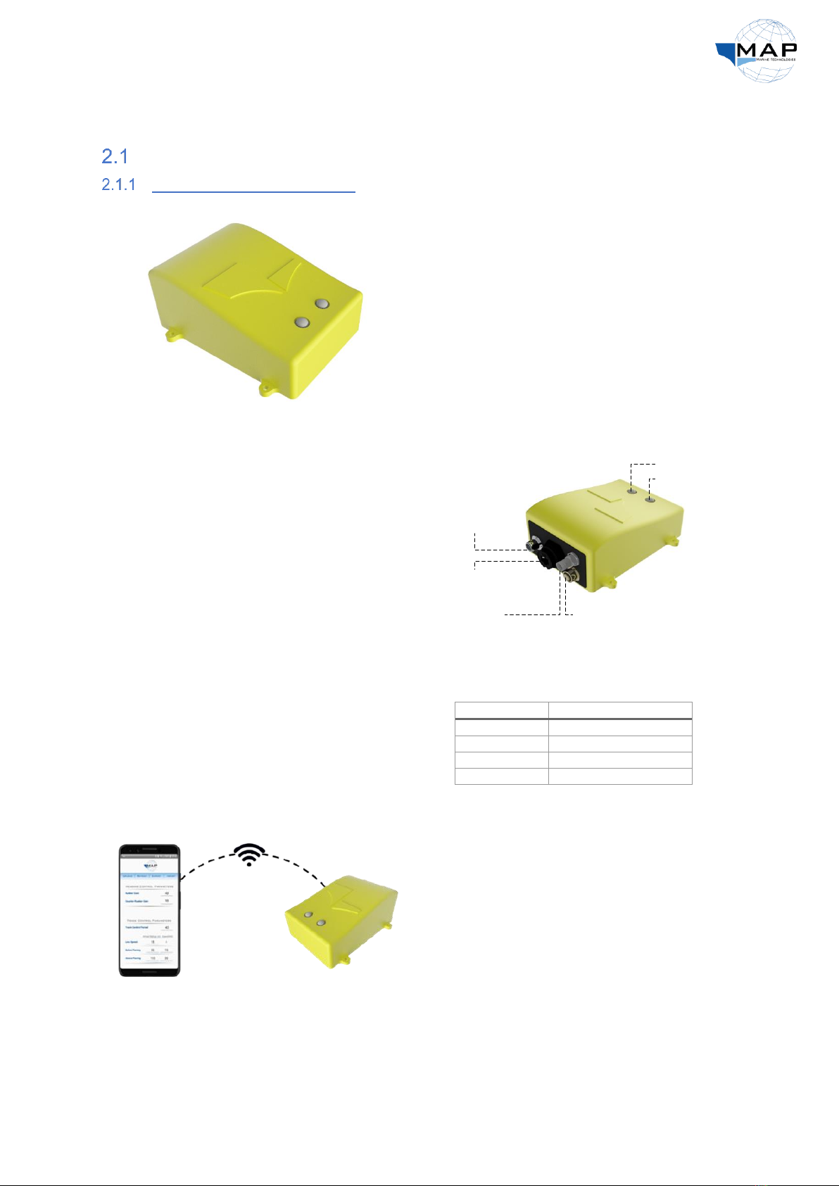
MAP Pilot –P/N MP-PMA02A
Fig. 1: The MAP Control Box (MAP Pilot)
The MAP Pilot acts as the brain of the autopilot
system. It is equipped with an INS, a solid-state
compass, and a GPS module to estimate the
heading and position of your vessel. The MAP
Pilot controls the steering pump based on the
desired route and sensory data of the vessel. It
connects to the control tablet or an Android
device via Wi-Fi.
The MAP Pilot has four external connectors for
its cable harnesses and the GPS antenna, and
two LED indicators, shown in Fig. 2. It also has
an Ethernet port, which can be used to connect
the MAP MFD. Refer to the sections that follow
for details on each component.
Fig. 2: MAP Pilot diagram
The MAP Pilot also consists of two LEDs. The
function of the status LED describes the status
of the MAP Pilot, as listed in Table 1. For
information on the mode LED, refer to Table 8
on page 28.
Table 1: Status LED indicators
Description
LED color
Autopilot initializing
Flashing yellow
No GPS fix
Flashing purple
Autopilot ready
Solid green
Autopilot malfunctioning
Solid red
Fig. 3: Connecting to the MAP Pilot through Wi-Fi
The MAP Pilot is accompanied by the MAP
Application, which allows you to connect to the
autopilot, configure it, and plan and upload
routes. The application is available on the MAP
MFD, as well as on the Google Play Store. You can
connect the MAP Pilot to your phone through Wi-
Fi, allowing you to access the application’s
interface, as shown in Fig. 3.
Power Harness
Data HarnessGPS Module
Ethernet Port
Status LED
Mode LED

8
MAP Pilot Data Harness –P/N MP-ECMA01S
The MAP Data Harness serves two functions on the MAP Pilot:
•It provides feedback from the rudder position sensor of your vessel.
•It allows you to configure the MAP Pilot through your device.
Fig. 4: MAP data harness
As shown in Fig. 4, the power cable
consists of 2 connector heads,
detailed in Table 2. For further
information on the wire pinouts of
the harness, refer to
Table 3.
Table 2: MAP data harness connector heads
Connector Label
Connector P/N
Contact P/N
MA2
M12
8-pin male
P3
Deutsch DTM04-4P
Deutsch 0460-202-20141
P4
Deutsch DTM06-4S
Deutsch 0462-201-20141
Table 3: Wiring pinouts for the MAP data harness
Cable Description
Connector A Label
Wire colors
Connector B Label
Pin B #
Setup
MA2
P3
1
2
3
4
Feedback
P4
1
3
4
9
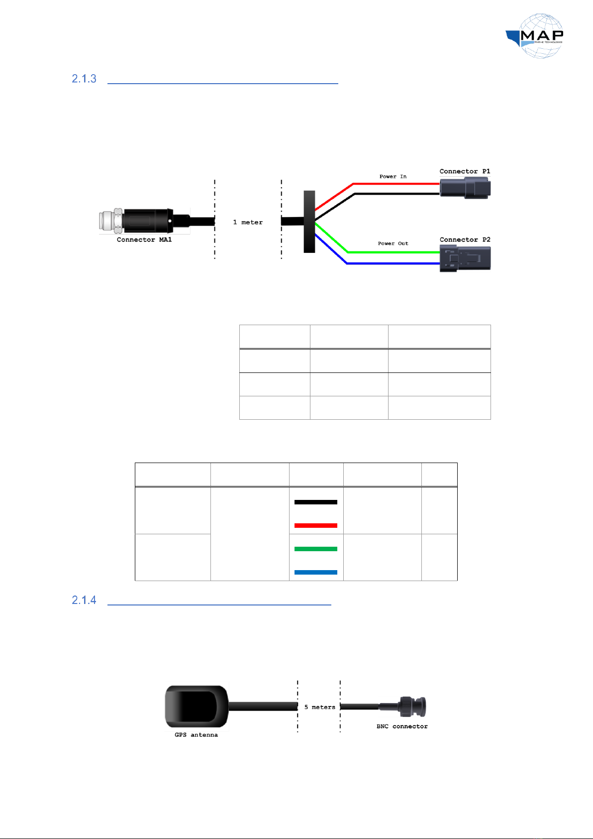
MAP Pilot Power Harness –P/N MP-ECMA01P
The MAP Power Harness serves two functions:
•It provides 12-VDC input power to the MAP Pilot, through the Power In connector.
•It provides power to the steering pump of your vessel, through the Power Out connector.
Fig. 5: MAP Power Harness
As shown in Fig. 5, the power
cable consists of 2 connector
heads, detailed in Table 4.
For further information on
the wire pinouts of the
harness, refer to Table 5.
Table 4: MAP power harness connector heads
Connector Label
Connector P/N
Contact P/N
MA1
M12
4-pin female
P1
Deutsch DTP04-2P
Deutsch 0460-204-12141
P2
Deutsch DTP06-2S
Deutsch 0462-203-12141
Table 5: Wiring pinouts for the MAP power harness
Cable Description
Connector A Label
Wire colors
Connector B Label
Pin B #
Power In
MA1
P1
1
2
Power Out
P2
1
2
MAP Pilot GPS Antenna –P/N MP-ECMA01G
The MAP GPS Antenna is a waterproof, weatherproof antenna that connects to the in-built GPS
module of the MAP Pilot unit. A female BNC connector is attached to the other end. For optimal
performance, it must be installed with a clear view of the sky.
Fig. 6: GPS antenna schematic

10
MAP Multi-Function Display
MAP MFD –P/N MP-PDM01A
Fig. 7: The MAP Multi-Function Display
The MAP Pilot may be accompanied by the MAP
Multi-Function Display (MFD), an LCD touchscreen
equipped with the Android OS. You can use it to
access the MAP Application (refer to Sec. 4 on page
15) in order to steer your boat, or to configure the
vessel for autonomous steering through a series of
waypoints set to your desired location.
The back panel of the MFD contains a set of connectors, as displayed in Fig. 8. These include the input
power connector, a connector for the GPS module used by the MAP Application, a USB-to-3.5mm
audio jack, as well as an auxiliary CAN bus port to interface with the marine sensors on your vessel:
Fig. 8: MAP MFD –back panel
The MAP MFD also has an Ethernet connection, which enables you to interface it with your MAP Pilot.
Details on the accessory cables of the MAP MFD are discussed in the sections that follow.
MAP Interface Cable –P/N MP-ECPD01E
The MAP Interface Cable connects the MAP Pilot to the MAP MFD. It uses the standard RJ45 Ethernet
port on the back of the MAP Pilot, and the M12 X-coding connector on the MAP MFD labeled
“Ethernet”. The cable is illustrated below:
Fig. 9: MAP Interface Cable
GPS Module
Input Power USB CAN Bus
Ethernet

11
MAP MFD GPS Module –P/N MP-ECPD02G
The MAP MFD is accompanied by the MAP MFD GPS Module, providing location data to the MFD for
the MAP Application, and to any other user-dictated software installed on the device. The GPS module,
illustrated below, is connected to the GPS connector of the MAP MFD (refer to Fig. 8 on page 10):
Fig. 10: MAP MFD GPS module
MAP MFD Power Cable –P/N MPECPD01P
The MAP MFD requires a power supply of 12V @ 4A, provided via the MAP MFD Power Cable,
illustrated below:
Fig. 11: MAP MFD power cable
MAP MFD USB-to-Audio Cable –P/N MP-ECPD01X
The MAP MFD has a free USB port built into the back panel, as illustrated in Fig. 8 on page 10. The port
can be used to play audio from the MAP MFD, using the MAP MFD USB-to-audio cable:
Fig. 12: MAP MFD USB-to-audio cable

12
3 MAP Installation Procedure
Vessel Configuration Schematic
Fig. 13 illustrates the arrangement of the MAP Pilot in relation to other components, such as the
autopilot pump and the GPS antenna.
Fig. 13: MAP Pilot configuration on a vessel
Installing the MAP Pilot
Before installing the MAP Pilot, it is important for you to completely understand the requirements for
installing the autopilot to maximize its accuracy. The mounting location for the autopilot should be:
•kept 1 meter away from any magnetic field.
•on a flat surface, as shown in Fig. 14:
Fig. 14: The MAP Pilot installed on a flat surface
•placed with the front of the MAP Pilot in the direction of the bow of the vessel, as shown in
Fig. 15:
Fig. 15: The direction of the MAP Pilot on the vessel
12V Power Supply
AP commands
GPS Antenna
GPS coordinates
User input
MAP MFD
MAP Pilot
AP Steering Pump
Feedback from rudder
GPS Antenna
GPS coordinates
13
•well-ventilated, to prevent the MAP Pilot from overheating (operating temperature >65◦C).
•easily accessible for the routing of power connections and cables.
•installed away from vibrations.
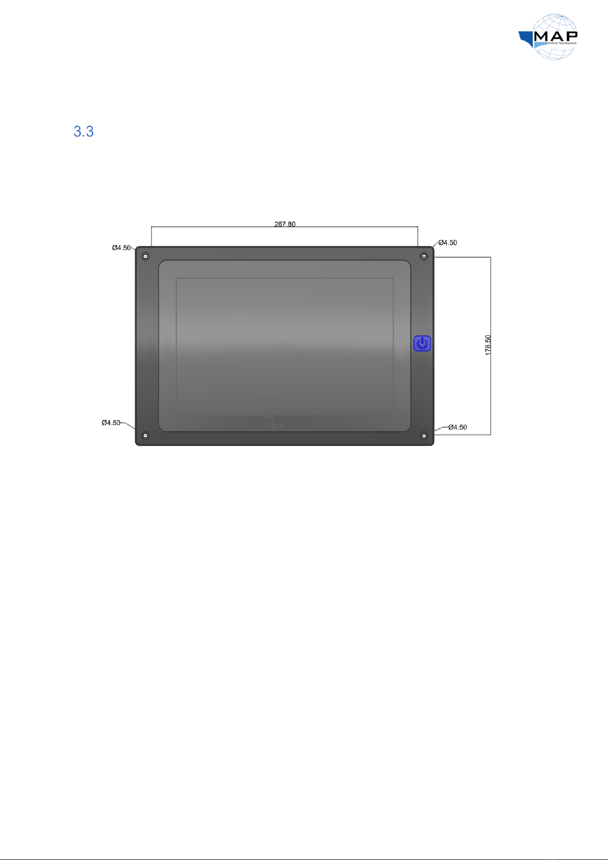
Installing the MAP MFD
The MAP MFD can be installed on the console of your USV, along with the control interfaces for other
equipment on your vessel. Please refer to Sec. 3.1 on page 12 to see an example of the location and
position of the MAP MFD. The dimensions of the MAP MFD are illustrated below:
Fig. 16: Dimensions of the MAP MFD
The mounting template of the MAP MFD is available in Appendix B.
14
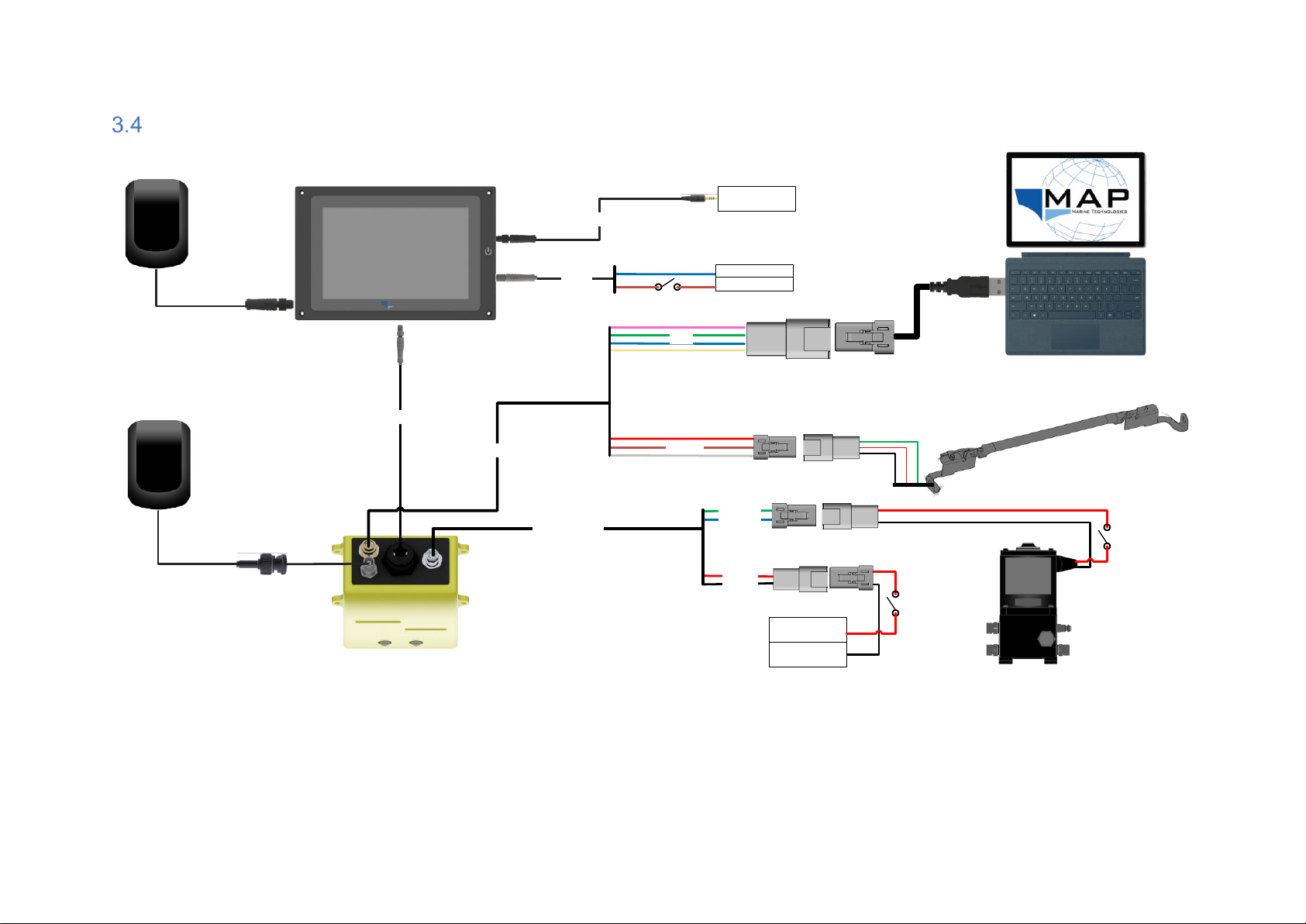
General Wiring Diagram
Fig. 17: General wiring diagram of the MAP Pilot
MAP Pilot
Setup
GPS Antenna
Feedback
Power Harness
Power Out
Power In
Autopilot Steering Pump
12V
GND
Rudder Position Sensor
Laptop
MAP MFD
MAP Interface Cable
Data Harness
GPS Antenna
Power GND
+12V
Input Power
Input Power
Audio Device
USB-to-Audio
Pump Switch
AP Switch
MFD Switch
15
4 The MAP Application
Application Installation Note
Check all the connections are made as per the wiring diagram in Sec. 3.4 on page 14. Install the MAP
Application on your Android device from www.almarakeb.net. Note that the MAP Application can
only connect to one device at a time.
MAP Application Configuration
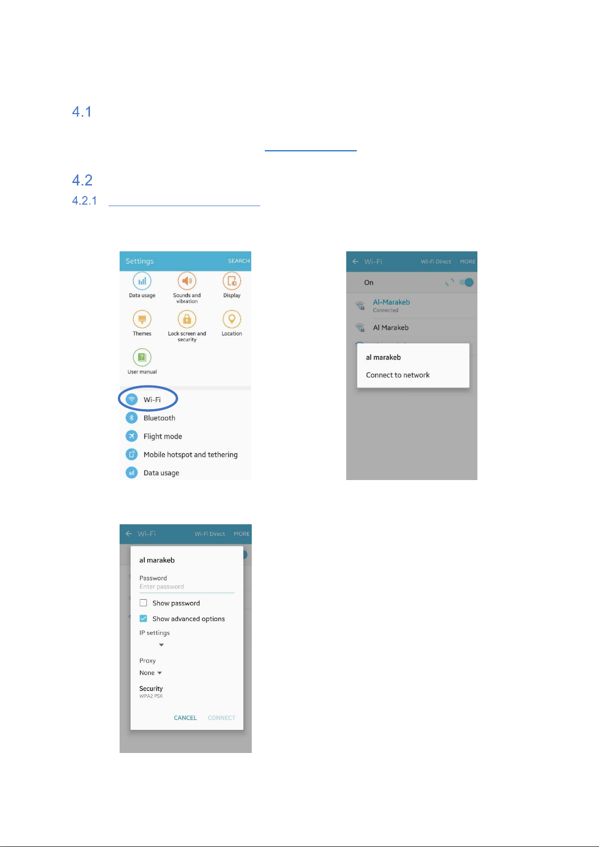
Configuring your mobile device
1. Enter the Wi-Fi settings of your mobile
device:
2. Find the Wi-Fi network of your MAP
Pilot. The SSID is printed on your unit:
3. Enter the password provided, printed on
your MAP Pilot:
Static
16
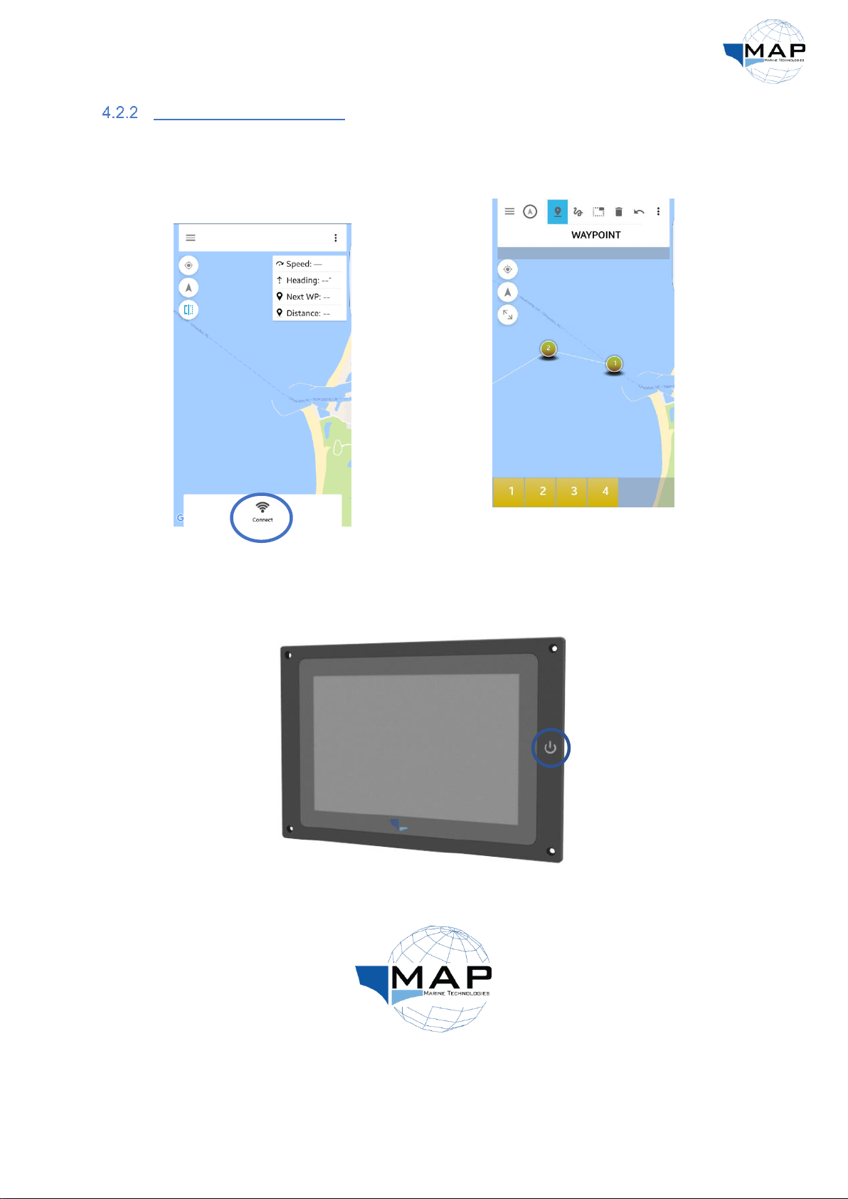
Connecting to theMAP Pilot
1. Connect to the MAP Pilot by clicking the
Connect button at the bottom of the
MAP Application interface, as shown in
Fig. 18:
Fig. 18: Connecting to the MAP Pilot
2. Observe the row of buttons on the top
of the screen shown in Fig. 19:
Fig. 19: MAP application interface
Note: You can connect to the MAP Application through the MAP MFD as well:
1. Power on the display:
Fig. 20: Powering on the MAP MFD
2. Select the MAP Application from the Desktop:
Fig. 21: MAP Application icon
17
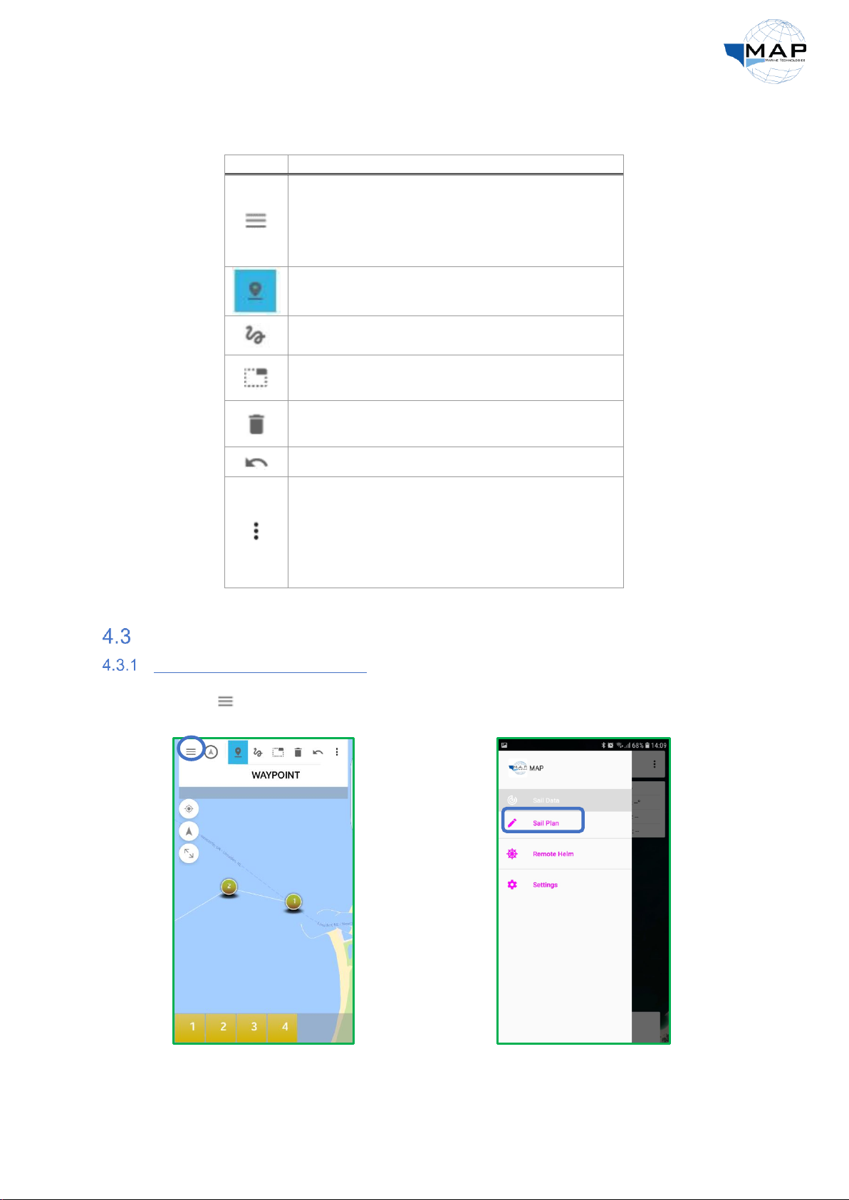
The functions of each button from Fig. 19 is described in Table 6 below:
Table 6: MAP Application buttons
Button
Description
Menu:
•
Sail Data
•
Sail plan
•
Remote Helm
•
Settings
Add waypoints manually by
clicking on the map
Draws route on the map
Selects the waypoint which you
want to delete
Deletewaypoints
Undo
Menu option
•
Disconnect
•
Upload route
•
Download route
•
Import from file
•
Export to file
Waypoint Settings
Adding and deleting waypoints
1. Click on . You will find the following
options: Sail Data,Sail Plan,Settings
2. Click on Sail Plan.

18
3. To add a waypoint, click and then
press anywhere on the map to add the
desired waypoint at the intended
location:
4. To delete a waypoint, click and then
select the desired waypoint from the
Waypoints Bar at the bottom of the
screen:
Changingwaypoint coordinates
1. Select the desired waypoint from the
waypoints bar. A pop-up with latitude
and longitude entries will appear.
The entries must follow the World Geodetic
System (WGS): degrees, minutes and seconds.
2. After you have entered the longitude
and latitude values for the desired
waypoint, select Set Coordinates:
19
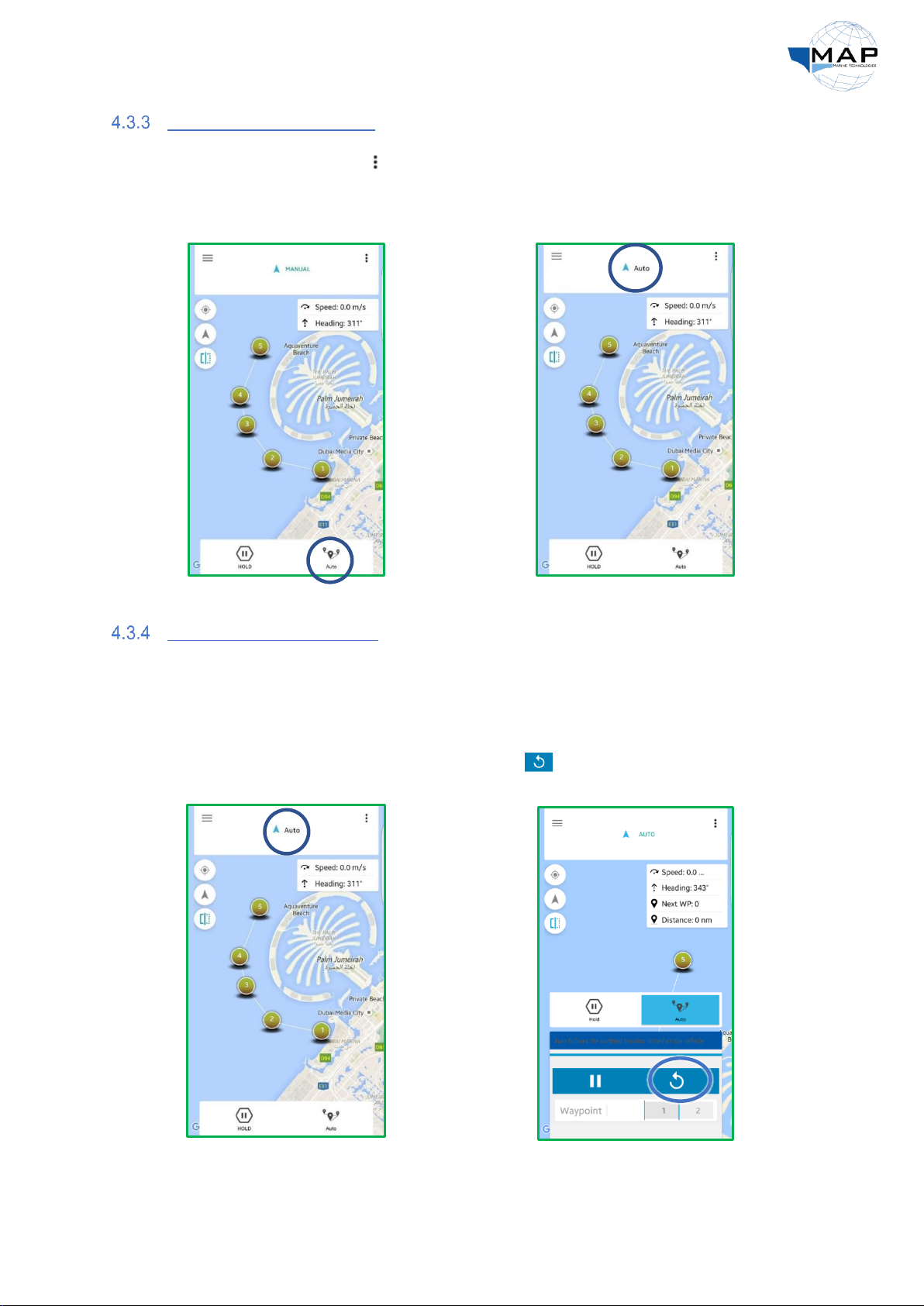
Loading and running routes
1. Click on the right-side menu and select
Upload Route. Once the route is
uploaded, go back to the Sail Data
screen and engage AUTO mode:
2. Note that the mode on the top of the
screen changes from MANUAL mode to
AUTO mode. Once in this mode, turn on
the pump switch.
Changing the next waypoint
The waypoint towards which the autopilot is headed can be modified using the Auto Control Panel.
For instance, if the autopilot was heading towards WP1, you can command the autopilot to
immediately go to WP3 using the Auto Control Panel.
1. In AUTO mode, press the AUTO button
at the top of the screen to engage the
Auto Control Panel:
2. To restart your route from WP1, press
from the Auto Control Panel:
Table of contents


