Muir STORM VR 600 User manual

T H E W O R L D P O W E R I N A N C H O R I N G S Y S T E M S
STORM
VR/ VRC/VFF 600
VERTICAL WINDLASS
VR/VRC/VFF 600 12/01/2015
muir.com.au
1

T H E W O R L D P O W E R I N A N C H O R I N G S Y S T E M S
Contents
Introdu tion page 3
Important Information
Safe Operation
Installation page 4
Installation Instructions
Quick Fit Reference Guide page 5
Depth of the Chain Locker page 6
andy ints page 7
Ele tri al Information page 7
Circuit breaker
Deck switches
Isolating switch
Batteries
Rotation
Wiring layout page 8
VR600 & VRC600 page 9
Operating Instructions and Servicing
Maintenance and Assembly Instructions page 10
VFF600 page 11
Operating Instructions and Servicing
Maintenance and Servicing page 12
Rope and Chain page 14
Rope Chain Management System (RCMS) Adjustment
Line Care
Rope/Chain Splice
Troubleshooting page 15
Water Prote tion Diagram page 15
Drawings
Exploded View of VR600 Storm
Exploded View of VR600 Storm with lo k pawl
Exploded View of VRC600 Storm
Exploded View of VFF600 Freefall
Solenoid Terminal Warning
Wiring Diagram
Maintenan e S hedule page 21
Warranty and Warranty Registration Card page 22
VR/VRC/VFF 600 12/01/2015
muir.com.au
2

T H E W O R L D P O W E R I N A N C H O R I N G S Y S T E M S
INTRODUCTION
Thank you for purchasing a Muir Storm Windlass. Muir go to great lengths to develop anchoring systems
that not only meet all of your performance and safety requirements, while also being designed with a
style and finish that enhances the aesthetics of your vessel. With Muir’s commitment to quality and use
of superior materials and processes we know you will be pleased with your investment. Rest assured
that through correct installation, operation and maintenance, your new Muir Windlass will give you
years of reliable performance.
IMPORTANT INFORMATION
To avoid damage to the geardrive, windlass or vessel when bringing the anchor up hard, it is a
preferred practice to mark the chain at approximately 5-meter intervals from the anchor, to alert the
operator to the anchor position. Alternatively an Auto Anchor can be used.
Under no circumstances should the windlass be operated if it is stalled or overloaded.
If anchor retrieval is impaired by high wind, heavy seas or if the anchor is snagged, ease the load by
either motoring or sailing slowly forward into the wind with a chain stopping device in place. The rope or
chain should be cleated off and the anchor driven out by the engine, otherwise the gearbox or shaft
can be damaged.
SAFE OPERATION
• Ensure that hands, feet, hair and clothing are kept clear of the windlass and other loose gear
when in operation.
• Ensure no one is swimming nearby as anchor is lowered or retrieved.
• Keep hands well clear of capstan, gypsy, chain and rope.
• The windlass should never be used for lifting people aloft.
• Do not use a windlass as a bollard for mooring, towing or being towed.
• When the windlass is in use or the anchor stowed, always ensure the clutch is tightened with the
clutch handle, and a Chainlock, Devil’s Claw or Snubber Line is fitted to retain the anchor. The
use of these accessories will prevent excessive loads on the geardrive or accidental release of
the anchor.
An optional feature on the VR600 is the gypsy locking pawl, which is used to lock the gypsy, by sliding
the locking pawl (located on the top of the chain cover) into the gypsy slots (located in the top flange
of the gypsy). This will prevent the release of chain when at anchor or when the anchor is stowed.
VR/VRC/VFF 600 12/01/2015
muir.com.au
3

T H E W O R L D P O W E R I N A N C H O R I N G S Y S T E M S
INSTALLATION INSTRUCTIONS
Figure (i)
Locate the windlass centrally fore and aft. Check that the chain leads
unhindered to the anchor roller. The chain runs onto the starboard side
of the gypsy, wraps around 180° and falls below deck through the
chain pipe. Ensure there is sufficient room around the windlass to allow
full rotation of the manual clutch handle (if supplied).
Figure (ii)
The centre height of the gypsy must be in the same plane as the chain
lead from the bow roller. If the deck is angled (fore & aft) or curved
(port to starboard) a suitably shaped mounting block will be required to
spread the load evenly over the deck surface and to mount the
windlass base on a level and even footing.
Figure (iii)
Place the shaped mounting block (if required) onto the deck. Using the
layout template supplied, mark the mounting centres and cut/drill the
holes.
Figure (iv)
Apply an appropriate sealant to the base plate and mounting block (if
required) and carefully tighten the nuts and washers onto the threaded
studs under the deck. Remove excess sealant.
For aluminium or steel hulled vessels, it is important to insulate the
windlass with a non-conductive gasket to avoid corrosion. This also
applies below deck for the mounting bolts, nuts and washers.
Where the deck construction is light or of foam sandwich construction,
a plywood stiffener of at least 16mm (5/8") thick should be fitted to the
underside of the deck to spread the load and to prevent the bolts from
pulling through the deck. Large diameter washers on the underside of
the stiffener assists to spread the load.
Figure (v)
1. Mount the windlass from above as shown.
2. From below, place washers and nut onto each stud and tighten.
Figure (vi)
5. Grease shaft, key, and gearbox hub, slide geardrive onto shaft
ensuring key is aligned. Rotate gearbox to prefered mounting position
and push further up into the base adaptor until retaining clip is locked
securely in the groove. (See installation diagram for Quick Fit Adaptor)
6. Apply Loctite 222 or equivalent and place washers and bolt in the
end of the shaft and tighten.
NOTE: During assembly, grease all moving parts and the deck plate grease nipple with a Lithium/Teflon
based grease. The motor/gear drive assembly should be protected with anti-corrosion film or grease
tape.
fig i
fig ii
fig iii
fig v
fig vi
fig iv
VR/VRC/VFF 600 12/01/2015
muir.com.au
4

T H E W O R L D P O W E R I N A N C H O R I N G S Y S T E M S
REFERENCE GUIDE
WINDLASS INSTALLATION using QUICK FIT ADAPTOR
1. Mount Windlass to the deck using supplied deck bolts
2. From underneath slide Motor/Gearbox assembly into the base
adapter making sure key and keyway are aligned, then push
until retaining clip locks securely in the groove
3. Apply Loctite or equivalent to the retaining bolt, then attach
washers and bolt to the end of the shaft and tighten
NOTE:
To make installation easier, ensure
the retaining clip is fitted to the
drive assembly before pushing onto
1
2
3
To disassemble:
Remove the bottom bolt and washers, pull out the retaining
clip and then slide down the Motor/Gearbox assembly.
Grease shaft & hub with
marine grade grease or other
appropriate anti-seize
compound
VR/VRC/VFF 600 12/01/2015
muir.com.au
5

T H E W O R L D P O W E R I N A N C H O R I N G S Y S T E M S
DEPTH OF THE CHAIN LOCKER
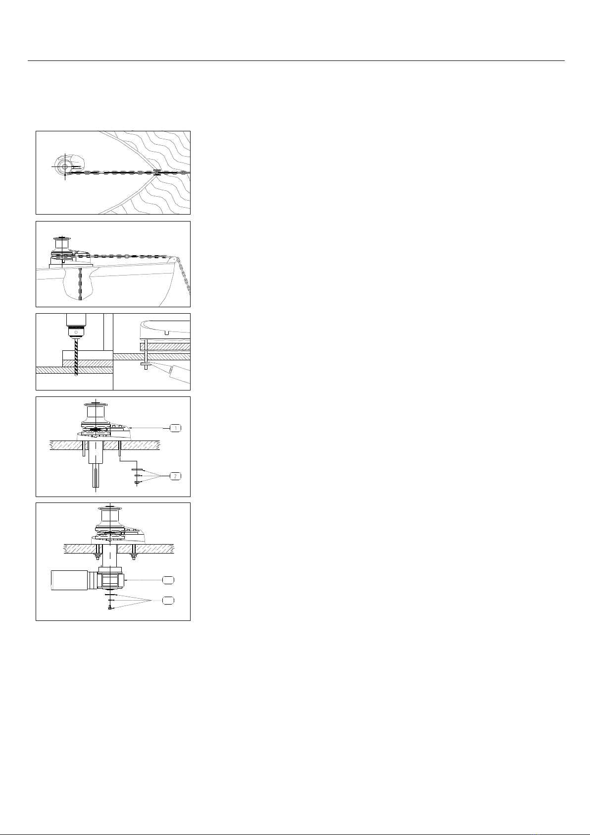
Ensuring that the vertical distance, (minimum fall), between the underside of the deck and the top of
the completely stored and heaped anchor rode in the locker will assist in determining the installation to
suit your vessel. Refer to the fall depth diagrams and the options detailed below. It is also
recommended that the chain be directed to the center of the chain locker. (See also water protection
diagram on page 15.)
If your vessel does not meet the minimum fall requirements for a vertical windlass, contact your Muir
retailer.
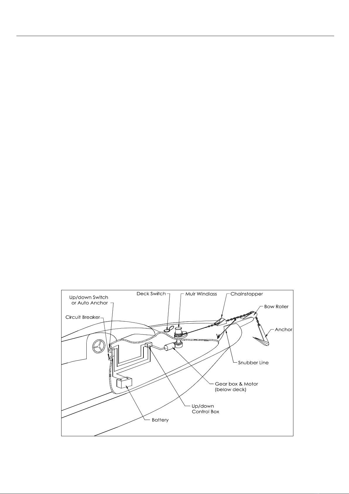
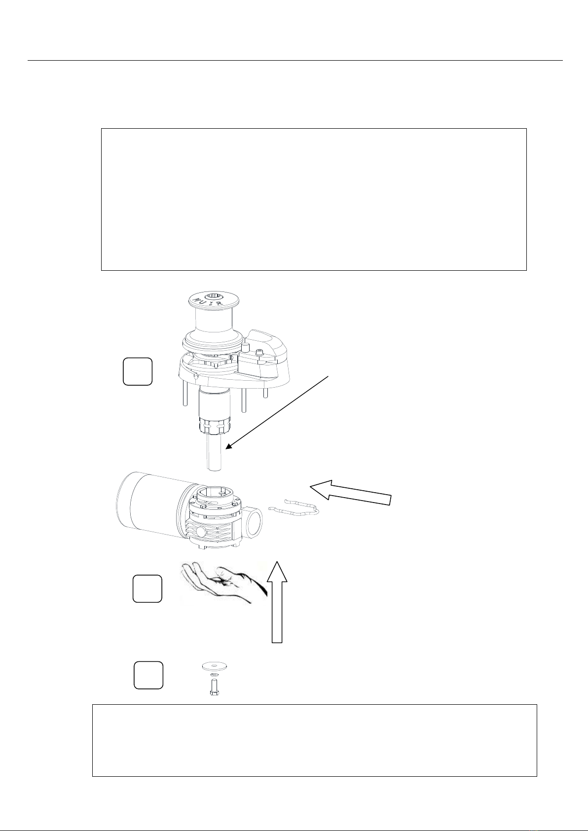
Verti al Windlass: The running gear, gypsy
and capstan are positioned above the
deck with the motor and gear drive
below. Vertical windlasses operate at
best with greater anchor rode fall than
the horizontal windlass and a minimum
fall of 300mm from top of stacked anchor
rode is recommended. This is particularly
important if using nylon line, which does
not fold and stack as well as chain.
Vertical windlasses minimise deck
intrusion and the modern curved lines of
the Muir windlass enhance the look of
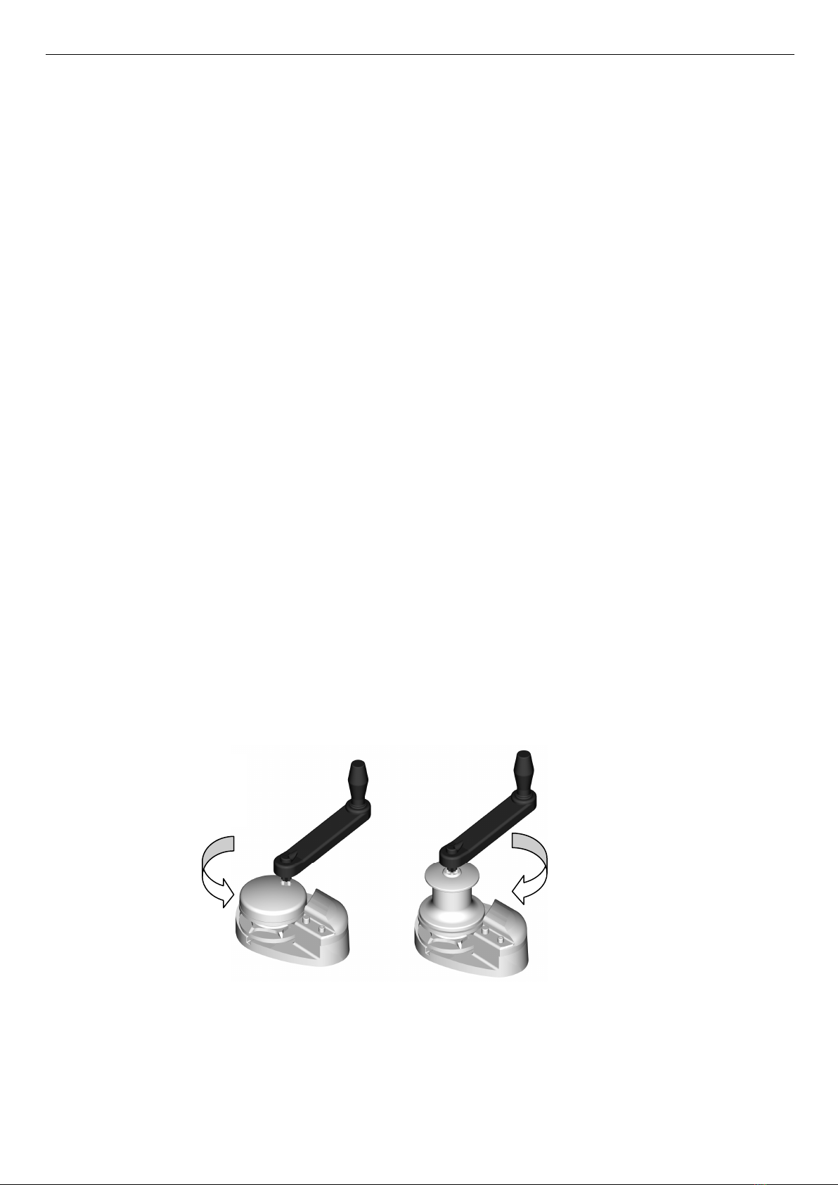
any vessel. A vertical windlass provides
the advantages of a I80-degree wrap of
the anchor rode around the gypsy.
Horizontal Windlass: Fully enclosed,
above deck, this style is usually preferred
where locker space is limited or
additional fall is required. The motor and
gear drive is fully enclosed in the housing
with nothing protruding below deck. The
horizontal windlass operates with
optimum anchor rode fall of at least
300mm from the top of the stacked
anchor rode, and due to the horizontal
orientation of the gypsy higher above
the deck there is additional fall provided.
These units are ideally suited for vessels
with less locker space.
Verti al Windlass
Model
Horizontal Windlass
Model
Minimum Fall
(Dist. Top of
Pile)
VR/VRC/VFF 600 R600 - 700 300 mm
VR/C 850 – 1250 & 2200 R1200 450 mm
VR/C 2500 – 3500 R2500 - 3500 650 mm
VR/C 4000 R4000 - 4200 800 mm
MINIMUM FALL
MINIMUM FALL
VR/VRC/VFF 600 12/01/2015
muir.com.au
6

T H E W O R L D P O W E R I N A N C H O R I N G S Y S T E M S
HANDY HINTS
It is a common error to locate the windlass too far forward, or too close to the bulkhead, where there
is insufficient room for chain and anchor stowage. The chain fall should be positioned in the centre of
the chain locker to maximise the fall of the chain. If the chain falls alongside a bulkhead or onto the
stem it will pyramid and be more likely to jam.
If the windlass requires positioning such that chain falls into an undesirable position, a metal tube can
be fitted under the hawser to redirect the chain to a more suitable position. This pipe should be at
least 2 times the diameter of the chain. It should also be as vertical as possible. Position the windlass in
the best location with the chain hawser facing forward.
Ensure sufficient room to run electric cables to the windlass. Follow the installation instructions,
including underdeck stiffening, deck camber, alignment, mounting blocks and sealing procedures.
The gearbox and motor can be located in one of 8 positions.
ELECTRICAL
See Wiring Diagrams for wiring instructions.
Cir uit breaker
(must be fitted to ensure warranty)
If the windlass is overloaded or stalled the circuit breaker will automatically cut power to the windlass
and protect the wiring and motor. The circuit breaker should not be used as an isolating switch, purely
for safety reasons.
De k Swit hes
are best located out to either port or starboard or directly behind the windlass in a
position where it can be easily reached with your foot or knee, preferably where you can view the
anchor and chain coming aboard.
Isolating Swit h
should be fitted in an accessible position for safety, ideally close to the battery or
switches. The isolating switch is not a circuit breaker.
Batteries
are best located as close to the windlass as possible. Larger cables will reduce the voltage
drop to the motor and the heat generated when running the windlass. Small diameter cables drop
voltage considerably. Use the following table as a guide to your required wire size:
Distance from battery to
motor (m)
Cable Size
(mm
2
) AWG Cable Diameter (mm)
7 (23’) 25 4 8 (5/16”)
9 – 17 (30’ – 55’) 70 1/0 12 – 15 (7/16” – 19/32”)
Rotation
: Windlasses may be wired for single or dual direction, using single or dual deck switches for
raising or lowering. Alternatively a remote control solenoid package with Toggle Switch, and
Pendant or Auto Anchor is available. Contact your Muir Retailer for further details
Solenoid Installation
We recommend that the solenoid is installed in an upright
position, where it has minimal exposure to sea water and
is in close proximity to the electric motor of the windlass.
For wiring information, please refer to the included wiring
diagram.
VR/VRC/VFF 600 12/01/2015
muir.com.au
7

T H E W O R L D P O W E R I N A N C H O R I N G S Y S T E M S
WIRING LAYOUT
TOL
NOT TO BE USED AS WIRING DIAGRAMS
5
4
6
1.
2.
3.
4.
5.
6.
BATTERY
CIRCUIT BREAKER
SOLENOID/CONTROL BOX
DECK SWITC ES
AUTO ANC OR
AUTO ANC OR SENSOR
AUTO ANC OR LAYOUT
1
2
4
BATTERY
CIRCUIT BREAKER
SOLENOID/CONTROL BOX
REMOTE SWITC
1.
2.
3.
4.
REMOTE SWITC LAYOUT
REMOTE / DECK SWITC LAYOUT
3
2
31
4
5
2
1.
2.
3.
4.
5.
BATTERY
CIRCUIT BREAKER
SOLENOID/CONTROL BOX
DECK SWITC ES
REMOTE SWITC
1
3
VR/VRC/VFF 600 12/01/2015
muir.com.au
8

T H E W O R L D P O W E R I N A N C H O R I N G S Y S T E M S
OPERATING INSTRUCTIONS – VR600 and VRC600
Manually releasing hain: To release the anchor rode, place the clutch handle into the clutch drive
Bi-square as shown in the diagram at the bottom of the page and turn anti- lo kwise to release the
clutch brake. Let the anchor fall and control the run of the chain by tightening the clutch handle
lo kwise using the clutch mechanism as a brake.
An horing: When laying at anchor use a chain stopper, nylon/chain bridle or snubber line to prevent
snatching and direct loading on the windlass main shaft. Never use the windlass as a mooring
bollard.
Retrieving hain: Before operating the windlass tighten the clutch with the clutch handle in a
lo kwise direction, then remove the clutch handle. If the anchor is buried hard, motor forward to
pull it free after hardening up on the windlass. This will ease the load on the windlass.
Rope hauling on the apstan: The capstan can be operated independently of the gypsy. Secure the
anchor rode, (with a chainlock, gypsy lock or snubber), then release the clutch. The capstan may
then be operated using the windlass motor.
Ele tri operation: Releasing and retrieving the anchor rode is identical when operating an electric
windlass. Always keep well clear of the windlass when releasing or retrieving chain and anchor. Keep
fingers, hair and clothing well clear when the windlass is in operation.
Auto An hor Laun hing: If the anchor roller can be positioned so that the anchor falls as soon as the
windlass is reversed, the whole operation can then be carried out remotely. Remote switching
controls are self centering and stop the windlass when the switch is released. Mark the anchor end of
the chain at 2 and 5 metre (6.5’ & 16.5’) intervals to enable the operator to judge when the anchor is
almost up. Go slowly for the last few metres of retrieval by letting go of the switch, rather than waiting
for the anchor to fly up over the roller and bang tight, as this practice puts excessive load onto the
bow roller, windlass and foredeck, so should be avoided.
SERVICING
Rinsing all deck gear with fresh water after every excursion ensures that salt deposits and corrosion
are kept to a minimum. We recommend that windlasses affixed to pleasure craft are stripped yearly
and all moving parts cleaned and greased with a grease suitable for marine applications, (such as
Duckhams Keenol or Castrol LMX). In the case of workboats and charter vessels we suggest that this
maintenance is carried out more frequently. Do not use soap based grease.
The geardrive is filled and sealed at factory with long life synthetic oil that does not require
replacement for the life of the geardrive.
Gradually loosen
to release the line
manually
Tighten to brake the
outgoing line
Fully tighten to retrieve
the anchor under power
VR/VRC/VFF 600 12/01/2015
muir.com.au
9

T H E W O R L D P O W E R I N A N C H O R I N G S Y S T E M S
MAINTENANCE AND ASSEMBLY INSTRUCTIONS – VR600 and VRC600
• The Motor/geardrive assembly should be protected with anti-corrosion film or grease tape.
• Check for any corrosion or paint chips and treat.
• Check motor terminals and clean.
Standard VRC600
For this you require the clutch handle, 3mm and 6mm
allen keys and a marine grade grease.
1. Remove two screws and chain cover.
2. Remove peeler.
3. Fully unscrew clutch nut and remove capstan.
Remove key from shaft. old the peeler arm out and
remove gypsy.
4. Repeat steps 1-3 in reverse order. Lubricate shaft,
gypsy, drive cone and capstan.
Standard VR600
For this you require the clutch handle, 3mm and 6mm
allen keys and a marine grade grease.
1. Remove two screws and chain cover.
2. Remove peeler.
3. Fully unscrew clutch nut and remove D washer. old
the peeler arm out and remove gypsy.
4. Repeat steps 1-3 in reverse order. Lubricate shaft,
gypsy and drive cone.
VR600 With Lo king Pawl
For this you require the clutch handle, 3mm and 6mm
allen keys, a small screwdriver and a marine grade
grease.
1. Remove screw on side of chain cover. Carefully
remove locking pawl, spring and ball bearing.
(Spring and ball bearing may be stuck to the bottom
of the locking pawl).
2. Remove two screws and chain cover.
3. Remove peeler.
4. Fully unscrew clutch nut and remove D washer. old
the peeler arm out and remove gypsy.
5. Repeat steps 1-4 in reverse order. Lubricate shaft,
gypsy and drive cone.
VR/VRC/VFF 600 12/01/2015
muir.com.au
10

T H E W O R L D P O W E R I N A N C H O R I N G S Y S T E M S
OPERATING INSTRUCTIONS: VFF600
The concept of the freefall windlass is to deploy and freefall an anchor remotely from the helm station.
1. Engaging the down switch or reversing the windlass automatically releases the clutch allowing the
chain gypsy to free wheel thus dropping the anchor.
2. Engaging the up switch of the windlass will automatically tighten the clutch allowing the winch to
take up any slack in the anchor rode. This must be done only when the an hor and all of the rode
has tou hed the bottom and not whilst in freefall.
3. Release the switch when sufficient slack in the anchor rode has been taken up.
4. To retrieve the anchor, operate the windlass in the up direction. It is also recommended that the
vessel is motored into the wind/towards the anchor to minimise excessive load on the windlass.
5. If necessary the windlass can be powered down without freefall. This is done by releasing the grub
screw and rotating the striker pawl 180 degrees. (See Maintenance and Servicing 3a, Page 1 ).
6. The clutch can also be operated manually using the above method. The clutch has a left hand
thread, so to release the clutch turn the handle in a clockwise direction and to tighten turn the
handle in an anti lo kwise dire tion.
7. For the efficient operation of the windlass periodically apply grease to the striker pawl located on
top of the chain pipe cover.
8. The Rope Chain Management System nylon fingerapplies pressure to the line and splice and must
be tightly tensioned onto the gypsy without line fitted by releasing the grub screw and adjusting
the finger pin by tightening anticlockwise.
IMPORTANT:
IT IS NECESSARY TO INSTALL AN ISOLATION SWITCH AS WELL AS A CIRCUIT BREAKER TO THE FREEFALL
WINDLASSES TO ISOLATE THE WINDLASS WHEN NOT IN USE. This is to prevent the rope and hain from
paying out if the win h is a identally reversed.
VR/VRC/VFF 600 12/01/2015
muir.com.au
11

T H E W O R L D P O W E R I N A N C H O R I N G S Y S T E M S
A
B
D
E
C
MAINTENANCE AND SERVICING
VFF 600 Free Fall Windlass
1. Tools required
(i) Muir clutch handle (P/N. F90-
ANNYL0600)
(ii) Phillips ead screw driver
(iii) Flat blade screw driver
(iv) 6mm (1/4") Allen key
(v) 3mm (1/8") Allen key
(vi) 3/16" Pin punch
(vii) VFF 600 exploded view Dwg. K08-
FREVFF0600
2. Removing lut h nut retaining washer (P/N.
P21-304020.0007.005) & screw (P/N. S33-
30406.00012). Place Flat blade screwdriver (A)
into slot screw and then turn anti-clock wise to
remove.
3a. Removing de lut hing pawl (P/N. P13-
PWL303VFF600A). Place 3mm (1/8" ) Allen key
(B) into grub screw and then turn anti-clock
wise to release.
3b. Removing 3/16" roll pin (S93-PIN04.76025).
Place 4mm (3/16") pin punch into point (C)
and then tap carefully with a hammer to
remove.
4. Removing hain over (P/N. P05-
CCV3160600FF). Place 6mm (1/4") Allen key
into (D) & (E) socket head cap screw (P/N.
S45-30406.35025) and then turn anti-clock wise
to remove. Now the chain cover can be
removed.
VR/VRC/VFF 600 12/01/2015
muir.com.au
12

T H E W O R L D P O W E R I N A N C H O R I N G S Y S T E M S
F
G
I
J
K
5. Removing PVC finger (P/N. R40-FGR3160600A).
Place 3mm (1/8") allen key into (F) grub screw
(P/N. S35-30406.35BSW006) and then turn anti-
clock wise to remove. The finger can now be
removed.
Re-assembly: Tensioning the finger: Place flat
bladed screwdriver into (I) slot of Pin, then turn
anti-clock wise ¼ turn & hold. Then tighten (F)
Grub screw.
6. Removing lut h ap (P/N. P07-
CLNBRZVFF600A1). Place Muir clutch handle
into bi-square (G) and then turn lo kwise
(left hand thread) to remove.
7. Removing gypsy (P/N. P10-A0600), peeler (P/N.
P05-PLR3160600) & stripper (P/N. P19-
STR3040600A). These parts can now be slid off
the main shaft ( ).
Re-assembly: When placing gypsy back on
the shaft make sure that the notches are on
top.
• Before re-assembly, grease the exposed
main shaft/cone (J) & gypsy bore (K).
• The Motor/geardrive assembly should be
protected with anti-corrosion film or grease
tape.
VR/VRC/VFF 600 12/01/2015
muir.com.au
13

T H E W O R L D P O W E R I N A N C H O R I N G S Y S T E M S
ROPE CHAIN MANAGEMENT SYSTEM (RCMS) ADJUSTMENT
Firm tension of the finger is required to reduce rope (nylon line) slipping through gypsy. To adjust this
tension (if line slippage is experienced) refer to the procedure below:
PROCEDURE:
Tools Required: Allen keys and a large flat
screwdriver.
1. Undo the two socket head screws with an allen
key to remove the chain cover.
2. Loosen the grub screw on the side of base with
an allen key for finger adjustment.
3. Turn screwdriver anti- lo kwise to tension the
spring. While holding the tension, re-tighten grub
screw.
4. Reattach the chain cover to finish the
adjustment.
Line Care
Using the wrong type of line may cause the line to jam or slip, causing excessive line wear. Muir
Windlasses are designed to run on 3-strand nylon line (supplied by Muir) which has been specially treated
with fabric softener to prevent it from hardening. It is recommended to soak your rope in fresh water
containing fabric softener every 3 months.
In case of a rope jam, slacken off the windlass clutch to free the jammed line. When retrieving the anchor
rode do not continue to run the windlass if the anchor or chain is jammed, as line slippage in the gypsy will
cause damage to the line.
Rope/Chain Spli e.
1. To stop rope unravelling, seize rope 400mm(16") from end
with whipping twine. Unlay strands.
2. After placing 20mm (3/4") of heat shrink sleeve tubing
through the last link of chain, pass one strand of rope
through sleeve and chain from one side and the other two
strands of rope from the opposite side. (See illustration).
3. While pulling all three strands tight, shrink the sleeve tightly
onto the rope using a hairdryer or fan heater or by
immersing in boiling water.
4. Remove seizing and complete back splice in normal manner
for two full tucks. With a hot knife pare down the three
strands by 1/3 and insert two further tucks. Pare down by
another 1/3 and finish with two tucks. Cut any remaining
tails.
VR/VRC/VFF 600 12/01/2015
muir.com.au
14

T H E W O R L D P O W E R I N A N C H O R I N G S Y S T E M S
TROUBLESHOOTING
ELECTRICAL
1. Check the battery circuit breaker and ensure the isolating switch is on.
2. Check battery is charged up to 12 or 24 volts (as relevant).
3. Check that the foot switch plunger is contacting.
4. Check remote control solenoid is contacting. If this is clicking, the problem may be low voltage, a
faulty solenoid or a wire not properly connected.
5. Check wiring between controls, solenoid and motor are intact.
6. If the motor will not turn after checking the above points, check that the motor bushes are not
worn or sticking.
MECHANICAL
1. Check that the clutch above the chain gypsy is tightened to the chain gypsy drive using the
manual handle supplied (refer to operating instructions section of this manual).
2. If the line slips check the tension on the finger and increase spring tension (refer to RCMS
adjustment section of this manual).
3. Check the drive key on main shaft to gearbox output.
4. Check the drive key between the gearbox and motor input.
WATER PROTECTION DIAGRAM
NOTE:
It is important to thoroughly lubricate all
mating surfaces with grease suitable for
marine applications.
Corrosion protection should be applied to
the external surfaces of the motor,
gearbox and adaptor and also in any
areas that water may lie.
Recommended products for anti
corrosion protection are Techtyl under
body anti corrosion film and Denso grease
tape.
If it is necessary to install the motor
below the chain access hole then a
chain pipe extension is required.
Wires and motor
clamp to bottom
where possible
Chain Pipe Extension
VR/VRC/VFF 600 12/01/2015
muir.com.au
15

16

17

18


This manual suits for next models
2
Table of contents
Other Muir Marine Equipment manuals
Popular Marine Equipment manuals by other brands

ALBIN PUMP
ALBIN PUMP Marine Defroster 9 kW Instructions for use

EMBRON
EMBRON Hatteland Technology HD 15T22 MMD F Series user manual

Em-Trak
Em-Trak I100 quick start guide

ZF Marine
ZF Marine ZF 285 Series manual

MaxPower
MaxPower VIP 150 Electric Installation operation & maintenance

Edgetech
Edgetech 701 DIGITAL LINK USER HARDWARE MANUAL

vesper marine
vesper marine WatchMate 850 Getting started guide

Stahl
Stahl YA6S Series operating instructions

Teknim
Teknim TFS-1181R installation manual

Kongsberg
Kongsberg Simrad EK80 installation manual

Garmin
Garmin GMI 10 Digital Marine Instrument Display installation instructions

Lofrans
Lofrans PROJECT 2000 USA instruction manual