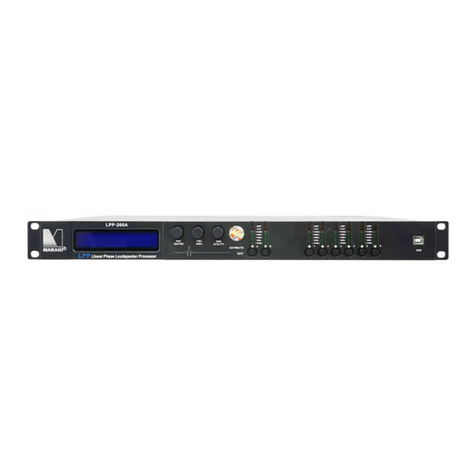
Marani LPP240A Instruction manual

LPP240A Quick User's Guide
Before to install the setup.exe, please make sure that the Net Framework 4.0 is already installed on
the PC used.
After install the setup.exe and run the app “LPP240A then the system show the following window
and after few seconds the main window
Below is introduction for the “Device List :

: Connect all device
: Disconnect all device
: Add device to the List
: Remove one or more device from the List
: Search Device
: Device Name
: Connection status of the device, by double clicking this characters, user can switch between
“On-line and “Off-line mode.
Click the icon, you will see below conversation window. Click the preferable connection mode and
device model. (In this case, device model shall be “LPP240A )
Note: When you connect under TCP/IP mode, please input the IP address of the device; if under
RS485 mode, please input the ID of the device as well.
Once you have confirm the information, click “OK to finish, and you will see the name of device you
just added, as below image shows. Double click the device name, you will see the editing page.
You can also add the device into the “Device List with the icon, set configuration in below boxes
according to your connection mode, so to Search and connect the device.

The User has the possibility to connect the device via USB or RS485 or TCP/IP
* If the USB is selected, the User must set the number of the COM used to connect the device
By the way, using the button “Check the Sw will scan the Pc ports looking for the potentially
connected ones: set on the Com Select window the found Com ports until found the working one.
In order to use the USB connection for remotely controlling the LPP240A, need first set on the unit
the communication interface as USB.
To set the USB interface on the LPP240A the following steps have to be done:
1. press the “PM3/UTILITY button on the front panel, for entering the “UTILITY MENU
2. use the “PM1/ENTER encoder for selecting the “Interface Utility field
3. press the “PM1/ENTER button, for entering the “Interface Setup field
4. use the “PM2/ESC encoder, for selecting the USB interface
5. after operated the selection, press the “PM2/ESC button the necessary times for moving back
on the several fields up to the default screen, showing “LPP240A and the current loaded

preset
* If the RS485 is selected, the User must set the number of the COM used to connect the device and
the ID number set on the device. When the RS485 is used and the User want connect several devices
then if important that all device have an unique ID otherwise some device can not working
Use the button “Check to see all COM connected on the PC.
In order to use the RS485 connection for remotely controlling the LPP240A, need first set on the unit
the communication interface as RS485 and assign an ID to the unit.
To set the RS485 interface on the LPP240A the following steps have to be done:
1. press the “PM3/UTILITY button on the front panel, for entering the “UTILITY MENU
2. use the “PM1/ENTER encoder for selecting the “Interface Utility field
3. press the “PM1/ENTER button, for entering the “Interface Setup field
4. use the “PM2/ESC encoder, for selecting the RS485 interface
5. use the “PM3/UTILITY encoder, for selecting the RS485 interface's ID number
6. after operated the selection, press the “PM2/ESC button the necessary times for moving back
on the several fields up to the default screen, showing “LPP80A and the current loaded preset

* If the TCP/IP is selected, the User can click the icon, and select “TCP/IP Mode in the checkbox as
below image suggests, and input the device IP address range:
In order to use the TCP/IP connection for remotely controlling the LPP240A, need first set on the unit
the communication interface as TCP/IP and assign an IP address to the unit, if not used DHCP mode. t
To set the TCP/IP interface on the LPP240A the following steps have to be done:
1. press the “PM3/UTILITY button on the front panel, for entering the “UTILITY MENU
2. use the “PM1/ENTER encoder for selecting the “Interface Utility field
3. press the “PM1/ENTER button, for entering the “Interface Setup field
4. use the “PM2/ESC encoder, for selecting the TCP/IP interface
5. use the “PM3/UTILITY encoder, for selecting the DHCP mode On/Off
6. if set the DHCP mode OFF, press the “PM1/ENTER button fo entering the field for the IP
address assignment
7. after operated the selection, press the “PM2/ESC button the necessary times for moving back
on the several fields up to the default screen, showing “LPP240A and the current loaded
preset
Once decided the Interfacing Connection and set the necessary parameters there where required,
from the all USB. RS485 and TCP/IP windows, press the button “OK and the system will start to check
the device(s).
When found the connected device(s) the Sw will show a list of the devices found (if no device are
found then is possible to continue in demo mode “Off-line ) on the window “Device List .
If no devices found, the Sw will ask if the user want to continue in demo mode for evaluating the
available process of the LPP240A.

to edit the device, double click on the name of the device present on the “List ID

EDITING indows
on the Edit window is possible edit all parameters of the Input and output Output channel, save and
load configuration on the sw PC, copy the input channel to another input channel, insert and change a
User password in order to lock/unlock the interface, link the channel and see the current version of
the firmware and software.
On the ALL Editing Windows, the Top Bar is fixed and shows ever the several available “tools'' useful
for the User to manage the Editing Job so as to save it on Pc or within the unit.
TOOL BAR
Load: Load a previously saved Full Configuration from a defined Pc directory. The configuration
loaded will be the one edited with its parameters set on the several editing windows. The
configuration loaded is containing the ALL parameters set in the several Editing Windows
Save: Save the current Full Configuration (the all parameters set within the all Editing Windows) into a
defined Pc directory. The saved configuration is containing the ALL parameters set in the several
Editing Windows
Store: Save the current Full Configuration (the all parameters set within the all Editing Windows) into
one of 16 available locations within the LPP240A. The saved configuration is containing the ALL
parameters set in the several Editing Windows and can be recalled also from the unit's front panel.
Recall: Load a previously saved Full Configuration from one of 16 available locations within the
LPP240A. The configuration loaded will be the one edited with its parameters set on the several
editing windows.
Copy (located after Recall): tool for copying the all parameters of one input channel to an other one.
The Phase Correction FIR, available on each Input Path, are not included in this copy tool.
Copy (located before Default): tool for copying the all parameters of one output channel to an other
one. The Xover FIR, available on each output Path, are included in this copy tool. The Routing
available on each couple of outputs (1/2, 3/4) is not included in the copy tool.
Default: tool which can be used to bring back the LPP240A to the default setup, which is matching the
one got by the Hw reset. All parameters are flatted and the all outputs are in MUTE
User (password selection): by default (when released by the factory) the password for locking
permanently the LPP240A is set as “000000 . Using the USER tool, the user can define is own
password of six characters. Just providing at the very beginning the password “000000 . a windows is
entered allowing the user to assign a new password and confirm it.

Lock: momentary lock of the units' controls. When set, the all parameters cannot be accessed by the
user, but no password is required for setting/resetting the lock itself. Used for avoiding to accidentally
modify a setting during a live performance or if the user need to leave the editing session
momentarily.
Password: this tool is allowing to LOCK the LPP240A by Password. When the unit is locked providing a
Password, no control is accessible and to exit this status it is necessary to provide again the password
allowing so to UNLOCK the unit.
Link Input: this powerful tool is giving to the user the possibility, checking the related boxes, to LINK
together 2 or more input channels. When two or more input channels, with their own particular
setting of parameters, are linked, from the link moment ahead the all parameters set to one of the
linked channel will be set in the same way also on the other linked channels. The link function is not
affecting the status of the parameters of the linked channels, preceding the Link action.
Link Output: as for the inputs, this tool is giving to the user the possibility, checking the related boxes,
to LINK together 2 or more output channels. When two or more output channels, with their own
particular setting of parameters, are linked, from the link moment ahead the all parameters set to one
of the linked channel will be set in the same way also on the other linked channels. The link function is
not affecting the status of the parameters of the linked channels, preceding the Link action.
R: button allowing to access the ROUTING Main Editing Page
G: button allowing to access the GAINS Main Editing Page
A/B: buttons allowing to access the INPUT CHANNELS Editing Pages
1/2/3/4: buttons allowing to access the OUTPUT CHANNELS Editing Pages
i: info button, giving information about the Firmware and Pc Sw version.

ROUTING INDO
This Window is guesting a synoptic image of the several processes available on the Input and Output
paths of the LPP240A, so as a series of “frames for the selection of Input sources and Signal Routings.
Input Source frame: The Signal Sources to the LPP240A inputs can be selected in between several
options, in alternative to each others.
- Analog Input is selecting as Inputs for the LPP240A, the ANLOG INPUT coming from the XLR
Balanced connectors on the unit's back panel. The max accepted input level for the Analog Inputs is
+20dBu.
- Digital Input is selecting as Inputs for the LPP240A, the DIGITAL INPUT coming from the XLR
connectors CHA and CHB on the unit's back panel. In order to select the Digital Inputs, need the inner
button located in between the ChC Input and CH1 Output to be pressed.
- Noise Generator is selecting as Inputs for the LPP240A, the White or Pink Noise generated internally
by the Unit and controlled in Level by the related Slider ranging from -40dBu up to 0dBu.

ChA/B - Ins frames: here are available the controls for the use of a 1024 Taps FIR located on the Input
path, which has been added mainly for being use for PHASE CORRECTION purposes, there where used
together with the “Wizard process embedded in the LPP240A Sw (see NOTE A), able to control a
measurement process bringing to the calculation of the necessary coefficients for the phase
linearization of a 2 way system, which in the case of the LPP240A can be identified as being a system
processed by any of the 4 Inputs and 2 of the 8 available outputs.
Nevertheless, the FIR on the input paths can also work with coefficients loaded by external files and
generated by Third Party Sw able to generate FIR coefficients. In this case, the FIR turn to be a 1024
Taps standard FIR, which can be loaded with any sort of coefficients for getting any sort of result
(PEQ, Min Phase, Lin Phase, etc.). For the use of the external coefficients, need to generate them as
text files and import them. See the details on the NOTE B.
- izard: this control is launching the “Wizard Sw for the related FIR (see NOTE A for the Wizard Sw)
- FIR Import: here external coefficients can be imported into the FIR. Pressing the “FIR Import
button, the following window open and from the clicking on the LOAD icon, a .txt file (see NOTE B)
with the Third Party calculated coefficients can be imported.
The Amplitude and Phase responses can be seen on the graphic which will show the characteristics of
the imported filter.
- View FIR: once imported, or even internally generated, the FIR coefficients, the response of the FIR
can be seen recalling it on graphic just pressing the 'View FIR button.
- Byp: this check box is useful for making the loaded Fir Active or not. When not active, checked box,
the fIR is simply transparent on the related input path. The Byp can therefore be used as powerful
tool for A/B comparison between the system responses using or not the FIR.
Routing Ch Output to Output frame: Due to the availability on each input channel of the LPP240A of
a 1024Tap FIR for phase correction purposes (see later), the Unit has been conceived as a possible
unit able to provide 2 times of Mono Input processes with FIR for phase correction and two outputs
for driving a 2 ways Loudspeaker System. From this point of view, each pair of output channels (1/2,
3/4) can be seen as pair of outputs for driving a 2 ways system which input has its own processes and
its own phase correction FIR. In this perspective, has been chosen to give the user the possibility of
routing the pair of outputs to the physical outputs of the unit. This touting can be performed within
the “Routing Ch Output to Output frame.

Routing Input to Ch Input frame: The “Routing Input to Ch Input frame is allowing the user to send
one input to more than one FIR filter on the input path, so to have the possibility to control more two
or more way systems with different FIR for phase correction, still providing them the same input
source if required. The way of routing the signal is here in MIXER MODE, giving the LPP240A the
possibility to not only assign one input to the desired FIR for phase correction, but also to control on
any FIR the level of the assigned input.
Routing Ch Output to Ch Output frame: this routing is the “classic routing allowing to assign each
Input to each output of the LPP240A. Particularly, being here the routing AFTER the FIR for phase
correction, it is here possible to extend the principle of making a flexible controller with FIR on Input
for phase correction and processes for 2ways outputs only, having here the possibility to assign one
input and its own FIR for phase correction to more than two outputs, so extending the possibility to
control system with more than two ways. The way of routing the signal is here in MIXER MODE, giving
the LPP240A the possibility to not only assign one input to the desired output, but also to control on
any output the level of the assigned input.
Synoptic Image: The Synoptic Image is showing in clear way the defined routings , so as gives the
possibility to directly MUTE/UNMUTE any input and nay output, just clicking on the related
loudspeaker icons. Clicking on any block of the Input path or Output path, the user is immediately
brought to the editing window of the related Input or Output channel. A click on the 'INS blocks of
the Input paths, is opening the “wizard process for the related FIR phase correction coefficients
calculation (see NOTE A)

GAIN INDO
This “simple window is allowing a quick control of the Input and Output Gains, so as the Input and
Output Mutes. More, a complete “one shot view of the ALL Input and Outputs Meters is given here.
IMPORTANT NOTE: the LPP240A has in internal Algorithm controlling the level coming from the
Processes including gain variations as, Filtering Gains or Simply Level Gains, there where the Gain
coming from the processes themselves can be a positive one. In this case, it is possible, given an input
level close the the max available, to have internal processes overflow. The LPP240A inner Clip limiting
Algorithm is detecting the potential or already occurring overflows and is containing them up to a
12dB Headroom, with a process “distortion free based on level reduction tabled coefficients. When
overflow over 12dB occurring, the Algorithm is containing them with a no distortion free process,
which progressively is increasing the distortion level as more as the overflow containment is
exceeding the +12dBu. The result of this “transparent to the user process , is a NOT CLIPPED output
signal even with large excess of gaining internal processes and Input levels close to the max accepted
by the unit. The process is active ONLY in case of Overflow occurring; when the signal is not exceeding
with the sum of the Input level and the processes gain, the unit's dynamic, then the process is not
active.

Input Meters: the input meters show the Input levels from -15dBu up to +15dBu. The Limit Led is
indicating if Active the RMS Compressors. The Clip Led is indicating if the Clip limiter Algorithm
described here above is active on the Input path.
Output Meters: the output meters show the output levels from -15dBu up to +15dBu. The Limit Led is
indicating if the RMS Compressors or the Peak Limiter. The Clip Led is indicating if the Clip limiter
Algorithm described here above is active on the Output path.
Sliders: the sliders control the Input/Output levels ranging from -18dBu up to +12dBu.
Mute Controls: useful for MUTING/UNMUTING the related Input/Output
Phase (Polarity): control for inverting the signal polarity (180Deg.)

INPUT INDO
All the processes available on the Input Paths can be edited within the Input Windows.
Eq Flat and Bypass Controls: the EQ Flat control is allowing to flat in one shot the 13 bands
Parametric Eq. The Bypass control, instead, is allowing to temporarily Bypass the Eq, without resetting
the current setting.
EQ Filters: within this frame, the all 13 filters of the PEQ can be defined in terms of type, gain, Freq, Q
- Fitlers type: on top of the Slider and the box showing the gain level, there is a button that once
pressed is opening a wide list of filters type which can be selected, for each filter of the parametric Eq.
The available filters are Bell (constant Q), Hi/Low Shelving 1st/2nd/Q (classic first and second order
and symmetrical ones with variable Q), Lp/Hp 1st/2nd/Q (classic 6dB/Oct first order, 12dB/Oct second
order and variable Q), Band Pass, Notch, All Pass 1st/2nd Ord.
- Gain: the filter types which can gain, have the gain controlled by a slider ranging from -15dBu up to
+15dBu.
- Freq: here can be inserted the Center, Cutting Frequency of the selected filter, ranging from 20Hz up
to 20kHz.
- Q: there where usable, the Q can be set with a range depending from the selected filter.
- Byp: any filter of the 13 of the Parametric Eq, can be singularly bypassed, so to have the possibility
to a quick A/B comparison between the signal when active or not the filter currently in editing phase.

Cursor: clicking on this control, cursors will appear on the graphic showing the amplitude response of
the parametric Eq, for the setting of the filters' gain by mouse action.
View All: this control is opening a window showing the full Eq setting on each Input or Output or
combination of them.
Mag and Phase: it is possible to decide if showing on the Window's graphic the Magnitude response
of the Parametric Eq setting (Mag selected) or the Phase response (Phase selected).
Delay: the Input delay can be set here. The delay (in ms or meter) can be set using the button
up/down “Adj with step 1ms or “Fine with step 10.4us (max input delay = 480ms =163.5meter)
RMS Compressor: the LPP240A is implementing a powerful RMS compressor on Inputs and Outputs,
which compression coefficient is calculated on the base of tabled values giving a compression step of
0.2dB.
- Bypass: Compressor Active or not (Note that the all parameters here below are not accessible when
the Compressor is set in Bypass)
- Threshold: from -10dBu to +20dBu step 0.2dBu
- Ratio: [input:Output] from 2:1 to 32:1 step 1
- Knee: from 0% to 100% (0% hard knee, 100% soft knee
- Release-time: from 0.001sec to 10sec step 0.001 sec
- Attack-time: from 0.1ms to 5000ms step variable
- Make-Up: from -12dB to +12dB step 0.1dB
Noise Gate: a noise gate is available
- Bypass: Noise Gate Active or not
- Threshold: from --80dBu to -50dBu step 5dBu
- Release-time: from 10ms to 1sec step variable
- Attack-time: from 1ms to 1sec step variable

OUTPUT INDO
All the processes available on the Output Paths can be edited within the Output Windows.
Eq Flat and Bypass Controls: the EQ Flat control is allowing to flat in one shot the 7 bands Parametric
Eq. The Bypass control, instead, is allowing to temporarily Bypass the Eq, without resetting the
current setting.
EQ Filters: within this frame, the all 7 filters of the PEQ can be defined in terms of type, gain, Freq, Q
- Fitlers type: on top of the Slider and the box showing the gain level, there is a button that once
pressed is opening a wide list of filters type which can be selected, for each filter of the parametric Eq.
The available filters are Bell (constant Q), Hi/Low Shelving 1st/2nd/Q (classic first and second order
and symmetrical ones with variable Q), Lp/Hp 1st/2nd/Q (classic 6dB/Oct first order, 12dB/Oct second
order and variable Q), Band Pass, Notch, All Pass 1st/2nd Ord.
- Gain: the filter types which can gain, have the gain controlled by a slider ranging from -15dBu up to
+15dBu.
- Freq: here can be inserted the Center, Cutting Frequency of the selected filter, ranging from 20Hz up
to 20kHz.
- Q: there where usable, the Q can be set with a range depending from the selected filter.
- Byp: any filter of the 7 of the Parametric Eq, can be singularly bypassed, so to have the possibility to
a quick A/B comparison between the signal when active or not the filter currently in editing phase.

Cursor: clicking on this control, cursors will appear on the graphic showing the amplitude response of
the parametric Eq, for the setting of the filters' gain by mouse action.
View All: this control is opening a window showing the full Eq setting on each Input or Output or
combination of them.
Mag and Phase: it is possible to decide if showing on the Window's graphic the Magnitude response
of the Parametric Eq setting (Mag selected) or the Phase response (Phase selected).
Delay: the Input delay can be set here. The delay (in ms or meter) can be set using the button
up/down “Adj with step 1ms or “Fine with step 20.8us (max input delay = 340ms =116meter)
RMS Compressor: the LPP240A is implementing a powerful RMS compressor on Inputs and Outputs,
which compression coefficient is calculated on the base of tabled values giving a compression step of
0.2dB.
- Bypass: Compressor Active or not (Note that the all parameters here below are not accessible when
the Compressor is set in Bypass)
- Threshold: from -10dBu to +20dBu step 0.2dBu
- Ratio: [input:Output] from 2:1 to 32:1 step 1
- Knee: from 0% to 100% (0% hard knee, 100% soft knee
- Release-time: from 0.001sec to 10sec step 0.001 sec
- Attack-time: from 0.1ms to 5000ms step 0.1ms
- Make-Up: from -12dB to +12dB step 0.1dB
Peak Limiter: a Peak Limiter for Loudspeaker protection is available
- Bypass: Peak limiter Active or not
- Threshold: from --10dBu to 20dBu step 0.2dBu
- Release-time: from 0.04sec to 6sec step 0.01sec
- Attack-time: from 0.1ms to 900ms step 0.1ms

Xover Section
The Xover Section of the LPP240A it is a particular and pretty powerful one, which can even become
“tricky if used in combination with the Parametric Eq.
Basically the PURE Xovering Section can be in standard operation, operated by IIR filters or FIR filters.
The FIR filters used for the Xover Section are 512 Taps ones and therefore cannot be used for cutting
frequencies lowest than 250Hz.
Actually has to be said that the LPP240A is working at a sample rate of 96kHz, but the FIR both on the
Input path (the Phase Correction one) and the outputs, are processing with a decimation factor of 2 ,
so running at 48kHz.
Back the the Xover, for cutting frequencies lower than 250Hz, of for any other reason coming from
the user, IIR classic Lp/Hp filters can be used.
IIR Xover
If selecting IIR in the “Select IIR/FIR frame, the Xover section is implementing IIR Hp/Lp, and the
interface for the IIR filters setting is the following
To edit the Hp or LP filter cutting frequency, input the value on the text box and press enter
(Frequency from 20Hz to 20kHz step 1Hz)
To edit the Hp or LP filter type and slope, click on the relative Box and select the type (bypass,
Butterworth, Linkwiz Riley, Bessel)

FIR Xover
If selecting FIR in the “Select IIR/FIR frame, the Xover section is implementing FIR Hp/Lp, and the
interface for the IIR filters setting is the following
Here is possible to select the FIR type, and the all parameters for its configuration.
Particularly,
a. click on the icon to select the Filter Type (High Pass, Band Pass, Low Pass or Bypass)
b. insert the Cut-Off Freq[Hz], input the value on the text box and press enter (Frequency from 250Hz
to 20kHz step 1Hz)
c. select the number of the Num. Taps of the FIR (from 256 to 512). The FIR latency is dependent
from the number of the taps and, being the FIR running at 48kHz, the latency can be calculated as
follow:
FIR Latency = Ntaps/2 x Ts = Ntaps x Ts/2 = Ntaps x 10.4us
d. select the max attenuation Att.[dB] for the out band signal
e. select the indow Type of the filter
Once the filter is set, it will be displayed in the window aside the parameters set. In order to make it
active and performing on the Signal path, need to load it within the LPP240A clicking on the blinking
icon
which is appearing as soon as a modification ton the currently loaded FIR is done.

Once the set FIR is uploaded into the LPP240A, the following Icons will become available
Allowing to save into a Pc directory the current edited filter for future use, or to upload from a Pc
directory, previously saved FIR filters.
Also for the FIR used in the Output Xover Section, it is possible to upload coefficients imported from
text files coming from Third Party Sw.
- EXT Icon: here external coefficients can be imported into the FIR. Clicking on the “EXT Icon button,
the following window open and from the clicking on the LOAD icon, a .txt or .csv file (see NOTE B)
with the Third Party calculated coefficients can be imported.
The Amplitude and Phase responses can be seen on the graphic which will show the characteristics of
the imported filter.
- View : once imported, or even internally generated, the FIR coefficients, the response of the FIR can
be seen recalling it on graphic just pressing the 'View button.
Table of contents
Other Marani Control System manuals
Popular Control System manuals by other brands

Assa Abloy
Assa Abloy EffEff 1338-15 Installation and mounting instructions

BERGHOF
BERGHOF B-Fortis CC-Slim Series user manual

Reliance Foundry
Reliance Foundry R-7651-EM Installation

IDTECK
IDTECK iMDC-MAIN user manual

Radionics
Radionics D2212 installation manual

Wigersma & Sikkema
Wigersma & Sikkema UNICOM 300 Installation and user manual

Rockford Fosgate
Rockford Fosgate SSC-500 installation manual

KW
KW DIAJEKT Assembly, installation and operation instructions

Siemens
Siemens SINUMERIK 840D sl Commissioning manual

HORNER
HORNER HE500OCS050 user manual

EWC Controls
EWC Controls BMPlus 3000 Technical bulletin

Kamome
Kamome MACS-KM quick start guide