Marantz DV7000 User manual

DVD Player
DV7000
383K855010 MIT
3120 785 22300
First Issue 2000.07
Service
Manual
DV7000 /F1N, /K1G, /S1G, /U1G
F1B, /K1B, /N1B, /U1B
R
DV7000
Printed in Japan
Please use this service manual with referring to the user guide ( D.F.U. ) without fail.
PAUSE
STANDBY
LEVEL
DIMMER
PHONES
-
DVD PLAYER DV7000
SCAN
SURROUND
STOP
POWER ON/OFF
OPEN/CLOSE
SHUFFLE
PLAY
+
CHAPTER
TITLE
TRACK
TRACK
TIME
TOTAL
FTS
SVCD
CHAPTER
TRACK
SCAN
PBC
A-B
TITLE
REPEAT
DTS
SHUFFLE
VIDEO
TABLE OF CONTENTS
SECTION PAGE
1. MAIN UNIT
1.1 TECHNICAL SPECIFICATIONS ......................................................................................................... 1-1
1.2 CONNECTION FACILITIES ................................................................................................................ 1-2
1.3 INFORMATIONS ................................................................................................................................. 1-3
1.4 SERVICING HINT ............................................................................................................................... 1-4
1.5 DISASSEMBLY ................................................................................................................................... 1-5
1.6 REPLACEMENT OF PRINCIPAL COMPONENTS ............................................................................. 1-6
1.7 SERVICE MODE ................................................................................................................................. 1-8
1.8 ELECTRICAL ADJUSTMENT ........................................................................................................... 1-10
1.9 WAVEFORM ..................................................................................................................................... 1-12
1.10 WIRING DIAGRAM ........................................................................................................................... 1-13
1.11 BLOCK DIAGRAM ............................................................................................................................. 1-15
1.12 SCHEMATIC DIAGRAM .................................................................................................................... 1-17
1.13 PARTS LOCATION ........................................................................................................................... 1-27
1.14 EXPLODED VIEW AND PARTS LIST ............................................................................................... 1-32
1.15 ELECTRICAL PARTS LIST ............................................................................................................... 1-35
2. TKM1000MZ ( DVD MODULE for MARANTZ )
2.1 SCHEMATIC DIAGRAM AND PARTS LOCATION ............................................................................. 2-1
2.2 MICROPROCESSOR AND IC DATA ................................................................................................ 2-15
2.3 EXPLODED VIEW AND PARTS LIST ............................................................................................... 2-28
2.4 ELECTRICAL PARTS LIST ............................................................................................................... 2-30

MARANTZ DESIGN AND SERVICE
Using superior design and selected high grade components, MARANTZ company has created the ultimate in stereo sound.
Only original MARANTZ parts can insure that your MARANTZ product will continue to perform to the specifications for which
it is famous.
Parts for your MARANTZ equipment are generally available to our National Marantz Subsidiary or Agent.
ORDERING PARTS :
Parts can be ordered either by mail or by Fax.. In both cases, the correct part number has to be specified.
The following information must be supplied to eliminate delays in processing your order :
1. Complete address
2. Complete part numbers and quantities required
3. Description of parts
4. Model number for which part is required
5. Way of shipment
6. Signature : any order form or Fax. must be signed, otherwise such part order will be considered as null and void.
SHOCK, FIRE HAZARD SERVICE TEST :
CAUTION : After servicing this appliance and prior to returning to customer, measure the resistance between either primary AC
cord connector pins ( with unit NOT connected to AC mains and its Power switch ON ), and the face or Front Panel of product and
controls and chassis bottom.
Any resistance measurement less than 1 Megohms should cause unit to be repaired or corrected before AC power is applied, and
verified before it is return to the user/customer.
Ref. UL Standard No. 1492.
In case of difficulties, do not hesitate to contact the Technical
Department at above mentioned address.
991207MIT
USA
MARANTZ AMERICA, INC
MARANTZ AMERICA, INC.
440 MEDINAH ROAD
ROSELLE, ILLINOIS 60172
USA
PHONE : 630 - 307 - 3100
FAX : 630 - 307 - 2687
BRAZIL
PHILIP DA AMAZONIA IND. ELET. ITDA
CENTRO DE INFORMACOES AO
CEP 04698-970
SAO PAULO, SP, BRAZIL
PHONE : 0800 - 123123
(Discagem Direta Gratuita)
FAX : +55 11 534. 8988
JAPAN
Technical
MARANTZ JAPAN, INC.
35- 1, 7- CHOME, SAGAMIONO
SAGAMIHARA - SHI, KANAGAWA
JAPAN 228-8505
PHONE : +81 42 748 1013
FAX : +81 42 741 9190
EUROPE / TRADING
MARANTZ EUROPE B.V.
P.O.BOX 80002, BUILDING SFF2
5600 JB EINDHOVEN
THE NETHERLANDS
PHONE : +31 - 40 - 2732241
FAX : +31 - 40 - 2735578
TECHNICAL AUDIO GROUP PTY, LTD
558 DARLING STREET,
BALMAIN, NSW 2041,
AUSTRALIA
PHONE : 61 - 2 - 9810 - 5300
FAX : 61 - 2 - 9810 - 5355
AUSTRALIA
JAMO AUSTRALIA PTY LTD
1 EXPO COURT, P.O. BOX 350
MT. WAVERLEY VIC 3149
AUSTRALIA
PHONE : +61 - 3 - 9543 - 1522
FAX : +61 - 3 - 9543 - 3677
THAILAND
MRZ STANDARD CO.,LTD
746 - 754 MAHACHAI ROAD.,
WANGBURAPAPIROM, PHRANAKORN,
BANGKOK, 10200 THAILAND
PHONE : +66 - 2 - 222 9181
FAX : +66 - 2 - 224 6795
TAIWAN
PAI- YUING CO., LTD.
6 TH FL NO, 148 SUNG KIANG ROAD,
TAIPEI, 10429, TAIWAN R.O.C.
PHONE : +886 - 2 - 25221304
FAX : +886 - 2 - 25630415
MALAYSIA
WO KEE HONG ELECTRONICS SDN. BHD.
SUITE 8.1, LEVEL 8, MENARA GENESIS,
NO. 33, JALAN SULTAN ISMAIL,
50250 KUALA LUMPUR, MALAYSIA
PHONE : +60 3 - 2457677
FAX : +60 3 - 2458180
AMERICAS
SUPERSCOPE TECHNOLOGIES, INC.
MARANTZ PROFESSIONAL PRODUCTS
2640 WHITE OAK CIRCLE, SUITE A
AURORA, ILLINOIS 60504 USA
PHONE : 630 - 820 - 4800
FAX : 630 - 820 - 8103
KOREA
MK ENTERPRISES LTD.
ROOM 604/605, ELECTRO-OFFICETEL, 16-58,
3GA, HANGANG-RO, YONGSAN-KU, SEOUL
KOREA
PHONE : +822 - 3232 - 155
FAX : +822 - 3232 - 154
SINGAPORE
WO KEE HONG (S) PTE LTD
WO KEE HONG CENTRE
NO.23, LORONG 8, TOA PAYOH
SINGAPORE 319257
PHONE : +65 2544555
FAX : +65 2502213
WILDASH AUDIO SYSTEMS NZ
14 MALVERN ROAD MT ALBERT
AUCKLAND NEW ZEALAND
PHONE : +64 - 9 - 8451958
FAX : +64 - 9 - 8463554
NEW ZEALAND
CANADA
LENBROOK INDUSTRIES LIMITED
633 GRANITE COURT,
PICKERING, ONTARIO L1W 3K1
CANADA
PHONE : 905 - 831 - 6333
FAX : 905 - 831 - 6936
AUSTRALIA

1-1
1. TECHNICAL SPECIFICATIONS
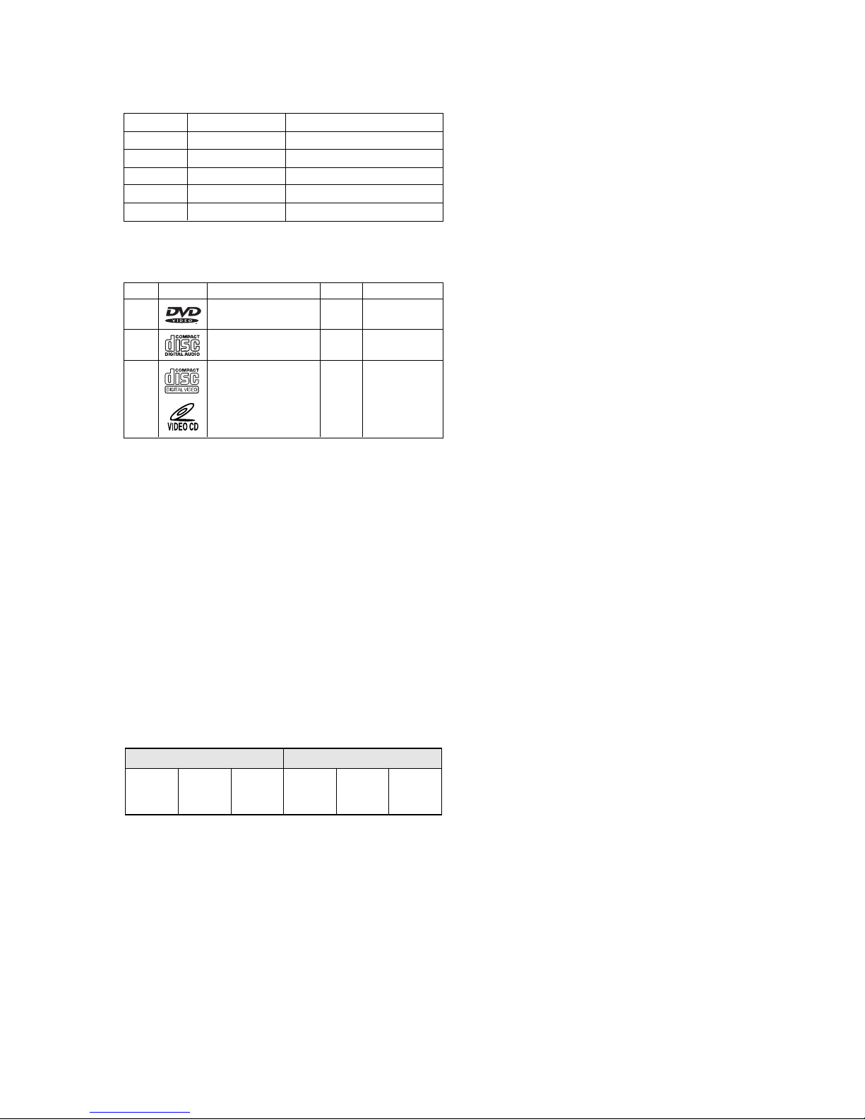
Discs played
DVD video disc ............................................... 12 cm single sided, single layer
12 cm single sided, double layer
12 cm double sided, single layer
12 cm double sided, double layer (one layer per side)
8 cm single sided, single layer
8 cm single sided, double layer
8 cm double sided, single layer
8 cm double sided, double layer (one layer per side)
Compact disc
(CD-DA, Video CD) ......................................... 12 cm, 8 cm
Video system .................................................... PAL (625/50) / NTSC (525/60)
Audio system ................................................... Linear PCM audio
MPEG 1/2 audio
Dolby Digital (AC-3)
DTS audio (Digital output only)
Video output
Line output level .............................................. 1.0 Vp-p / 75 ohms, unbalanced
RCA pin Jack x 2
S1-output level ................................................. Y output: 1.0 Vp-p / 75 ohms unbalanced
C output: 0.3 Vp-p / 75 ohms (PAL)
0.286 Vp-p / 75 ohms (NTSC)
4 pin mini DIN x 1
Color different output level ............................... Y output: 1.0 Vp-p / 75 ohms unbalanced
CB, CRoutput: 0.7 Vp-p / 75 ohms
RCA pin Jack x 3 (/F1, /K1, /S1, /U1)
R/G/B output .................................................... R/G/B output: 0.7 Vp-p 21-pin SCART connector x 2 (/N1B)
Audio output
Line output ....................................................... 2.0 Vrms / 330 ohms
RCA pin Jack x 2 system
Digital audio output
Optical output ................................................... Optical connector x 1
Coaxial output .................................................. 0.5 Vp-p / 75 ohm RCA pin Jack x 1
DVD Iinear audio characteristics
Frequency response ........................................ 4 Hz-22 kHz (Fs = 48 kHz)
4 Hz-44 kHz (Fs = 96 kHz)
S/N ratio ........................................................... More than 110 dB (Fs = 48 kHz / 24 bit PCM)
Dynamic range ................................................. More than 100 dB (Fs = 48 kHz / 24 bit PCM)
Total harmonic distortion ................................. Less than 0.0025% (Fs = 48 kHz / 24 bit PCM)
CD audio characteristics:
Frequency response ........................................ 4 Hz - 20 kHz (EIAJ)
S/N ratio ........................................................... More than 110 dB (EIAJ)
Dynamic range ................................................. More than 100 dB (EIAJ)
Total harmonic distortion ................................. Less than 0.0025% (EIAJ)
Pickup ............................................................... Wavelength: 655 nm (DVD)
Wavelength: 790 nm (CD)
Power requirements ........................................ 120V AC, 60 Hz (/U1)
100V AC, 50 / 60 Hz (/F1)
230V AC, 50 Hz (/N1)
220V AC, 50 Hz (/K1)
220 - 230V AC, 50 / 60 Hz (/S1)
Power consumption ........................................ 22 W (standby mode = approx 5 W, power off = 0 W)
Operation temperature .................................... 5 °C - 35 °C
Operation humidity range ............................... 5% - 90% (no condensation)
Dimensions ....................................................... 440 (W) x 87 (H) x 304 (D) mm (excluding protrusions)
Weight ............................................................... 4.0 kg
Supplied accessories
Auido / Video cable .......................................... x 1
D-BUS remote cable ........................................ x 1
Remote control unit .......................................... x 1
Batteries ........................................................... x 2
• For improvement purposes, specifications and design are subject to change without notice

1-2
2.1 Video performance (/N1 only)
1 2
2
2
5
5
4
4
3
6
Map of DVD Regions
135791113151719
21
2 4 6 8 10 12 14 16 18 20
2. 1. 1 SCART
Pin No. TV (OUT) Pin No. AUX (IN)
Pin 1 Audio R out : 2Vrms Pin 1 Audio R out : 2Vrms
Pin 2 Audio R in : 2Vrms Pin 2 Audio R in : 2Vrms
Pin 3 Audio L out : 2Vrms Pin 3 Audio L out : 2Vrms
Pin 4 GND Pin 4 GND
Pin 5 GND Pin 5 GND
Pin 6 Audio L in : 2Vrms Pin 6 Audio L in : 2Vrms
Pin 7 Blue out/C in Pin 7 Blue in/C out
Blue : 0.7Vpp ±0.1V into 75 Ohm *1 Blue : 0.7Vpp ±0.1V into 75 Ohm *1
C : 300mVpp ±30 into 75 Ohm *2 C : 300mVpp ±30 into 75 Ohm *2
Pin 8 function switching out <2V : TV Pin 8 function switching in<2V : DVD
>5/<8 : asp.ratio 16 : 9 DVD/AUX >5/<8 : asp.ratio 16 : 9 AUX
>9.5/<12 : asp.ratio 4 : 3 DVD/AUX >9.5/<12 : asp.ratio 4 : 3 AUX
Pin 9 GND Pin 9 GND
Pin 10 not connected Pin 10 not connected
Pin 11 Green out:0.7Vpp ±0.1V into 75 Ohm *1 Pin 11 Green in:0.7Vpp ±0.1V into 75 Ohm
Pin 12 not connected Pin 12 not connected
Pin 13 GND Pin 13 GND
Pin 14 GND Pin 14 GND
Pin 15 Red/C out Pin 15 Red/C in
Red : 0.7Vpp ±0.1V into 75 Ohm *1 Red : 0.7Vpp ±0.1V into 75 Ohm *1
C : 300mVpp ±30 into 75 Ohm *2 C : 300mVpp ±30 into 75 Ohm *2
Pin 16 fast switching out <0.4V into 75 Ohm=CVBS/S-Video Pin 16 fast switching in <0.4V into 75 Ohm=CVBS/S-Video
1</<3 into 75 Ohm=RGB 1</<3 into 75 Ohm=RGB
Pin 17 GND Pin 17 GND
Pin 18 GND Pin 18 GND
Pin 19 CVBS/Y out : 1Vpp ±0.1V *1 Pin 19 CVBS/Y out : 1Vpp ±0.1V *1
Pin 20 CVBS/Y in : 1Vpp ±0.1V *1 Pin 20 CVBS/Y in : 1Vpp ±0.1V *1
Pin 21 GND Pin 21 GND
*1 : 100% White *2 : Burst Level *3 : color bar(chroma level : 75%)
What are "regional codes"?
Motion picture studios want to control the home release of movies in different countries because theater releases arenit
simultaneous (a movie may come out on DVD in the US when itis just hitting screens in Europe). Therefore they have
required that the DVD standard include codes which can be used to lock out the playback of certain discs in certain geo-graphical
regions. Players sold in each region will have that regionis code built into the player. The player will refuse to play
these "region coded" discs which are not allowed in the region. However, regional codes are entirely optional. Discs without
codes will play on any player in any country. Some studios have already announced that only their new releases will have
regional codes. There are six regions:
1. United States and Canada 2. Europe and Japan
3. Far East (except Japan & China) 4. South America and Oceania
5. Africa and the Middle East 6. China (except Hong Kong)
2. CONNECTION FACILITIES

1-3
3. INFORMATIONS
REGION CODE
THE DISCS THAT THE DV7000 CAN HANDLE
The following discs can be played back with a DV7000.
Note: The regional code of the discs must meet to the regional
code of the DV7000.
DVD INFORMATION
Below is a glossary of the new terms related to DVD.
Title:
A disc may have more than one story/movie on it, so each
story/movie is called a "title".
For example, if there are 2 movies on the disc, they are
separated into Title 1 and Title 2.
Chapter:
A title may also be separated into chapters.
For example, a movie (title) may be separated into 3 scenes
(chapters).
Subtitles:
DVDs are recorded with up to 32 different subtitle languages.
If a disc has more than one subtitle language, you can select
the subtitle language that you want to read.
Soundtrack language:
DVDs are recorded with up to 8 different soundtrack languages.
If a disc has more than one language, you can select the
soundtrack language that you want to listen to.
Multi-angles:
On some DVDs, scenes have been filmed from different angles
(up to a maximum of 9). On these discs, you can select the
angle that you want to watch. Please refer to the DVD's manual
to see which scenes have multi-angles.
Cancelling password for parental press the DIMMER button
and hold for 10 seconds while the player is stopped.
disc mark playback capability size side
DVD Audio/Video 12 cm single/double
8 cm
CD Audio 12 cm single
8 cm
12 cm
VCD Audio/Video single
8 cm
VERSION REGION CODE COUNTRY
/FXX 2 JAPAN
/KXX 6 CHINA
/NXX 2 EUROPE
/SXX 3 SINGAPORE/HONGKONG
/UXX 1 USA/CANADA
Title 1 Title 2
Chapter
3
Chapter
1
Chapter
2
Chapter
3
Chapter
1
Chapter
2

1-4
4. SERVICING HINT
DVD test disc (NTSC) ALMEDIO TDV-540
SERVICE TOOLS
Audio signals disc 4822 397 30184
Disc without errors (SBC444)+
Disc with DO errors, black spots and fingerprints (SBC444A) 4822 397 30245
Disc (65 min 1kHz) without no pause 4822 397 30155
Max. diameter disc (58.0 mm) 4822 397 60141
Torx screwdrivers
Set (straight) 4822 395 50145
Set (square) 4822 395 50132
13th order filter 4822 395 30204
DVD test disc (PAL) 4822 397 10131
SERVICE HINTS

1-5
5. DISASSEMBLY
1. Open the tray and remove the escutcheon (050B).
REMARK : If the tray doesn't work, put a small
screwdriver into the hole as shown in picture
and slide the knob. Then the tray comes out.
After the first centimeter it is possible to pull
the tray out by hand. (see fig.1)
2. Remove 6 screws and remove the top cover.
3. Remove a top right side screw on the power supply PCB
and remove the GND lug wire.
4. Remove 3 connectors of the wire harness from (or to )
front panel assembly.
5. Remove 2 screws of left and right side of the front panel
assembly.
6. Remove the front panel assembly.
7. Remove the retainer on the DVD mechanism.
8. Remove FFC and wire harness from the DVD main PCB
which mounted under the DVD mechanism.
9. Remove 4 screws and remove DVD mechanism module.
Fig. 1

1-6
STOPPER TUB
6-1. Removal of the TRAVERSE MECHA.
6-1-1. Removal of the MECHANISM BLOCK
1) Turn the unit's power on and press the "EJECT" button to
eject the DISC TRAY.
2) Disconnect the power cord and remove the DISC CLAMPER
BLOCK.
3) Completely remove the DISC TRAY by pulling it outwards
while pulling up both of the stopper tabs alternately.
Fig. 6-1
4) Disconnect the two flat cables from the P803 connectors
and one flat cable from the P808 connector on the MAIN
PCB.
5) Disconnect the P807 connector on the MAIN PCB.
6) Remove the four a retaining screws and remove the
MECHANISM BLOCK from the chassis.
Fig. 6-2
A SCREW
6. REPLACEMENT OF PRINCIPAL COMPONENTS
6-1-2. Removal of the TRAVERSE MECHA.
1) Remove the four b screws on the MAIN PCB and then
disconnect the P800 connector on the MAIN PCB.
Fig. 6-3
2) Short the laser diode protection circuit on the PICK UP
BLOCKÕs flexible cable with solder as shown.
Caution
To protect the laser diode from damage caused by high voltage
static electricity, a laser diode protection circuit has to be
shorted before disconnecting the flexible cable (P200 connector
on the MECHANISM PCB). It is recommended that you put
solder on the top of the soldering iron as shown in Fig. 3-5
then short the circuit at once.When you replace theTRAVERSE
MECHA., be sure to connect the P200 connector before
removing the solder at the shorted parts.
B SCREW
P200
SOLDER
Fig. 6-4
Fig. 6-5

1-7
3) Carefully disconnect the two connectors (P500, P600) and
the two flat cables (P200, P300) on the MECHANISM PCB.
Fig. 6-6
4) Using tweezers, release the four retaining HOOKs of the
TRAVERSE MECHA. from the rubber insulators being
careful not to damage the rubber insulators.
Fig. 6-7
5) Remove the TRAVERSE MECHA. from the MECHANISM
BLOCK.
6) Reassemble in the reverse order for installation. Never
remove the solder on the flexible cable before connecting
the P200 connector on the MECHANISM PCB.
6-2. Replacement of the SPINDLE MOTOR
Because the SPINDLE MOTOR position is very critical, jitter
adjustment should be performed after replacement.
1) Disconnect the P300 connector on the MECHANISM PCB.
2) Insert a Philips type screw driver into the hole on the TURN
TABLE of the SPINDLE MOTOR and remove the two
screws.
6-3. Replacement of the PICK UP BLOCK
Replacement of the PICK UP BLOCK itself is not
recommended because its azimuth adjustment is very
critical and requires a special jig. If PICK UP BLOCK
replacement is necessary, replace with an entire
TRAVERSE MECHANISM only.
P200
P300
P600
P500

1-8
7. SERVICE MODE
FLD, LED TEST
1. Press the mains switch (POWER BUTTON) while
depressing the PAUSE button and STOP button.
2. Status will be on the TEST mode 1 and FL display shows
<TEST 1>.
3. Press the NEXT button, then Standby LED will be light
ON and FLD shows <LED 1>.
4. Press the NEXT button again, then Surround LED will be
light ON and FLD shows <LED 2>.
5. Press the NEXT button again, then all segments of FLD
will be light ON.
6. Press the NEXT button again, then each segments of
FLD will be light ON by press by press. (17 forms)
7. Finally FLD shows <KEY 0 0 0 0>, it will be in
“BUTTON (KEY) TEST MODE”.
8. If press some button on the front panel, FLD shows a
code of that pressed button.
9. If press the PAUSE button and STOP button
simultaneously while FLD shows <KEY 0 0 0 0>. The
status will be in “REMOTE CONTROL TEST MODE”and
FLD shows <RC6 000000>.
10.If press some button on the remote controller, FLD shows
a code of that pressed button.
11.Press the NEXT button again, then the version number of
the main microprocessor (IC600 on the DVD main PCB)
will be shown on the FLD.
12.Press the NEXT button again, then the version number of
the slave microprocessor (QF01 on the front PCB) will be
shown on the FLD.
13.Press the NEXT button again, then the status will be #2.
<TEST 1> mode. In case of finish the <TEST 1> mode,
press the mains switch (POWER BUTTON).
How to EEPROM all clear
1. Press the mains switch (POWER BUTTON) while
depressing the PLAY button and STOP button.
2. Status will be on the TEST mode 2 and FL display shows
<TEST 2>. After a couple of seconds FL display shows
<TEST2 OK>.
3. Press the PLAY button, PAUSE button and STOP button
simultaneously.
4. FL display shows <TEST OK>, then power off the mains
switch (POWER BUTTON). EEPROM should cleared.

1-9
Type version confirmation
1. Power ON the DVD player. The FL display must be
shown <NO DISC>.
2. Pressing the button and button simultaneously.
3. FL display shows product versions as follows.
.
4. Release buttons. Then FL display shows <NO DISC>
and status will be in usual mode.
Type Version setup
1. Press the mains switch (POWER BUTTON) while
depressing the STOP button and SHUFFLE button.
2. The FL display shows <E2P ALL EUR> after a couple of
seconds.
3. Type versions can be changed by pressing button
and button.
4. Memorize the version by pressing PLAY button.
5. The FL display shows <VERIFY OK> after a couple of
seconds.
6. Power OFF the mains switch.
DISPLAY VERSIONS
[ USA ] /U1B, /U1G
[ ] /N1B, /N1G
[ HK S ‘PORE ] /S1G
[ CHINA ] /K1B, /K1G
[ J A PAN ] /F1B, /F1N
[ NO REGION ] Incorrect setup.
EUROPE
VERSIONS DISPLAY
/F1B, /F1N [ E2P ALL JPN ]
/U1B, /U1G [ E2P ALL USA ]
/N1B, /N1G [ E2P ALL EUR ]
/S1G [ E2P ALL HK ]
/K1B, /K1G [ E2P ALL CHN ]
/A1B
(no release)
[ E2P ALL AUS ]
[ E2P ALL EUR ]
[ E2P ALL USA ]
[ E2P ALL JPN ]
[ E2P ALL HK ]
[ E2P ALL CHN ]
[ E2P ALL AUS ]
Press button
Press button
Press button
Press button
Press button
Press button

1-10
8. ELECTRICAL ADJUSTMENT
8-1. DVD JITTER ADJUSTMENT
1. Stick the provided small round sticker (0.1 mm thickness) at
the innermost position of a DVD disc as shown and make a
swayed DVD disc.
Fig. 8-2
2. Play back the swayed DVD disc and press the F.F button
repeatedly until the pickup block reaches the outermost
position of its movable range. Next, press the PAUSE button.
3. Set the oscilloscope to the DC input mode and connect it to
the TP201 (HOT) and the TP102 (D.GND) on the MAIN
PCB.
4. Adjust the a screw and b screw alternately so that the AC
and DC level of the waveform is minimum. (DC level should
be less than 1.8 V, AC component should be minimum.)
Fig. 8-3
NOTE: If the SPINDLE MOTOR is replaced, this jitter
adjustment should be performed for proper performance.
8-2. SLICE LEVEL ADJUSTMENT
1. Play back an ordinary DVD disc (single side, one layer) and
press the F.F button repeatedly until the pickup block reaches
almost the center position of its movable range.
2. Set the oscilloscope to the DC input mode and connect it to
the TP201 (HOT) and the TP102 (D.GND) on the MAIN
PCB.
3. Adjust the VR202 so that the DC level is minimum. (The DC
level should be less than 1.8 V)
8-3. CD TRACKING BALANCE
1. Set the VR110 at its center position prior to the adjustment.
2. Connect an oscilloscope to the TP150 (TE) on the MAIN
PCB.
3. Play back an ordinary CD-disc and then set it to the PAUSE
mode. If the play mode does not be engage, turn the VR110
at ±15 degrees. If the play mode does still not be engage
even when the VR110 is turned at ±15 degrees, turn the
VR110 at ± 30 degrees and try it again.
4. Observe the waveform and adjust it so that the level A of the
waveform is the same as level B.
Fig. 8-4
Fig. 8-1
TP107
TP105
P800
TP300
VR120
VR121
TP120
VR110
VR202
P807
TP201
P804 P803
JITTER ADJ
SCREW B
JITTER ADJ
SCREW A
Signal recorded side
STICKER
Less than 1.8V
minimum
A
B
500mV

1-11
8-4 AS Adjustment
CAUTION :
Do not see the laser pick-up! Cover the laser pick-up unit
while AS adjustment.
Adjustment point : VR120, VR121
Test point : TP107(+), TP120 (+) TP105 (GND)
Equipment : Digital Multi Meter (DC voltage)
1. Press the mains switch (POWER BUTTON) while depressing
the PLAY button and STOP button.
2. Status will be on the TEST mode 2 and FL display shows
<TEST 2>. After a couple of seconds FL display shows
<TEST2 OK>.
3. Press the button. Then the FL display shows <E3 02>
and the status will be in AS adjustment mode.
4. Measure the DC voltage at the test point TP107.
5. Press the button again. Then the DVD laser will light ON
and the FL display shows <E3 00>.
6. Press the button again. Then the CD laser will light ON
and the FL display shows <E3 01>.
7. Adjust the voltage at the test point TP120 by VR121, that the
value must be same as TP107 (10mV) value measured on
#4. process.
8. Press the button twice of time. Then the DVD laser will
light ON and the FL display shows <E3 00>.
9. Measure the DC voltage at the status DVD laser light ON.
Adjust the voltage at that status 35mV (±10mV) lower than
“CD laser light ON “status by the trim resister VR120.
10.Press the button again. Confirm the DC voltage at the
status CD laser light ON.
(DC voltage must be 35mV higher than the status DVD
laser light ON.)
11.Power OFF the mains switch (POWER BUTTON).

1-12
9. WAVEFORM
Power requirements (Refer the circuit diagram page 1-25 and 1-26)
100V AC 120V AV 220V AC
1
2
3
4
1
2
3
4
1
2
3
4
50V 5µsec 50V 5µsec 100V 5µsec
10V 5µsec 10V 5µsec 10V 5µsec
5V 5µsec 5V 5µsec 5V 5µsec
0.1V 5µsec 0.1V 5µsec 0.1V 5µsec

1-13 1-14
1.10 WARNINGS

1-15 1-16
1.11 BLOCK DIAGRAM

1-17 1-18
1.12 SCHEMATIC DIAGRAM AND PARTS LOCATION

1-19 1-20

1-21 1-22
FB SWITCH
4V
0V
RGB SWITCH
C SWI TCH
Y/CVBS SWITCH
C SWITCH
Y/CVBS SWITCH
VCR SWITCH
TV SWITCH
64
6dB
6dB
6dB
6dB
6dB
6dB
0/6dB
0/6dB
-14dB
0/6dB
-14dB
0/6dB
STEREO/
MONO
2LOUT_TV
ROUT_TV
8AOUT_RF
60
62
ROUT_VCR
LOUT_VCR
58
59 LOUT_CINCH
ROUT_CINCH
7
5COUT_VCR
YCVBSOUT_VCR
25
27
SLOW BLANK,
I/O MONITOR
SLB_TV
SLB_VCR
3YCVBS/OUT_TV
6dB
61
63
17
GOUT_TV
BOUT_TV
FBOUT_TV
1RCOUT_TV
9VOUT_RF
11 FILTER
TRAP
B_ENC
B_VCR
B_ENC
G_ENC
G_VCR
R/C_ENC
R_VCR
MUTE
R/C_ENC
C_ENC
C_VCR
MUTE
MUTE
MUTE
MUTE
MUTE
MUTE
Y_ENC
CVBS_STB
CVBS/Y_VCR
CVBS/Y_ENC
L_ENC
L_STB
L_VCR
R_ENC
R_STB
R_VCR
L_ENC
L_STB
L_TV
R_ENC
R_STB
R_TV
R/C_ENC
C_ENC
C_TV
CVBS/Y_TV
CVBS_STB
CVBS/Y_ENC
Y_ENC
43
39
56
47
53
49
45
41
38
34
52
50
36
54
48
40
42
28
30
44
46
32
18
19
FBIN_ENC
FBIN_VCR
(see Note 1)
BIN_ENC
BIN_VCR
(see Note 1)
GIN_ENC
GIN_VCR
(see Note 1)
RCIN_ENC
RIN_VCR
(see Note 1)
CIN_ENC
CIN_VCR
CIN_TV
YCVBSIN_ENC
YCVBSIN_VCR
CVBSIN_STB
YCVBSIN_TV
YIN_ENC
LIN_ENC
LIN_STB
LIN_TV
LIN_VCR
RIN_ENC
RIN_STB
RIN_TV
RIN_VCR
STV6411A
STEREO/
MONO
I
2
C BUS
DECODER
SCL
SDA
21
22
64
63
62
61
60
59
58
57
56
55
54
53
52
51
50
49
17
18
19
20
21
22
23
24
25
26
27
28
29
30
31
32
16
15
14
13
12
11
10
9
8
7
6
5
4
3
2
1
33
34
35
36
37
38
39
40
41
42
43
44
45
46
47
48
ROUT_TV
GNDA
RIN_TV
V
CCA
YCVBSIN_TV
V
REF
GOUT_TV
LOUT_VCR
BOUT_TV
ROUT_VCR
LOUT_CINCH
ROUT_CINCH
CIN_TV
LIN_TV
LIN_VCR
YCVBSIN_VCR
FBOUT_TV
FBIN_VCR (see Note 1)
FBIN_ENC
ADD
SCL
SDA
V
CC12
NC
SLB_TV
NC
GNDV1
SLB_VCR
RIN_VCR (see Note 1)
GIN_VCR (see Note 1)
NC
BIN_VCR (see Note 1)
RCOUT_TV
V
CC1
CVBSIN_STB
NC
YCVBSIN_ENC
LOUT_TV
YCVBSOUT_TV
NC
COUT_VCR
NC
YCVBSOUT_VCR
AOUT_RF
VOUT_RF
GNDV3
FILTER
V
CC3
NC
GNDV2
V
CC2
NC
NC
YIN_ENC
RIN_STB
CIN_ENC
RCIN_ENC
LIN_STB
RIN_ENC
GIN_ENC
LIN_ENC
BIN_ENC
RIN_VCR
CIN_VCR
Pin Number Symbol Description
1 RCOUT_TV Red/chroma Output, to TV Scart
2 LOUT_TV Audio Left Output, to TV Scart
3 YCVBSOUT_TV Y/CVBS Output, to TV scart
4 NC Not Connected
5 COUT_VCR Chroma Output, to VCR Scart
6 NC Not Connected
7 YCVBSOUT_VCR Y/CVBS Output, to VCR Scart
8 AOUT_RF Audio (L+R) Output to RF Modulator
9 VOUT_RF Video (CVBS) Output to RF Modulator
10 GNDV3 Video Switches Ground 3
11 FILTER Chroma Trap Filter
12 V
CCV3
Video Switches Supply 3 (8V)
13 NC Not Connected
14 GNDV2 Video Switches Ground 2
15 NC Not Connected
16 V
CCV2
Video Switches Supply 2 (8V)
17 FBOUT_TV Fast Blanking Output, to TV Scart
18 FBIN_VCR (seeN ote 1) Fast Blanking Input, from VCR Scart
19 FBIN_ENC Fast BlankingInput, from Encoder
20 ADD I
2
C Bus IC Address Programmation
21 SCL I
2
C Bus Clock
22 SDA I
2
C Bus Data
23 V
CC12
Slow Blanking Power Supply (12V)
24 NC Not Connected
25 SLB_TV Slow Blanking Input/Ouput from TV
26 NC Not Connected
27 SLB_VCR Slow Blanking Input/Ouput from VCR
28 RIN_VCR (see Note 1) Red Input, from VCR Scart
29 GNDV1 Video Switches Ground 1
30 GIN_VCR (see Note 1) Green Input, from VCR Scart
31 NC Not Connected
32 BIN_VCR (see Note 1) Blue Input, from VCR Scart
33 V
CCV1
Video Switches Supply 1 (8V)
34 CVBSIN_STB CVBS Input from STB
35 NC Not Connected
36 YCVBSIN_ENC Y/CVBS Input from Encoder
37 NC Not Connected
38 YIN_ENC Y Input, from Encoder
39 RIN_STB Audio Right Input, from STB
40 CIN_ENC Chroma Input, from Encoder
41 LIN_STB Audio Left Input, from STB
42 RCIN_ENC Red/Chroma Input, from Encoder
43 RIN_ENC Audio Right Input, from Encoder
44 GIN_ENC Green Input, from Encoder
45 LIN_ENC Audio Left Input, from Encoder
46 BIN_ENC Blue Input, from Encoder
47 RIN_VCR Audio Right Input, from VCR Scart
48 CIN_VCR Chroma Input, from VCR Scart
49 LIN_VCR Audio Left Input, from VCR
50 YCVBSIN_VCR Y/CVBS Input from VCR Scart
51 V
REF
Voltage Reference Decoupling
52 YCVBSIN_TV Y/CVBS Input, from TV Scart
53 LIN_TV Audio Left Input, from TV Scart
54 CIN_TV Chroma Input, from TV Scart
55 V
CCA
Audio Switches Supply (8V)
56 RIN_TV Audio right input, from TV Scart
57 GND A Audio Switches Ground
58 ROUT_CINC H Audio Right Output, to CINCH
59 LOUT_CINCH Audio Left Output, to CINCH
60 ROUT_VCR Audio Right Output, to VCR sCart
61 BOUT_TV Blue Output, to TV Scart
62 LOUT_VCR Audio Left Output, to VCR Scart
63 GOUT_TV Green Output, to TV Scart
64 ROUT_TV Audio Right Output, to TV Scart
Notes : 1. Pins (xx_VCR) identified a s xx_AUX in STV6410A.
2. In application, all unused pins should be left open or high frequency bypassed to ground.
Q801 STV6411

1-23 1-24
TIME
TRACK
TRACK
TITLE
TOTAL
CHAPTER
FTS
SCAN
PBC
TRACK
VCD
CHAPTER
SHUFFLE
REPEAT
TITLE
A-B
Table of contents
Other Marantz DVD Player manuals

Marantz
Marantz DV4100 User manual

Marantz
Marantz DV4003 User manual

Marantz
Marantz DV-12S2 User manual

Marantz
Marantz DV8400 User manual

Marantz
Marantz DV4500 User manual

Marantz
Marantz DV-3100 User manual

Marantz
Marantz DV4500 User manual

Marantz
Marantz DV7110 User manual

Marantz
Marantz DV4360 User manual

Marantz
Marantz DV4500 User manual

Marantz
Marantz DV6500 User manual

Marantz
Marantz DV3001e User manual

Marantz
Marantz DV4200 User manual

Marantz
Marantz DV4003 User manual

Marantz
Marantz DV-3100 User manual

Marantz
Marantz DV4600 User manual

Marantz
Marantz VC5200 User manual

Marantz
Marantz DV4600 User manual

Marantz
Marantz DV-18mkII User manual

Marantz
Marantz DV4100 User manual