Marantz 4270 User manual


~
Model
4270
Stereo
2+
Quadradial
4
R
Receiver
MARANTZ
CO.,
INC.·P.O
. BOX
99·SUN
VALLEY,
CALIFORNIA·91352
A WHOLLY·OWNED SUBSIDIARY OF SUPERSCOPE INC., SUN VALLEY, CALIFORNIA 91352

WA
R A
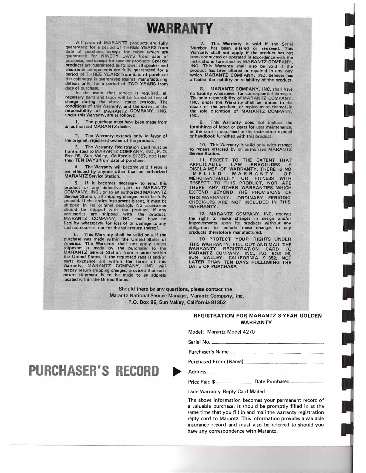
All parts of MARAN TZ
produ
cts are fully
guaranteed for a period
of
THREE
YEARS
from
date
of purchase, exce
pt
for
tubes
which are
guaranteed for NINETY DAYS from
date
of
purchase,
and
except
for
spe
aker
pr
oducts.
Speaker
produ
cts are guaranteed.as f
ollow
s: all speaker and
electron
ic
compo
nents are fully
guaranteed
for a
period of
THRE
E YEARS from
date
of purchase;
the cabinetry Is guara
ntee
d against
manufacturing
defects on ly, for a period of TWO
YEARS
from
dat
e of purchase.
In
the
event
that
service is requ ired, all
necessary
par
ts and labo r will be furnished free of
charge during the above stated periods. The
conditions of th is Warranty, and t he
exte
nt
of the
responsibilitY
of
MARA NTZ COMPANY, INC.
under this War;anty,
are
as follows:
1,
The
purchase must have
been
made
from
an
authorized
MARANTZ dealer.
2,
The
Warranty
extends
only
in favor of
the original, registered
owner
of the prod uct.
3.
The
Warranty Registration Card must be
transmitted
to
MARAN
IZ
COMPANY, INC., P. O.
Box 99, Sun Valley, California 91 352, no t later
than
TEN DAYS
from
date
of purchase..
4.
The
Warranty will
become
void if repairs
are
effected
by
anyone
other
than
an
authorized
MARANTZ Service
Station.
5. If it becomes necessary to
send
this
product
or
any
defective part to MARANTZ
COMPANY, INC., or
to
an
aut
horized MARANTZ
Serv
iceStet
ion, all shipping charges must be fullv
prepaid.
If
the
ent
ire inst
rume
nt is
sent,
it
must
be
shipped in its original package. No accessories
should be shipped
with
the
product. If
any
accessories are s
hipp
ed with the
product.
MARANTZ COMPANY, INC. shall have no
liability whatsoever for loss of
or
damage to any
such accessories,
nor
for
the
safe-return thereof.
6. This Warranty shall be valid only if
the
purchase was made within the United States of
America.
The
Warr
anty
shall not apply unless
shipment is made by
the
pur
chaser to the
MARANTZ Service
Station
from
a point within
the
United
Stat
es.
If
the
requested
repairs an
d/
or
parts exchange are
within
the t
erm
s of this
Warranty , MARAN TZ COMPANY. INC. will
prepay return shi pping charges, provided that such
return
shipment is to be made
to
an address
located
wit
hin the
United
States.
7. This
Warranty
is void if
the
Serial
Nunt>er has been
altered
or removed. This
W
arranty
shall
not
apply
if
the
product
has
not
been
co
nnec ted or operated in
accordance
with th e
instru
ctions
furn ished by MARANTZ COMPANY,
INC. This Warranty shall also be void if the
prod
uct
has been
altered
or repaired in any way
which MARANTZ COMPANY, INC. believes has
affected
the
stability
or
reliability of
the
product.
8. MARANTZ COMPANY, INC. shall have
no liability whatsoever for consequential da mages.
The sole responsibility of MARANTZ COMPANY,
INC.
under
this Warranty sha ll
be
limited to
the
repair of the prod
uct,
or rep lacement thereo f, in
the sole discretion of MARANTZ COMPANY,
INC.
9. This Wa
rranty
does
not include the
furnishings of labor or par ts for user mainte nance,
as the same is described in the instructi on
manu
al
or
handbook
furnished with this pro
duct,
10. This Warranty is valid only
with
respect
to
repairs effected by an author ized MARANTZ
Service
Station
.
11.
EXCEPT TO THE
EXTENT
THAT
APPLICABLE
LAW
PRECLUDES
A
DISCLAIMER OF WARRANTY,
THERE
IS NO
IMPLI
ED
WARRANTY
O F
MERCHANTABILITY OR FITNESS WITH
RESPECT TO THIS PRODUCT, NOR ARE
THERE
ANY O
THER
WARRANTIES WHICH
EXTEND BEYOND THE PROVISIONS OF
THIS
WARRANTY.
ORDINAR
Y PERIODIC
CHECK·UPS ARE
NOT
INCLUDED IN
THIS
WARRANTY.
12
. MARANTZ COMPANY, INC. reserves
the right to
make
chariges .ln design
and/or
i
mprovements
upon its
prod
uct
s
without
any
obligation to include these changes in any
products
theretofore
manufac
tured.
TO
PROTECT
YOUR RIGHTS
UNDER
THIS WARRANTY.
FILL
OUT AND MAIL
THE
WARRANTY
REGISTRATION
CARD
TO
MARANTZ COMPANY, INC., P.O. BOX 99,
SUN VALLEY,
CALIFORNIA
91352
, NOT
LATER THAN TEN DAYS FOLLOWING THE
DATE OF PURCHASE.
Should there be any questions, please
contact
the
Marantz National Service Manager, Marantz Company, Inc.
P.O. Box 99, Sun Valley, California
91352
~
PURCHASE
'S
RECD
0
REGISTRATION FOR
MARANTZ
3-YEAR
GOLDEN
WARRANTY
Model: Marantz Model
4270
Serial No. _
Purchaser's Name _
Purchased From (Name) _
Address _
Price Paid $
------
Date Purchased - _
Date Warranty Reply Card Mailed _
The above information becomes
your
permanent record of
a valuable purchase. It should be promptly filled in at the
same
time
that
you fill in and mail
the
warranty registration
reply card to Marantz. This information provides a valuable
insurance record and must also be referred to should you
have any correspondence with Marantz.

•
•
•
TABLE
OF
CONT
EN
TS
Connecting the 4270 2
Source Devices 4
Remote Speakers 4
Speaker Phasing 5
Speaker Placement 5
Front
Panel Features 7
Mode Switch 7
Dimension 8
SQ Decoder 8
Balance Controls 8
Selector Switch 8
Bass,
Mid
and Treble Controls 8
Monitor
Switch
for
Tape 1!Tape 2 8
Monitor
Switch
for
Tape/Source 8
Main and Remote Spkr Switches 9
Power Switch 9
Front
and Rear PhonesJacks 9
Loudness 9
Hi
Filter
Switch 9
Tuning Meter 9
Tuning 9
FM Muting Switch 10
Volume 10
Dolby
Switch 10
Record Level
(L)
(R) 10
Play Cal.
(L)
(R) 10
400Hz Tone Switch 10
Rear
Panel
Features
11
Phono Jacks
11
CD-4/
AUX
Jacks 11
Tape
Monitor
In and Tape
Monitor
Out
Jacks
11
FM Antenna Terminals
11
AM Antenna Terminal 11
FM Quadradial
Output
Jack 12
FM De-EmphasisSwitch 12
Dolby
FM Preset Level Controls 12
Muting Level Control 12
Power Mode Switch 12
Pre Out, Main In Jacks 12
Connecting an External
Amplifier
for
Rear Channels 12
Connecting an External
Amplifier
for
Front
Channels 12
Chassis
Ground Binding Post 12
Main and Remote Speakers 12
Connection
to
AC
Outlet
13
AC Convenience Outlets 13
Remote Control 13
External Decoder Connection 13
Tape Recording 13
Basic
Dolby
Process
14
Dolby
Calibration 14
Procedure
for
Playback Calibration 14
Procedure
for
Record Calibration 15
Use
of
the
Dolby
System on FM
Broadcasts 16
FM De-Emphasis Switch 16
Dolby
Mode Chart 16
Technical Description 18
General 18
Functional Description 18
Frond End 18
IF
Stages
18
Limiter
18
FM Stereo Demodulator 18
Muting
Circuit
18
AM Tuner 18
Phono
Amplifiers
19
Selector Switch 19
Monitor
(Tape/Source) Switch 19
Monitor
(Tape 1 or 2) Switch 19
Tone Control 19
Power
Amplifier
19
General Requirements 19
Installation
of
Walnut Cabinet 20
Service Notes 20
LIST F
ILL
USTRA
TI
ONS
1. Rear Panel Connection
Facilities and Adjustments 2
2. Loudspeaker System Connections 3
3. Connection Diagram 4
4. Speaker Placement 6
5. Mono Mode Sound Dispersion 7
6. 2-channel Mode Sound Dispersion 7
7. Discrete Mode Sound Dispersion 7
8. Vari-Matrix Mode Sound Dispersion 7
9.
Front
Panel
Controls and Jacks 8
10. Stereophone Plug 9
11.
FM/AM
Antenna Connections 11
12. AM Ferrite-rod Antenna 11
13. Quick-Connect Speaker Terminal 13
14. Block Diagram 17
15. Packing Instructions 20
TABLE
1.
Dolby
Mode Chart 16

GEN
ERA
LD
ESCRIPTION
Your
Marantz Model
4270
is a high-quality Stereo
2 + Quadradial 4 Receiver developed
by
Marantz,
a name famous
for
quality
in
the
audio com-
ponent industry. The Model
4270
incorporates
Marantz' exclusive
Vari-Matrix
circuit
which
sim-
ulates 4-channel sound
from
normal 2-channel
stereo programs, and is capable
of
reproducing
4-channel sound
from
any matrix-encoded source.
The
4270
will
also reproduce any discrete 4-
channel program as well as regular stereo and
monaural programs. An optional plug-in decoder
adapts the
4270
for
any specific
matrix
system
such asColumbia's SQ.
The FM
tuner
section employs an FET
for
the
RF amp and
Mixer
stage.
The IF
tuning
circuit
employs ceramic filters
of
wide
bandwidth
and
high selectivity
to
provide high sensitivity and
unparalleled interference-free operation. The
4270
incorporates a switchable 2-channel
DOLBY
system
to
reduce noise, inherent in recording
music
from
records, tape, FM broadcasts and
TV.
The FM
multiplex
circuitry
includes aphase locked
loop
Stereo-Monaural
Automatic
switching
circuit,
stereo
indicator
circuit
and a
buffer
amplifier
to
obtain
output
at
low
impedance.
Low
pass
filters
for
19KHz
and
38KHz
rejection are incorporated.
Moreover,
the
Model
4270
unit
has a
muting
cir-
cuit
that
permits pleasant FM broadcast reception
by completely eliminating inter-station inter-
ference which is usually generated at
the
time
of
selecting FM stations.
FORE
WO
RD
To obtain
opt
imum
performance and
enjoyment
from
the Model 4270, please study these instruc-
tions carefully.
Follow
the step-by-step instruc-
tions
to
obtain
maximum
performance.
The manual is divided
into
two
parts. The
first
covers installation and operation in simple, non-
technical language. The second describes the
Model 4270 in more detail
with
technical specifi-
cations and
functional
explanations.
For
quick
identification
of
the controls and
connections, references are printed in bold face
type.
AFT
ER
UNPAC
KI
NG
It
is advisable
to
save
all original packing material
to
prevent damage shouId you wish
to
transport
or ship the Receiver (refer
to
Figure 15
for
pack-
ing instructions).
Please
inspect
your
Model
4270
carefully
for
any signs
of
damage in transit.
It
has undergone stringent
quality
control
inspec-
tion
and tests
prior
to
packing, and
left
the
factory
in perfect operating
condition
.
If
the
unit
is damaged,
notify
the carrier
without
delay.
Only
the consignee may
institute
a claim
with
the carrier
for
damage during shipment. How-
ever, the Marantz Company
will
co-operate
fully
in such an event. Save
the
damaged carton as
evidence
for
inspection by the carrier.

CONN
E
CTING
THE
4270
The
4270
can be used as a stereo or 4-channel
Receiver. When using
the
4270
as a stereo unit,
the
POWER MODE Switch on
the
rear panel
should be placed in
the
70Wx2 mode.
The
instructions contained in this manual are to be
followed
for
both
stereo or 4-channel operation;
however, for stereo operation,
the
front
channels
alone will apply.
1. Using a balanced and shielded
300
Ohm cable,
connect
an FM
antenna
to
the
4270
as shown
in Figure 11.
2. Using No. 18,
or
heavier, lamp cord (zip cord),
connect
main speakers
to
the
4270
as follows:
LEFT
FRONT
SPEAKER
4270
- or
GND
or
NEG
or
COMM
or 0 to MAIN
SPEAKERS
FRONT
L-
+ or
HOT
or
POS
or 1 to MAIN
SPEAKERS
FRONT
L+
RIGHT
FRONT
SPEAKER
4270
- or
GND
or
NEG
or
COMM
or 0 to MAIN
SPEAKERS
FRONT
R-
+ or
HOT
or
POS
or 1 to MAIN
SPEAKERS
FRONT
R+
LEFT
REAR
SPEAKER
4270
- or
GND
or
NEG
or
COMM
or 0 to MAIN
SPEAKERS
REAR
L-
+ or
HOT
or
POS
or 1 to MAIN
PSEAKERS
REAR
L+
Figure
1.
Rear
Panel
Connection
Facilities
and
Adjustments
RIGHT
REAR
SPEAKER
4270
- or
GND
or
NEG
or
COMM
or 0 to MAIN
SPEAKERS
REAR
R-
+ or
HOT
or
POS
or 1 to MAIN
SPEAKERS
REAR
R+
CAUTION: When using
the
4270
in
the
70 Wx 2
mode,
do
not
use 4 Ohm speakers -
use 8 Ohms or higher.
3. Using shielded
audio
cables with
phono
plugs,
connect
your
record player
to
the
4270
as
follows:
RECORD
PLAYER
4270
LEFT
OUTPUT
to
PHONO
L
RIGHT
OUTPUT
to
PHONO
R
4. If a discrete 4-channel playback device (0-8
cartridge player, 4-channel reel-to-reel player,
CD-4 discrete disc demodulator, etc.), is to be
engaged in
the
system, make connections be-
tween
the
device and
the
4270
using shielded
audio
cables with
phono
plugs.
DISCRETE
4·CHANNEL
4270
PLAYBACK
DEVICE
LEFT-FRONT
or LF or
CHANNEL
1 or
TRACK
1 to
FRONT
CD·4/AUX
L
LEFT
·REAR
or
LR
or
CHANNEL
2 or
TRACK
2 to
REAR
CD-4/AUX
L
RIGHT-FRONT
or
RF
or
CHANNEL
3 or
TRACK
3 to
FRONT
CD
·4/AUX R
RIGHT-REAR
or
RR
or
CHANNEL
4 or
TRACK
4 to
REAR
CD-4/AUX
R
2

I
II
II
REAR
SPEAKER
SySTEM
R{PEAT
WIRIN
G
AS FOR FRONT sPEAKER SYSTEM
LEFT
Figure
2.
Loudspeaker
System
Connections
5. Using shielded audio cables with
phono
plugs,
connect a discrete 4-channel
tape
recorder
to
the
4270
as follows:
DISCRETE
4-CHANNEL
4270
TAPE
RECORDER
LEFT-FRONT
OUTPUT
or LINE
OUT
to
FRONT
TAPE
MONI-
TOR
IN L
LEFT-REAR
OUTPUT
or
LINE
OUT
to
REAR
TAPE
MONI-
TOR
IN L
RIGHT-FRONT
OUTPUT
or
LINE
OUT
to
FRONT
TAPE
MONI·
TOR
IN R
RIGHT-REAR
OUTPUT
or
LINE
OUT
to
REAR
TAPE
MONI-
TOR
IN R
LEFT-FROIH
INPUT
or LINE IN to
FRONT
TAPE
MONI-
TOR
OUT
L
LEFT-REAR
INPUT
to
LINE
IN to
REAR
TAPE
MONI-
TOR
OUT
L
RIGHT-FRONT
INPUT
or
LINE
IN to
FRONT
TAPE
MONI-
TOR
OUT
R
3
RIGHT-REAR
INPUT
or LINE IN to
REAR
TAPE
MONI-
TOR
OUT
R
6. Pull
the
AM ferrite-rod antenna
out
as shown
in Figure 12.
7.
Set
the
controls and switches as follows:
FRONT
L-R
BALANCE
REAR
L-R
BALANCE
FROI\lT·REAR
BALANCE
MODE
DIMENSION
BASS
and
TREBLE
Controls
VOLUME
MAIN
SPKR
REMOTE
SPKR
FM
MUTING
MONITOR
(TAPE/SOURCE)
HI
FILTER
LOUDNESS
DOLBY
400Hz
TONE
POWER
8. Plug
the
4270
into
the
AC wall outlet.
9. Turn
the
POWER Switch ON.
10. Select
the
desired program source by setting
the
SELECTOR Switch
to
appropriate posi-
tion.
Mid
position
Mid
position
Mid
position
VARI·MATRIX
Mid
position
Mid
position
Minimum
(fully
counter-
clockwise)
ON
(in)
OFF
(out)
ON
(in)
SOURCE
(out)
OFF
(out)
OFF
(out)
OFF
OFF
(out)
OFF
(out)

I
I FRONT
RIGHT
REAR
I
lEFT
REAR
RIGHT
IIFRONT
LEF
T
f RONT
11. If
phono
is selected,
put
on a stereo record.
If FM is selected,
tune
to
a stereo broadcast.
12. Increase
the
VOLUME control to a comfort-
able listening level.
Your
complete
4-channel
or
stereo system is
now
operative, and
you
may
experiment
with
the
vari-
ous controls to discover
their
effects.
The remainder
of
this manual explains
how
to
use
your
system most effectively.
SOURCE DEVICES
2-channel
A stereo record player may be
connected
to
the
PHONO jacks.
High level 2-channel playback devices (tuner,
tape
player, record player with equalized high
level
output,
etc.) may be connected
to
the
FRONT TAPE MONITOR and CD·4/AUX IN-
PUTS.
~
00
IS:]
lS5
00
2·CHANNEL
TAPE RECORDER
2·CH TAPE
RECOR.DE~
MAT8£
CONNECTED TO THE
Ff
~Or4
T
lUT
,o\HD RIGHT CHANNEL TERM.lMAl S
TAPE t
@) ,@
~
I
00
1D
1D00
OO
!SJ
ISJOo
4·CHANNEL
TAPE RECOROER
TAPE 2
.
~
RIGHT
1l£J
lS:l
1
1£S5
EB
I
000000
I IREAR
LEFT
REAR
TAPE DECK
4·CHANNEL RIGHT
4-channel
Discrete 4-channel playback devices (0-8 cartridge
player, 4-channel reel-to-reel player, CD-4 discrete
disc demodulator, etc.) may be connected to
the
CD-4/AUX, TAPE MONITOR 1 or TAPE MONI-
TOR 2
input
jacks.
REMOTE SPEAKERS
The
4270
can
accommodate
both main and
remote speaker systems. A second group of
four
speakers may be set up in
another
room.
Connect these
four
remote speakers
to
the
RE-
MOTE SPEAKERS terminals as you did
the
main speakers.
The
MAIN
and
REMOTE SPKR Switches on
the
front
panel now permit activation of MAIN
and/
or REMOTE groups of loudspeakers.
NOTE: Do
not
use
4-0hm
speakers if main
and
remote
speakers are
to
be used simulta-
neously. Use 8- or
16-0hm
speakers only.
@l
r RIGHT
OUTPUT ®l
RECORD PlAYER
I
10
a 'I
2-CHANNEL
8
.TRAC~
TAPE PLAYER
1001SJ
1S300
~~
LD
IDI
2·CHANNEL
I,
'000
TAP1:
PLAYER
0.8
TAPE
PlAYER 2·C"1 DEVICi. MAYBE
CONNECTED
TO THEfRONT LEFTANDRIGHT
CHANNEL
TERMINAlS
~
00
1SJ
rs:300
00
ISJ
IS:l
00
4-CHANNEL
TAPE PLAYER
00
?!
CO·..
DEMODULATOR
Figure
3.
Connection
Diagram
FRONT
LEFT
FRONT
RIGHT
REAR
LEFT
REAR
4

SPEAKER PHASING
To assure
the
best 4-channel or
Stereo
separation
and frequency response,
the
following tests will
verify
that
all
four
speakers are
correctly
phased.
1.
After
the
speakers are
connected
to
the
4270,
place all
four
speakers in
the
center
of
the
room.
2.
Set
MODE Switch
at
MONO. Play a record
(or radio or tape) with strong bass tones,
at
a
low volume level. Center
the
FRONT L-R
and REAR L-R BALANCE controls.
Set
FRONT-REAR BALANCE
control
at
extreme
FRONT position.
3. Position
the
front
(left and right) speakers
about
six inches apart, face-to-face. Listen,
particularly
to
the
apparent
loudness of
the
bass tones.
4. Next,
turn
off
all power,
but
do
not
disturb
the
volume,
tone
or balance settings. Reverse
connections on
the
right-front speaker only.
Turn
on
the
power, and listen again. If
the
bass
tones
now seem louder
than
in (3),
you
have corrected
the
phasing between
the
front
(left
and
right) speakers. If
the
bass
tones
now
sound
softer,
then
turn
off
all power and
re-connect
the
right-front speaker as you first
had it
connected
.
5. Now check phasing between
the
two
left
(front
and rear) speakers.
Set
both
FRONT
L-R
and
REAR L-R BALANCE
controls
at
extreme
L
position, and
set
FRONT-REAR BALANCE for
equal loudness from
the
two
speakers. Posi-
tion
the
two
speakers face-to-face,
about
six
inches
apart
, and listen for bass as in (3).
6.
Turn
off
power. Experimentally reverse con-
nections only on
the
left-rear speaker. Use
the
connection which gives
the
"best"
bass, as
in (4).
7. Last, check phasing between
the
two
rear
(left
and
right) speakers. Center
both
FRONT
and REAR BALANCE controls.
Set
FRONT-
REAR BALANCE control
at
extreme
REAR
position. Position
the
two
rear speakers face-
to-face as before. Listen for bass.
8. Turn
off
power. Experimentally reverse con-
nections
only
on
the
right-rear speaker. Listen
again
to
determine
the
"best
" bass
method
of
connecting
the
right-rear speaker. All speakers
will
then
be in phase, and you
may
use all
controls normally.
9. Once having phased
your
four
speakers, you
need
not
repeat
the
procedure in
the
future if
you now
code
the
speaker
connections
and/or
the
speaker cables.
Any
method
of
coding is
satisfactory, provided it enables
you,
in
the
future,
to
duplicate
your
now-correct
hookup
between speakers
and
amplifiers.
SPEAKER PLACEMENT
Experimentation will reveal
the
best
speaker
locations in
your
room.
The
placements are
shown in Figure 4.
5

LF
RF
LR
RR
LF
RF
RF
RR
LF
RF
RF
RF
RR
LR
RR
LR
LF
LF
RF
RF
RR
LR
RR
Figure
4.
Speaker
Placement
6

FRONT
PANEL
FE
lURES
MODE SWITCH
MONO
When
the
MODE
Switch
is in
the
MONO
position,
all
input
signals are
summed.
Speakers
are
driven
as
shown
in Figure 5.
Use
the
MONO
position
for
A) phasing speakers
and
B) playing a
monaural
source
such
as TV
audio,
AM
radio
or
monaural
records
through
all
four
channels.
2 CH
When
the
MODE
Switch
is in
the
2 CH
position,
left-front
and
left-rear
inputs
are
summed.
Right-
front
and
right-rear
inputs
are
summed.
Speak-
ers are driven as
shown
in Figure 6.
Use
the
2 CH
position
for
playing
regular
stereo
records
without
synthesizing
rear channels.
DISCRETE
When
the
MODE
Switch
is in
the
DISCRETE
position, each
input
signal goes
to
its respective
output
channel.
Speakers
are
driven as
shown
in Figure 7.
Use
the
DISCRETE
position
for
A) playing dis-
crete
4-channel
sources
such as 0 -8
cartridges
or
CD-4 records,
and
B) playing 2-channel
stereo
programs
through
front
speakers
only
.
VARI-MATRIX
When
the
MODE
Switch
is in
the
VARI-MATRIX
position,
rear
input
signals
are
internally
discon-
nected.
Left-front
and
right-front
inputs
feed
left-front
and
right-front
speakers, as in
the
DIS-
CRETE
MODE. Rear
channel
signals
are
"syn-
thesized"
or derived
from
the
left-front
and
right-
front
input
signals.
The
characteristics
of
the
LEFT FRONT RIGHT FRONT
SPEAKER
SPEAKER
<,
",~'
"
.....
'"'" ,
\ LF +
RF+
"~(''''LF
+ RF + I
\ LR +
RR
'" -.LR +
RR
'
\ '
,\ I '
\ ' \,
,,'
\I
I "\
/\
:\
I ,
,\
I LF + RF +
.....
"'LF
+ RF
+'
I LR +
RR
'>
~
LR +
RR
\
I ...
........
\
~,.
....................
...
.....
,"
"""
LEFT
REAR
RIGHT
REAR
SPEAKER
SPEAKER
,NPUT
SI
GNAL
OESIGNA.
TlONS
;
lFo<lEfT
fRONT
.
Rf-RIOHT
fRONT
LA-lEn
REAR .
RR-RIGHT
REAR
Figure
5.
Mono
Mode
Sound
Dispersion
rear
channel
signals
are
varied
by
the
DIMENSION
control.
Speakers
are
driven as
shown
in Figure 8.
LEFT FRONT
SPEA
KER
,,"
.......................
".
,.
<,
,"""
I
" LF + LR
.....
" RF.+
RR
I
,
.,."
<,
I
\ , I '
\ I \
,I
, I
\I
"
" I 1\,
I \ ,
I ,
I \
I
.....
'"
,
I
,>"
. \
, LF + LR ",'" ..... RF +
RR
\
'"
"",'"
...................
.-
LEFT
REAR
RIGHT
REAR
SPEAKER
SPEAKER
INPUT
SI GNA L D ESIQN A,n ON S:
IF
-L EFT
fRONT
, RF - RIGH T FRONT
LA-LEFT
R
fA
R.
RR"RI
GHT REAR
Figure
6. 2-
channel
Mode
Sound
Dispersion
,
I
I
. I
I
I
\ I
\I
1\
I ,\,
\
RR
" \
LEFT
REAR
RIGHT
REAR
SPEAKER
SPEAKER
LEFT FRONT RIGHT FRONT
SPEAKER
SPEAKER
\\ \ \ ,
\ \ '
,,'
I'
I \
I
I
I
I LR
I
IHf"VT
SIQNAl
DESIGNATIOHS
:
Lf-lEfT
FRONT
,
AF-RIGHT
FRONT
l R- l EFT REAR ,
Aft-RIGHT
REAR
Figure
7.
Discrete
Mode
Sound
Dispersion
LEFT FRONT
SPEAKER
..
","
'"
'"
\ '...... "'" I
\ LF ..
~(",
RF I
\ '"
~/
\ I
, I
\ , \ I
, I
\I
't
1\
" I
1\\
I \
,'DERIVED '" DERIVED\
I FROM LF ...
,>~
FROM LF \
I AN
DR
E"''''
.........
ANDRF
\
"."/'
<;
.
...
.....
.-"
...
LEFT REAR RIGHT
REAR
SPEAKER SPEAKER
INPlIT
SIGNAL
DESIGNATIOJlIS :
V-LEFT
FRONT
,
RF-RIGHT
fRONT
lA-lEfT
AEAA ,
nA-HIGHT
REAR
Figure
8.
Vari·Matrix
Mode
Sound
Dispersion
7

__
4li'a"
.~
•
~
~270
dZu.a-
~~2,.(J~A14/~
•
grr
....
~
co.
~
..
ooscrc
¥5
M
"""",,
~
••
"':;
)-
'
";;'
.
~
D
~
.
~
1'
~ ::::
;
-
,,'':;
'
.
-
'
~'
~
"
l
".
'
Tarc
''''''''
.. O
Ol.
.
...
~
l
~
:lJ
#10
'"
I
~
""
~.
_
·
~
CO
Dr:
..
-I '
.~
·n
.
..
.r:-J
I'nDn
"or
doll."
••
I• .::l o r
~.,.,
. d ' .....
enwio"
DIMENSION
The
DIMENSION
control
is operative
only
when
the
MODE
Switch is set to the
VARI-MATRIX
position. This control optimizes
the
4-channel
VARI
-MATRIX
effect.
SO DECODER
With the MODE Switch on
sa
DECODER, any
rear
input
signals
to
the
4270
are
internally
dis-
connected. The rear channel
outputs
are, in-
stead, derived
from
front
channel signals which
have been processed by the plug-in decoder. The
characteristics
of
these derived rear channel
out
-
puts are determined by the
type
of
plug-in
decoder.
UseSO DECODER position
only
with
an optional
plug-in decoder installed.
Without
this
opt
ional
decoder, there
will
be no
output
when the
MODE
Switch is set
to
the
SO DECODER position.
BALANCE
CONTROLS
The Model
4270
has three
BALANCE
controls:
FRONT
L-R,
REAR
L-R and
FRONT-REAR.
The
FRONT
L-R slide knob adjusts the balance
between the
front
channels. The
REAR
L-R
slide
knob
adjusts the balance between
the
rear
channels. The
FRONT-REAR
slide knob adjusts
the balance between the rear and
front
pairs
of
channels. Balance adjustments
must
be carried
out
in
the
MONO mode. To balance the
front
channels,
first
set
the
FRONT-REAR
control
all
the way
to
the
FRONT
to
silence the rear speakers
while you adjust the
FRONT
L-R
BALANCE
control. To balance the rear channels, move the
FRONT-REAR
control
all the way
to
REAR,
and then adjust
REAR
L-R
BALANCE.
Now
you
are ready
to
adjust the
FRONT-REAR
control
for
the most pleasing overall balance.
_
~
"'
'1
_~
~
I.
..
....
t'n.d
'r.b'.
...01
........
p
.........
•
Figure
9. Front
Panel
Controls
-
and
Jacks
SELECTOR SWITCH
The SELECTOR Switch selects the program
source
for
listening or recording. The switch
can select any
of
six sources:
AM,
FM, PHONO,
CD-4/
AUX,
TAPE
1 and
TAPE
2.
BASS,
MID
AND
TREBLE
CONTROLS
These controls are used
to
adjust
the
tonal
balance
of
program material
to
suit
your
indi-
vidual listening preference. The
bass,
midrange
and treble responses are adjusted by dual-con-
centric,
friction
-coupled controls. With BASS,
MID
and
TREBLE
controls
set at the center posi-
tion,
frequency response
of
the
amplifier
becomes
flat.
The smaller (outer)
knob
adjusts the response
of
the
front
audio channels, while the larger (inner)
knob adjusts the rear audio channels.
Turn the knobs clockwise
to
boost, or counter-
clockwise
to
attenuate its respective frequency
range.
MON
ITOR
SWITCH FOR TAPE
1/TAPE
2
This switch
assigns
the TAPE/SOURCE
MONI·
TOR Switch
to
either TAPE 1 or TAPE 2.
MONITOR
SWITCH FOR TAPE/SOURCE
When
the
MONITOR
(TAPE/SOURCE) Switch is
placed in
"TAPE"
(in) position, the signals con-
nected
to
the tape
input
jacks (asselected by the
MONITOR
TAPE 1, 2 Switch)
will
be played
back.
To play
the
tape recorder connected
to
the
TAPE
MONITOR
1 or TAPE
MONITOR
2 jacks,
8

or to
monitor
the tape on a three-head recorder
during recording, place the
MONITOR
(TAPE/
SOURCE) pushswitch in the
"TAPE"
(in) posi-
tion.
During recording, the MODE Switch should be
in the DISCRETE,
VARI-MATRIX
or SO DE-
CODER positions. This applies the source signal
unchanged, directly
to
the tape outputs. '
To record a discrete 4-channel source on a 2-
channel recorder,
put
the MODE Switch in the
2 CH position.
Leave
the TAPE/SOURCE
button
in the SOURCE (out) position while recording.
This
will
feed the sum
of
the
left-front
and left-
rear inputs
to
the
left-front
TAPE
MONITOR
OUT jack, and the sum
of
the
right-front
and
right-rear inputs
to
the
right-front
TAPE MONI-
TOR
OUT
jack.
To record any type
of
source on a monaural
recorder,
put
the MODE Switch in
the
MONO
position.
Leave
the TAPE/SOURCE
button
in
the SOURCE (out) position while recording.
MAIN
AND
REMOTE SPKR SWITCHES
These switches select the loudspeaker terminals
to which audio power is fed. The
MAIN
and
REMOTE groups
of
loudspeakers may be operat-
ed separately or simultaneously. With both
speaker switches in the
"out"
position, all loud-
speakers
are disconnected. The signal at the
FRONT and REAR PHONES jacks is
not
affected
by the
MAIN
and REMOTE SPKR Switches.
NOTE: When using hoth
MAIN
and REMOTE
speakers
simultaneously, the combined
impedance
of
all the speakers should
not
be
less
than 4 Ohms.
POWER SWITCH
This pushswitch turns the Power on or
off.
When
the POWER Switch is
"in",
the dial lamp illumi-
nates. Be sure
to
turn
the POWER pushswitch
off
before plugging or unplugging the power cord.
FRONT
AND
REAR
PHONES
JACKS
These jacks accept a standard 3-conductor phone
plug employed
with
standard stereo or 4-channel
headphones. When using 2-channel headphones,
insert the plug
into
the
FRONT
PHONES jack.
When using 4-channel headphones, insert the
front
plug
into
the
FRONT
PHONES jack and
the rear plug
into
the
REAR
PHONES jack.
Either high- or low-impedance headphones may
be used.
LOUDNESS
When listening at
low
levels, set this switch
"in"
.
The LOUDNESS Switch boosts
bass
and treble
tones to compensate
for
the human ear's lack
of
response to those frequencies at
low
volume
levels.
HI
FILTER
SWITCH
With this pushswitch set
"in",
the High Fre-
quency Filter
suppresses
high frequency noise,
such
as
"scratch"
from
worn phonograph records
and tape "hiss". The
filter
will
also slightly
reduce high frequencies in the program material.
When the program does
not
have high frequency
noise, the HI
FILTER
pushswitch should be
"out"
.
TUNING
METER
The Model 4270 is equipped
with
two
meters,
aSIGNAL-STRENGTH Meter and anFM
TUNING
Meter. The SIGNAL-STRENGTH Meter indicates
the signal-strength
of
any AM or FM broadcast.
The FM
TUNING
Meter operates on
FIVI
only
and
indicates correct station tuning. The
SIGNAL-
STRENGTH Meter acts
as
a Dolby Calibration
Meter when the
DOLBY
Switch is in any position
other than
"OFF".
TUNING
AM:
For
optimum
AM
reception, tune to the
desired station. Then, rock the
TUNING
knob
slightly back and
forth
until
the maximum
reading is obtained on the SIGNAL-STRENGTH
Meter. The FM
TUNING
Meter is
not
used
for
AM.
FM: Set
the
SELECTOR Switch to
"FM"
and
tune to the desired station. Then, slowly rock
the
TUNING
knob back and
forth
until
the FM
TUNING
Meter points to the center scale posi-
tion.
,.--
---
--
LEFT CHANNEL
COM MON
L..-.----RIGH
T
CHAN
NEL
Figure
10. Stereophone
Plug
9

FM
MUTING
SWITCH
When tuning
to
FM broadcasts
with
the FM MUT-
ING
Switch in its
"in"
position, the muting
circuit
will
eliminate
inter
-station noise. To prevent
muting
of
very weak stations along
with
the
noise, the
muting
function
may be turned
off
by
releasing the FM
MUTING
pushswitch
to
the
"out"
position.
VOLUME
This
control
regulates volume
of
all
four
channels
simultaneously.
DOLBY
SWITCH
This switch sets the
Dolby
noise-reduction
circuit
for
record or playback and also switches the
Meter Mode
from
AM or FM SIGNAL-STRENGTH
to
DOLBY
CAL
LEVEL,
or vice-versa. With the
DOLBY
Switch placed in
"OFF"
position, the
Meter
will
be used as a
SIGNAL-STRENGTH
Meter; in all other positions,
as
a
DOLBY
CAL
LEVEL
METER.
DOLBY
FM: This position is used
for
listening
to
Dolbyized FM broadcasts. The
Dolby
FM
level has been pre-adjusted at the factory.
PLAY:
This position is used
to
play back a
Dolbyized source (except FM).
OFF:
With this position, the
Dolby
circuit
IS
by-passed and the
input
signals are
directly
applied
to
both TAPE
MONITOR
OUT
jacks
and amplifiers.
RECORD I: For making a Dolbyized recording
from
an in-coming
"flat"
(non-Dolbyized) signal.
When the
MONITOR
Switch is in the SOURCE
(out) position, the
"flat"
signal
will
be heard.
When the
MONITOR
Switch is in the TAPE (in)
position, the Dolbyized signal
from
the tape
will
be heard.
RECORD
II:
For making a
"flat"
(non-Dolbviz-
ed) recording
from
an in-coming
Dolby
ized signal.
Regardless
of
the position
of
the
MONITOR
SWitch, a
"flat"
signal
will
be heard.
Refer to the
Dolby
Mode Chart on page 16.
RECORD
LEVEL
(L)
(R)
These knobs control the record level
of
the signals
to be recorded through the
Dolby
unit.
Adjust
the knobs so
that
the Level Meter pointers
of
the tape recorder do
not
exceed the OVU level.
PLAY
CAL.
(L)
(R)
These knobs adjust the playback
outputs
from
a
tape deck
to
the proper
Dolby
level.
400Hz
TONE
SWITCH
This is used
for
calibration
of
the record
input
level
of
the tape deck. When the switch is
depressed, the
built
-in oscillator operates and a
sine wave signal
output
of
580mV
will
be applied
to
the
four
TAPE MOI\IITOR
OUT
jacks.
10

R
ARPA
E FEATUR
ES
PHONO JACKS
These
two
jacks are intended for use with
magnetic cartridges requiring a
standard
47,000
Ohm resistive load. If a hum is heard when
playing a record,
try
reversing
the
polarity of
the
turntable
power plug. If this is ineffective,
connect
a separate ground wire from
the
turn-
table or record changer
to
the
CHASSIS GROUI\ID
binding post of
the
4270.
CD-4/AUX JACKS
These jacks are for
connection
of any 4-channel
high level
equipment
source. Manufacturers may
use
different
terminology
for
the
four
channels,
and care should be exercised to avoid confusing
the
signal channel terminations.
The
following
are examples of 4-channel
nomenclature
equiva-
lents:
LEFT
FRONT
LF-LF-CHANNEL - 1
TRACK
1
LEFT
REAR
LR-LB-CHANNEL - 2
TRACK
2
RIGHT
FRONT
RF-RF-CHANNEL - 3
TRACK
3
RIGHT
REAR
RR-RB-CHANNEL - 4
TRACK
4
TAPE MONITOR IN AND TAPE MONITOR
OUT JACKS
These jacks are for
the
connection
of a 2-channel
or 4-channel
tape
recorder.
(Refer
to
"SOURCE DEVICES", page 4.)
1\",
ANTENNA FM
ANfENaA
[iii]
[iii]
,, , ,
,,
: ' ,,
300
0 UNSHI
ElDED
~
TRAN
SMISSIO
N
lI
UE • ,
( TW I N L.EAD )
::
SINGLE WIRE
n
.1
ANTENNJl.. f M ANTENNA
[iii]
,,
·, ,
·
·,
, .
.,:
-
....
_ SHIELD 750 COAX.
~SHIElO
3
00
0 SHIELDED TRANSMISSfON
TRANSMISSION LINE LINE
~
FM ANTENNA TERMINALS
These terminals
connect
to
an FM
antenna.
For
best FM reception, Marantz recommends a Log-
Periodic
antenna
mounted
on a good quality
rotor
system.
For
rural areas, it is recommended
that
a local dealer be consulted
about
antenna
installation and lightning arrestor protection. A
master
antenna
system is
not
recommended for
use with
your
Model
4270;
such systems are
usually designed expressly for television reception
and frequently suppress FM signals
before
distri-
bution. In addition, master
antenna
systems
often
severely limit
quality
FM reception. Where
outdoor
antennas
are prohibited or inconvenient,
use a simple form
of
300
Ohm TV " rabbit
ear"
antenna
or
the
simple ribbon-type folded dipole
antenna
supplied with
the
4270.
Both are prac-
tical and will give satisfactory resuIts in primary
signal areas.
Your Model
4270
will
accept
either
a
75
Ohm or
300
Ohm
antenna. (See Figure 11.)
The
300
Ohm
antenna
cable
should
be
connected
to
the
two
terminals marked FMon
the
ANTENNA
terminal. When using 75
Ohm
coaxial antenna
cable,
connect
its shield
to
the
" G" terminal, and
its inner or
center
conductor
to
either of
the
FM
terminals.
AM ANTENNA TERMINAL
This terminal
connects
to
an AM antenna.
The
4270
is equipped with a ferrite-rod
antenna
for
AM reception
and
it will give satisfactory results
in primary signal areas. However, an
outdoor
Figure
11.
FM/AM
Antenna
Connections
Figure
12.
AM
Ferrite-rod
Antenna
11

antenna
will
provide
better
reception.
Two
single
wires are required
to
make an AM
outdoor
antenna. First, connect one end
of
a single
wire
to
the AM
ANTENNA
terminal on the rear
panel, and the
other
end at a very high position
outdoors. Next, connect the
other
single
wire
between
the
"G"
terminal and an earth ground
(such as a water pipe).
(Refer
to
Figure 11.)
FM
QUAD
RADIAL
OUTPUT
JACK
In antic
ipat
ion
of
discrete 4-channel stereo broad-
casts,
your
Model
4270
is equipped w
ith
an FM
QUAD
RADIAL
OUTPUT
jack. The signal avail-
able at this jack is the unequalized
output
of
the
FM
discriminator
.
It's
frequency response cha-
racteristics and signal level are ideal
to
drive any
4-channel adaptor. This jack can also be used as
a simple white-noise generator
for
frequency
response check
of
loudspeakers
or
amplifiers.
For
this
application, release FM
MUTII\lG
Switch
of
the Model
4270
in FM mode and
tune
off
from
any
FM signal.
FM DE-EMPHASIS SWITCH
Selects
75J.LS
or
25J.LS
FM DE-EMPHASIS
for
accurate reception
of
Dolbyized FM signals.
DOLBY
FM PRESET
LEVEL
CONTROLS
These
factory
-adjusted controls govern FM out-
put
level
to
the
DOLBY
circuit. These controls
are
for
the
use
of
a
qualif
ied technician
only.
MUTING
LEVEL
CONTROL
Adjusts
the
threshold
of
the inter-station
muting
circuit.
Turning
this
control
counter
-clockwise
w
ill
lower
the threshold
to
permit
reception
of
weak signals.
POWER
MODE
SWITCH
Switches
from
25 watts x 4 operation
to
70 watts
x 2. In
the
2-channel mode,
only
the
front
speaker terminals are used.
BE
CERTAIN
THAT
THE
UNIT'S
POWER
SWITCH IS
OFF
BEFORE
OPERATING
THE
POWER
MODE
SWITCH.
NOTE: When operating
the
unit
in
the
70W x 2
mode, all speaker terminals are "above
ground".
Consequently, the use
of
any switching
or
testing
system
which
employs a
common
ground
will
activate
the
l
imiting
circuits and should therefore
be avoided.
PRE
OUT,
MAIN
IN
JACKS
For
normal operation, these jacks are inter-
connected
with
the supplied jumpers. When
connecting an external
unit
(equalizer, reverbera-
tion
unit,
etc.), remove
the
jumpers and connect
the PRE
OUT
jacks
to
the external
unit's
inputs.
In
turn,
connect
the
external
unit's
outputs
to
the
MAIN
IN jacks.
It
is possible to create a higher powered 4-channel
system by adding an external
amplifier.
If
the
external
amplif
ier has
less
than 70 watts x 2,
it
should be used
to
drive
the
rear speakers.
If
the
external
amplifier
has more than 70 watts x 2,
it
should be used
to
drive
the
front
speakers. In
each
case,
the
rear panel POWER
MODE
Switch
should be set
to
the
70Wx2
position.
CONNECTING
AN
EXTERNAL
AMPLIFIER
FOR
REAR
CHAI\II\IELS
To use an external
amplifier
for
the rear chan-
nels, connect the
REAR
PRE
OUT
jacks
to
the inputs
of
the external amplifier. In
turn,
connect
the
rear speakers
to
the
output
terminals
on the external
amplifier.
The
4270
will
then
supply
the
power
for
the
front
speakers and the
external
amplifier
will
supply the
power
for
the
rear speakers.
CONNECTING
AN
EXTERNAL
AMPLIFIER
FOR
FRONT
CHANNELS
To use an external
amplifier
for
the
front
chan-
nels, connect
the
REAR
PRE
OUT
jacks
to
the
FRONT
MAIN
IN jacks. Connect
the
rear speak-
ers
to
the
FRONT
speaker terminals on the
4270
.
Then, connect the
FRONT
PRE
OUT
jacks
to
the
inputs
of
the external
amplifier.
In
turn,
connect
the
front
speakers
to
the
output
terminals on the
external
amplifier.
The
4270
will
then supply
the power
for
the rear speakers and
the
external
amplifier
will
supply the power
for
the
front
speakers.
CHASSIS
GROUND
BINDING
POST
Permits connection
of
the
ground
wire
from
a
turntable
or
other
component
to
reduce hum.
MAIN
AND
REMOTE
SPEAKERS
Sixteen
quick
-connect terminals are provided
eight
for
main speakers and eight
for
remote
speakers. (Refer
to
"CONNECTING
THE
4270"
and
"REMOTE
SPEAKERS".)
12

Terminals
work
as shown in Figure 13.
1)
Press
terminal in
2) Insert speaker wire
3)
Release
terminal
CONNECTION TO AC
OUTLET
With the
front
panel POWER pushswitch
"OUT",
plug the line cord
into
an electrical
outlet
supply-
ing the proper voltage.
CAUTION:
DO
NOT
PLUG
YOUR
MODEL
4270
INTO
A DC
OUTLET,
AS
SERIOUS
DAMAGE
WI
LL
OCCUR.
AC CONVENIENCE
OUTLETS
Two
AC outlets, one switched and one unswitch-
ed, are provided on the rear panel
to
supply
power
to
associated components
of
the system
(tape recorder, record player, etc.), The maxi-
mum power available
from
the SWITCHED and
UNSWITCHED AC
OUTLETS
is
100
Watts and
200 Watts, respectively.
REMOTE
CONTROL
The REMOTE
CONTROL
connector and switch
are intended
for
use
only
with
the optional
Model RC-4 Remote Control. The REMOTE
CONTROL
Switch
assigns
control
of
loudness,
balance and volume
to
the optional
RCA
Remote
Control. WHEN
THE
RC-4 IS
NOT
USED,
THE
REMOTE
CONTROL
SWITCH
MUST
BE
IN
THE
LOCAL
POSITION.
EXTERNAL
DECODER CONNECTION
A pocket on the
bottom
of
the
chassis
will
ac-
commodate Marantz 4-channel decoders, such as
the Model SQA-1. For use,
follow
the instruc-
tions supplied
with
the optional decoder.
TAPE RECORDING
Instructions
for
connecting a recorder and playing
back a tape are given in "SOURCE DEVICES",
page
4.
To record, select the desired program source,
using the SELECTOR Switch. Put the recorder
connected
to
the TAPE
MONITOR
OUT
jacks
"1
or
2"
in the record mode.
For additional
information,
refer
to
MODE
SWITCH on page 7, and
MONITOR
SWITCH
on page 8.
3. RELEASE THE
TERMINAL
Figure
13.
Quick-Connect
Speaker
Terminal
2. INSERT
SPEAKER
WIRE
INTO TERMINAL
1. P
RESS
ENDOF
TERMINAL IN
13

BASIC
DOLBY
PROCESS
The
Dolby
system increases the level
of
low-level,
mid
- and high-frequency signals during recording
and reduces
the
level
of
these signals by an
identical
amount
during playback. As a result,
the playback signal is identical
to
the original
source signal,
but
the level
of
background noise
generated
by
the tape recorder is greatly reduced.
A Dolbyized FM broadcast has already been
subjected
to
the
first
phase
of
the noise reduction
process before
it
is transmitted. When these
signals
pass
through the
Dolby
playback
circuitry,
the mid- and high-frequency noise, is greatly
reduced.
OLBV
CAL
IBRATI
ON
The purpose
of
the
following
adjustments is
to
achieve the proper
Dolby
levels by calibrating
the recording and playback signals being applied
to the
Dolby
processors
to
a standardized level
of
580mV.
The Model
4270
is capable
of
processing
Dolby
signals
from
sources other than a tape recorder
(AUX,
PHONO, FM, ETC.).
NOTE:
It
is possible
to
use the
Dolby
system
for
recording and playing back tapes through
your
system
without
using a standard alignment tape.
Procedures
for
making
your
own
Dolby
Align-
ment Tape are asfollows:
1. Thread a blank tape
onto
your
recorder
(or insert a cassette).
2. Set
the
400Hz TONE Switch to the
"ON"
(in) position.
3. Set
your
recorder's
monitor
switch
to
the
source position.
4. Set
your
recorder's record levels
to
0 VU.
5. Commence recording. Record about 45
se-
conds
of
the
tone. This tape you have just
made is used
to
calibrate the Marantz
Dolby
circuit
with
the
recorder.
However, a
Dolby
recording made on
your
re-
corder using
the
calibrated tape you have
just
made may
not
necessarily be compatible
with
the
Dolby
circuits in a
different
recorder
or
systems.
Therefore,
for
universal
compatibility,
Marantz
offers a
Dolby
standard alignment tape which
will
make all
of
your
Dolby
recordings universal
with
any other
Dolby
system. These tapes are
available in
the
standard reel-to-reel, cassette and
8-Track formats.
If
you desire one
of
these tapes,
enclose a check or money order
for
$4.95
for
each tape desired (California residents add 5%
sales
tax). Be sure
to
specify which
format
is
desired. Mail
to:
MARANTZ
NATIONAL
PARTS
P. O. Box 99
Sun Valley, California
91352
NOTE: The
Dolby
system can be used
with
most types
of
tape recorders. However,
it
can-
not
be used
with
a recorder
utilizing
Automatic
Recording Level system (A LC).
PROCEDURE FOR
PLAYBACK
CALIBRATION
1.
Turn
on the Model
4270
and
your
recorder.
2. Set the
DOLBY
function
switch on the
Model
4270
to
the
PLAY
position.
3.
If
your
recorder has a SOURCE!TAPE
(MONITOR)
Switch, set
it
to
"TAPE".
4. Load
the
Dolby
standard alignment tape.
5. Play
the
Tape.
6.
If
your
recorder does
not
have
output
level controls, proceed
to
step 9.
7. When your recorder has
output
level controls
and the meters on
the
recorder read play-
back level, adjust
the
controls
until
the
meters read
"OVU".
Then proceed
to
step 9.
8.
If
neither 6
nor
7
apply
to
your
recorder,
set
the
output
level controls
to
about
2/3
of
full
output.
9.
Adjust
the
PLAY
CAL
controls
(left
and
right) on the
4270
to
the
DOLBY
LEVEL
reference on
the
SIGNAL-STRENGTH
Me-
ter. To adjust the
left
PLAY
CAL
control,
place
the
METER
Switch
to
the
"OUT"
position. To ad
just
the right
PLAY
CAL
control,
place
the
METER
Switch
to
the
"IN"
position.
10. You have
now
properly
calibrated the
Dolby
Playback Level. From this
point
on, do
not
change
your
recorder's
output
level
contro
ls
or
the
Model 4270's
PLAY
CAL
controls.
14

Since the calibration is extremely stable and
should
not
have
to
be repeated (except
to
period-
ically check
it),
we
suggest
that
you mark
the
settings
of
your
recorder's
output
level controls
with
a felt-tipped pen. Doing so
will
enable
you
to
easily reset the controls
if
they are
inadvertantly moved.
PROCEDURE FOR RECORD
CALIBRATION
Before proceeding
with
the record calibration,
be certain
that
the playback adjustments have
been performed. DO
NOT
CHANGE TH E POSI-
TIONS OF THE RECORDER'S
PLAYBACK
LEVEL
CONTROLS
(if
any) OR
THE
4270's
PLAY
CAL
CONTROLS.
In
the
event a record calibration is performed by
the use
of
TAPE MOI\IITOR 1 IN and
OUT
Jacks
of
Model 4270,
shift
the SELECTOR switch
to
TAPE 2 after turning on a 400Hz TONE knob.
On the other hand, when the record calibration is
conducted by the use
of
TAPE
MONITOR
2 IN
and
OUT
Jacks,
shift
the SELECTOR switch to
TAPE 1. Home-position the SELECTOR switch
after the calibration.
For Recorders
with
Three Heads
1. Thread a blank tape
onto
your
recorder (or
insert a cassette).
2. Put the 4270's
DOLBY
Switch in the
"PLAY"
position.
3. Put both the 4270's and the recorder's moni-
tor
switches in
the
"Tape"
position.
4. Put the 400Hz TONE Switch in
the
"ON"
(in) position.
5. Commence recording.
6. Adjust the recorder's record level controls
so the tone
will
deflect the 4270's
SIGNAL-
STRENGTH
lVIeter
to
the
"DOLBY
LEVEL"
mark.
For Recorders
with
Two
Heads
1. Thread a blank tape
onto
your
recorder (or
insert a cassette).
2. Put the 4270's
DOLBY
Switch in
the
"OFF"
position.
3. Put the 400Hz TONE Switch in the
"ON"
(in) position.
4. Commence recording.
5. Adjust
the
recorder's record level controls
to
deflect the recorder's meters
to
OVU.
6. Record the tone
for
approximately 15
sec-
onds. I
7. Stop the recorder and rewind
it
to the begin-
ning
of
the
tone recording. I
8. Put the 4270's
DOLBY
Switch in the
"PLAY"
position. I
9. Put the recorder in the play mode and play
back the tape.
10. Note the level reading on the 4270's SIG-
NAL-STRENGTH Meter. To check the left •
channel level,
put
the METER Switch in the
"OUT"
position. To check the right chan-
nel level,
put
the METER Switch in the
"1
N"
position. The object is
to
adjust the
recorder's record level controls so the play-
back level achieved indicates
"DOLBY-LEV-
EL"
on the 4270's SIGNAL-STRENGTH
Meter.
11.
If
the Meter indicates
"DOLBY
LEVEL"
,
calibration is completed.
12. A)
If
the Meter indication is above the
"DOLBY
LEVEL",
repeat steps 2 - 11,
but
decrease
the record level in step 5
to
slightly below OVU on the recorder's
VU Meters.
B)
If
the Meter indication is below the
"DOLBY
LEVEL",
repeat steps 2 - 11,
but
increase the record level in step 5
to
slightly above OVU on the recorder's
VU Meters.
For all Recorders
After
the
"DOLBY
LEVEL"
has been achieved
on the SIGNAL-STREI\lGTH Meter, DO NOT
change the recorder's
input
or
output
level con-
trols or the 4270's
PLAY
CAL
controls.
Utilizing the recorder's VU Meters, proper Dolby
recording levels are adjustable by using the RE-
CORD
LEVEL
controls on the
front
panel
of
the
4270. This
only
applies when making a Dolby
recording.
Setting the level slightly
lower
than OVU
will
increase the
Dolby
effect.
CHANGING THE RECORDER'S RECORD OR
PLAYBACK
LEVELS
OR
THE
4270's
PLAY
CAL
CONTROLS WI
LL
AFFECT
THE
DOLBY
CALIBRATION
.
15

Mark
the
calibration positions on the recorder's
record and playback level controls
to
avoid the
necessity
of
re-calibrating after making a non-
Dolby
recording.
IMPORTANT:
It
will be necessary
to
re-calibrate the Dolby
levels when a change in tape
speed
has been made
or when a
different
brand or type
of
tape is used.
When the
Dolby
process is
not
desired on a re-
cording, record in the normal manner - adjusting
the record levels
with
the recorder's record level
controls. DO NOT change the 4270's
PLAY
CAL
controls.
USE OF
THE
DOLBY
SYSTEM ON FM BROAD-
CASTS
Your
Model 4270 is equipped
to
receive Dolbyiz-
ed FM broadcasts.
Most FM broadcasts do
not
currently
use the
Dolby Noise-Reduction system.
To
receive these
broadcasts, leave the
DOLBY
Switch in the
"OFF"
position. However,
if
a local station is
broadcasting a Dolbyized FM signal,
full
advan-
tage
of
the increase in signal-to-noise ratio may
be obtained by
putting
the
DOLBY
Switch in
the
"DOLBY
FM"
position. The rear panel
DOLBY
FM PRESET
LEVEL
controls are fac-
tory
-adjusted. Do
not
change the position
of
these controls.
FM DE-EMPHASIS SWITCH
This rear panel switch operates
only
when the
front
panel
DOLBY
Switch is in the
"DOLBY
FM"
position.
It
alters the frequency response
of
the FM signal. Normally, this switch should
be
left
in the
7511S
position. However,
if
the
station is broadcasting the Dolbyized signal using
a
2511S
pre-emphasis,
put
this switch in the
"25I1S" position
to
obtain
flat
FM frequency
response.
If
in doubt, call the station.
DOLBY
MODE
CHART
This chart indicates the correct
DOLBY
Switch
positions
for
various types
of
input
material.
The
input
format
is indicated in the
left
column
and the appropriate
DOLBY
Switch position,
together
with
FM DE-EMPHASISSwitch position,
is shown under the appropriate mode of opera-
tion
.
'~
De-Emphasis Dolby Switch Position
Mode Switch Listening Record
Input
Position W
ithout
Dolby With Dolby
F.M.
75J1.S
"Off"
"Off"
"Record
I"
(Normal)
F.M.
with Dolby
7511s
"Dolby
FM"
"Record
II"
"Dolby
FM" If
7511s
Pre-emphasis
the
F.M.
with Dolby
25J1.S
"Dolby
FM"
"Record
II"
"Dolby
FM" rect
25J1.S
Pre-emphasis
Non Dolbyized
sources
"Off"
(Phone, Tape, -
"Off
"
"Record
I"
Aux inputs,
"Record
I"
A.M.) terial
Dolbyized
sources (de-
rived from
"Play"
"Record
II"
"Play"
to
"Tape"
or -
"Record
II" mode.
"Aux"
inputs
etc.)
For initial calibration, utilizing
the
Dolby standard alignment tape, see detailed instructions
on Pages 14 thru 16 of this manual.
Notes :
-
there
is a
doubt
regard-
ing
the
pre-emphasis used on
transmission,
the
F.M.
station should be contacted,
where possible, to ensure cor-
position for de-emphasis
switch.
Pre-recorded tape manufac-
turers indicate when
the
rna-
has been recorded in a
Dolbyized format. Home reo
corded tapes should also be
clearly marked as
to
format,
ensure
correct
play back
Table
1.
Dolby
Mode
Chart
16
Other manuals for 4270
1
Table of contents
Other Marantz Stereo Receiver manuals

Marantz
Marantz SR7002 User manual

Marantz
Marantz 2238 User manual

Marantz
Marantz SR5015 DAB User manual

Marantz
Marantz SR7002 User manual

Marantz
Marantz NR1403 User manual

Marantz
Marantz 2240B User manual

Marantz
Marantz SR-19 User manual

Marantz
Marantz NR1403 Quick start guide

Marantz
Marantz SR9600 User manual

Marantz
Marantz 2270 User manual

Marantz
Marantz NR1607 User manual

Marantz
Marantz SR-7001 User manual

Marantz
Marantz NR1403 User manual

Marantz
Marantz 2010 User manual

Marantz
Marantz NR1603 Quick start guide

Marantz
Marantz SR7012 User manual

Marantz
Marantz SR-5001 User manual

Marantz
Marantz SR5000 User manual

Marantz
Marantz SR4023 User manual

Marantz
Marantz SR5004 User manual