March PX-500 User manual

Plasma Asher: March PX-500
User guide
(May-30, 2017)
This is a highly versatile plasma etch tool that can etch using a
direct plasma configuration (Oxygen plasma cleaner), a
downstream plasma (Remote plasma), and a directional
plasma (Reactive Ion Etch). We supply Oxygen (gas 1) and
Argon (gas 2) for use. Power can set up to 600 W, and
working pressure is controlled by gas flow. There are totally 9
programs for automatic process and can be modified by users.

Shelf configuration
Program #9 is set for chamber cleaning. User can modify the other
programs (#1-#8)
For RIE plasma(Directional):
Ground shelf upper then power shelf bottom with samples on the
power shelf. Floating not used. Pressure should be in the 0.1 - 0.5T
range. RIE is a very aggressive etch with heavy ionic bombardment.
The etch is directional and isotropic, mainly used for Oxygen plasma
cleaning and Argon plasma physical etching.
4
3
1
2
RIE PLASMA1
DIRECT PLASMA
RIE PLASMA2
DOWNSTREAM
GROUND
POWER
GROUND
POWER
FLOAT

For Direct plasma:
Power shelf upper then ground shelf bottom with samples on
the ground shelf. Floating not used. Pressure should be in the 0.5 -
1T range. This is a less aggressive etch but does include ions
but ions are not necessarily directed towards the samples. The
plasma is anisotropic.
For downstream plasma:
Ground shelf upper then power shelf in middle then floating shelf
bottom with samples on the floating shelf. Pressure should be in the
0.5 - 1 T range. In this configuration, all of the ionic activity is
contained between the powered and ground shelves and only non-
charged particles (free radicals) are able to pass through the power
shelf to the area below it. This is the least aggressive type of etch
and is typically used when samples are sensitive to ion damage.
Shelves
POWER
SHELF
FLOAT
SHELF
GROUND
SHELF

Tool Operation
1) Log on to the FOM
2) LOAD THE SUBSTRATE
Press the “MAN OP” button and then press the
“BLEED” button to vent the chamber.
When the chamber is vented (about 60 s for venting),
unlatch the chamber door and insert sample.
oPut your sample on desired shelf (see shelves
configuration above and test result in Appendix
B)
oClose and latch the chamber door.
oPress the “MAN OP” button again to activate
the automatic operation mode (“MAN OP” LED
light is extinguished for auto operation).
3) PROGRAMMING
Standard setting for parameters:
Pressure=0
END/PT= 100
BP/RP= 50 mTorr
Press the “PROGRAM” button to select your program
Press the “L DISP” button repeatedly until the “TIME”
label lights up
oPress the “SET” button to illuminate its LED light
oPress the “DECR or INCR” buttons to set the
plasma “on” time (sec) by decreasing or
increasing the time in the left display above.
oWhen the correct time appears in the display,
press the “SET” button again to extinguish the

LED light. This saves the value.
Press the “L DISP” button to light up the “POWER”
label.
oPress the “SET” button to illuminate its LED light
oPress the “DECR or INCR” buttons to set the
plasma power (Watts) by decreasing or
increasing the Power in the left display above.
oWhen the correct power appears in the display,
press the “SET” button again to extinguish the
LED light. This saves the value.
Press the “R DISP” button on the right side to illuminate
the “GAS1” label.
oPress the “SET” button to illuminate its LED light
oPress the “DECR or INCR” buttons to set the O2
(or Ar) flow rate, (% of 100 sccm), by
decreasing or increasing the value in the right
display above.
oWhen the correct flow value appears in the
display, press the “SET” button again to
extinguish the LED light. This saves the
value.
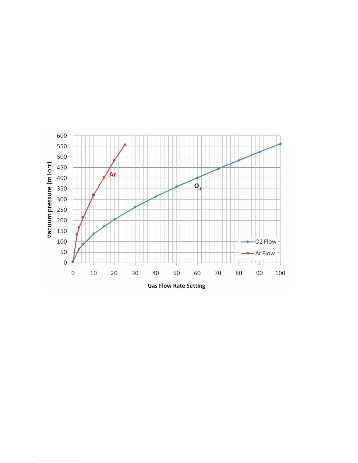
oConsult the percent O2(Ar) flow vs pressure chart
in Appendix B to determine the proper flow value
for your process pressure. The actual values may
drift somewhat over time as the vacuum pump oil
becomes contaminated, so some variance from
the table may be required as experience dictates.
4) RUNNING THE PROCESS
•Press the “START” button in the

upper left corner. This starts the
process:
oChamber is pumped down to 50 millitorr
oGas flow is started
oRF Power is turned on – Note the forward and
reflected power values on the RF power supply to
the left of the process control module. If the
reverse power is more than 50%, shut off the
system with the BIG RED EMO button and call a
staff member.
oTime counts down from your set value
oAt the conclusion of the time, the RF power and
Gas flow are turned off and the chamber is
pumped down to base pressure.
oAfter achieving base pressure, the chamber is
vented with Nitrogen for 45 seconds.
oAt the conclusion of the vent cycle, a beeper peeps
softly.
5) RETREVING THE SUBSTRATE
•At the end of the vent cycle, shut off the beeper by
pressing the “STOP” button. Open the door and
retrieve your sample. Be careful to note the
temperature of the substrate shelf as it can get hot on
long runs.
•When the sample is out, close and latch the chamber
door
•Press the “MAN OP” button and the “VAC ON” button to
pump the chamber down again. Allow the vacuum to
achieve base pressure and then shut off the “VAC ON”
valve.

Appendix A
Chamber Pressure vs Gas Flow Rate
Use this chart to decide what approximate gas flow is
needed to establish the pressure you need for your plasma.
You may have to fine adjust the flow to achieve accurate
pressure. As time goes on, the base pump pressure may
degrade and shift the lower end of this correlation curve
somewhat. Argon mass flow controller maximum flow is
250 sccm, and the Oxygen meter is 100 sccm – thus the
large difference in pressure curves.

Actual Flow Rate vs Flow Setting
This chart calibrates the flow setting to actual flow in
units of Standard Cubic Centimeters per Minute (sccm).
The Argon Mass Flow Controller maximum flow is 250
sccm, and the Oxygen meter is 100 sccm – thus the large
difference in pressure curves.

Appendix B
RIE1 1400
Direct plasma 250
RIE2 1200
Downstream
RIE1 1300
Direct plasma 660
RIE2 1500
Downstream 130
3
4
600
80
10
600
1
2
Ashing Rates for Photomask SC1827 Resist
Plasma type
500
40
0
278
Process
RF Power
(Watts)
O2 Flow
(%)
Pressure
(mTorr)
Etch Rate
(Ǻ/Min)
Ar Flow
(%)

Appendix C
Process Controller Module
The Process Controller monitors and controls the
various parameters of the process. The basic ON/OFF
portion of the control panel is shown on the left, and the
parameter input and monitor panel is shown on the right.
The machine is switched on by pressing the medium
sized green button. The big red emergency OFF button is
used to turn off the machine. The Key is a lock-out for
parameter change operations. For general use, the tool will
not be locked. The “Auto/Man” switch enables manual RF
tuning to match the plasma impedance with the output
impedance of the RF generator. The Alarm beeps at the end
of process and the volume knob sets the loudness of the
enunciator. The alarm is silenced by pushing the “STOP”
button.
The parameter input section of the control panel
consists of 4 sections. The first is the START/STOP buttons,
which do just that – start the automatic program or stop it.
The second section, “PROGRAM,” is the program selection
button. By repeatedly pushing this button you can cycle

through all 9 possible programs. When a program is
selected it is available for execution by the start button.
Parameter input is achieved through the 8 buttons in the
upper right section of the panel. The term “L
DISP” denotes the “Left Display” lights above the buttons. If
the “SET” button is pushed and the LED lights up, you can
change the numbers by repeatedly pressing either the
DECR or INCR buttons just below the SET button. The
particular parameter you are selecting is set by repeatedly
toggling the “LDISP” button until the corresponding label is
lit. The third set of 4 buttons in the upper right selects the
process gas by toggling the “RDISP” (Right Display) “SET”
button, and sets the flow in units of “% of Mass flow meter
capacity.” There are six gas sources that can be selected
by repeatedly pressing the “R DISP” button. Currently we
have two gases available – “GAS 1” for Oxygen and “GAS
2” for Argon. Pressure is determined by the flow rate as this
tool has no vacuum level throttle valve control. A table to
correlate pressure with gas flow is attached in Appendix A.
The fourth set of buttons deals with manual operation.
These are in the bottom row to the right of the “Manual”
toggle button. These buttons are active when the “MAN
OP.” light is on, and consist of the “VAC ON” button which
toggles the vacuum valve on or off; the “PRESS” button
which toggles a valve to expose the vacuum gauge to the
vacuum line; the “GAS ON” valve, which toggles the process
gas on or off; the “RF ON” button which toggles the RF
power on or off; and the “BLEED” button, which pumps the
chamber down to a minimum set point, then vents the
chamber.
CAUTION: Take care not to open the “PRESS” valve
when the pressure gauge is at vacuum and the vacuum line
is at atmospheric pressure. This will send a pressure shock

wave into the vacuum diaphragm triggering a calibration drift
and possibly causing damage to the gauge. The proper
procedure is to open the valve and wait at least 15 seconds
before opening the vacuum line to the gauge.
RF Power Generator
The RF power generator is a separate unit sitting just
to the left of the Asher system. It provides the 13.6 MHz RF
power to drive the plasma. It is remotely controlled by the
process controller microprocessor, therefore the buttons on
the front panel of the RF generator are inactive but the
power meter indicates the forward and reverse power
delivered to the plasma chamber. This meter should
indicate mostly forward power and very little reverse power.
If you notice the reverse ratio shut off the plasma with the
big red EMO button to protect the RF generator from
overheating and contact NFCF staff.
Table of contents
Popular Medical Equipment manuals by other brands

KYRA MEDICAL
KYRA MEDICAL k-tek KTEK2330 Instructions for use

Orliman
Orliman OP1183 manual

Atos Medical
Atos Medical PROVOX Measure manual

Neo G
Neo G 3D H/C1 manual

Global Halotherapy Solutions
Global Halotherapy Solutions HALO-Booth PRO MEDIUM Assembly

DeVilbiss Healthcare
DeVilbiss Healthcare 7305 Series Instruction guide