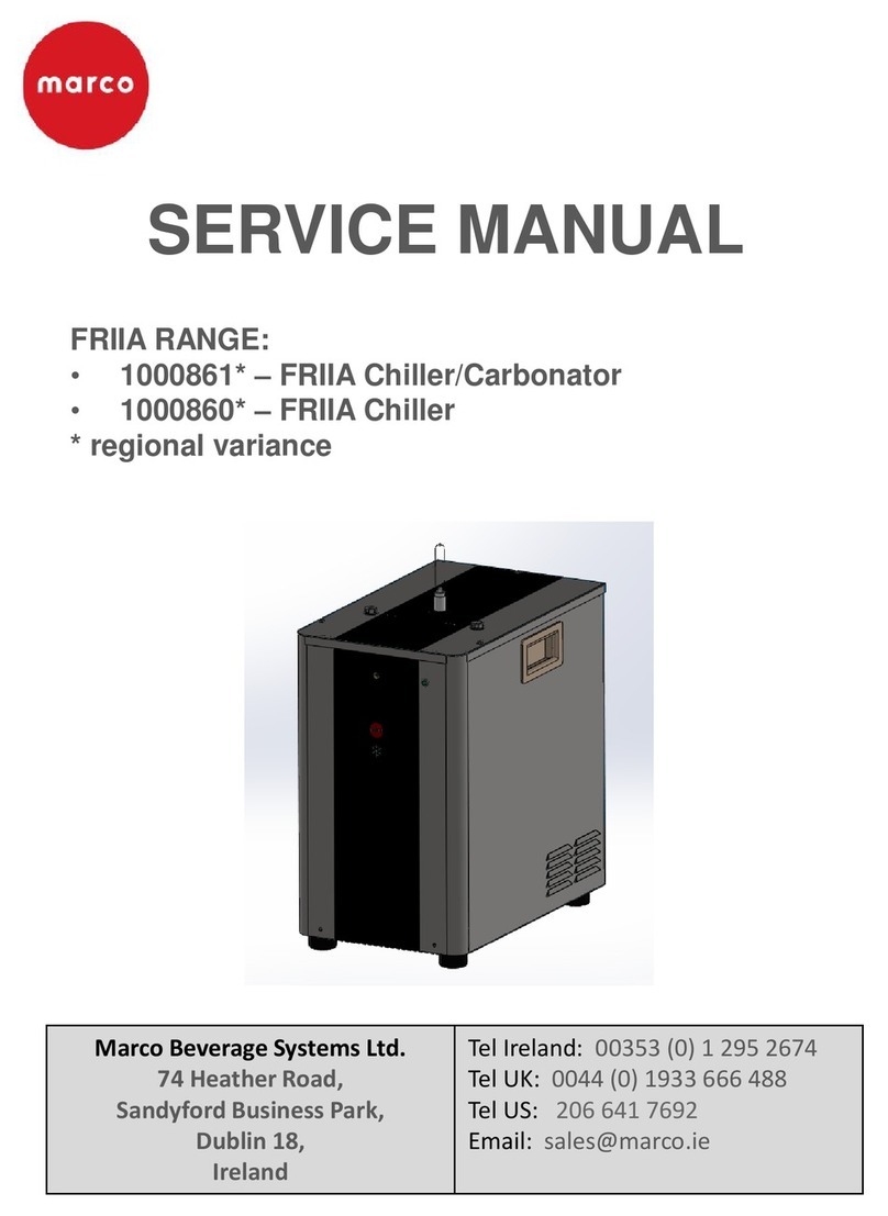
Marco FRIIA Lite User manual

Marco Beverage Systems
Research & Development
Service Manual
1
26/06/2023
Friia Lite
Service Manual
1000201* - FRIIA LITE Chiller
• 1000202* -FRIIA LITE Chiller/Carbonator
www.marcobeveragesystems.com Ireland Tel: +353 (1) 295 2674
UK Tel: +44 (0207) 2744577

2
1Table of Contents
1 Introduction 4
2 Safety Instructions 5
3Specification 6
4 Installation 7
4.1 Positioning 7
4.2 Electrical Installation 7
4.3 Plumbing Installation 7
4.4 CO2 Installation 7
4.5 Backflow Prevention 9
4.6 Thermostat Setting 9
5 Overview & Operation 10
5.1 Before Using the Chiller 10
5.2 Display 11
6 Routine Maintenance 12
6.1 Daily Maintenance 12
6.2 External Parts 12
6.3 Cleaning 13
6.4 Sanitization 14
6.4.1 Preparing the Chiller for Sanitization 14
6.4.2 Sanitising 14
7Accessing the Internal Components of the Chiller 15
7.1 How to Drain Water from the Ice bank 15
7.2 How to Remove the Top Panel 16
7.3 The Front Panel 16
7.3.1 How to Remove the Front Panel 16
7.3.2 How to Replace the Front Panel Assembly 18
7.4 The PCBs 19
7.4.1 Replacing the Display Board Assembly 19
7.4.2 Replacing the Water Leak Detection Board 19
7.5 Replacing the Pump 20
7.6 The Solenoid Valves 20
7.6.1 How to Remove the Solenoid Valve Bracket 20
7.6.2 How to Repair the Solenoid Valves 21

3
7.7 The Dustproof Net 22
7.8 The Gas Reducer 22
7.9 The Ice Bank Tank 23
7.9.1 Replacing the Cooling NTC & the Pressure Relief Valve 23
7.9.2 Replacing the Gas Board 24
7.9.3 Removing the Connectors Above the Tank 24
7.9.4 Replacing the Cooling Pump, Water Level Sensor and Sparkling Water Tank 26
7.10 Removing the Left Side Panel to Repair the Power Cable 27
7.11 Removing the Right Panel to Repair the Filter Connector Head 28
7.12 Removing the Cooling Switch 30
7.13 Accessing the Control PCB (1600406) 30
7.13.1 Repairing the Control PCB 31
7.14 Repairing the Fan (1400214) 32
8Diagnostics 34
8.1 Troubleshooting Friia Lite Chiller/Carbonator P/N 1000202 34
8.2 Troubleshooting Friia Lite Chiller P/N 1000201 35
8.3 Failure Modes 36
9Wiring Diagram 38
10 Hydraulic Diagram 39
11 Plumbing Diagram 40
12 Spare Parts 41
12.1 Spare Parts Diagram 41
12.2 Spare Parts List 42
13 Accessories 44

4
1Introduction
The information provided in this manual is intended to assist in the installation and maintenance of
the Marco FRIIA Lite System. Please read the instructions carefully to prevent accidents and ensure
an efficient installation. This manual is not a substitute for any safety instructions or technical data
affixed to the machine or its packaging. All information in this manual is current at the time of
publication and is subject to change without notice. Only technicians or service providers authorized
by Marco should carry out installation and maintenance of these machines. Marco accepts no
responsibility for any damage or injury caused by incorrect or unreasonable installation and
operation. Do not allow anyone to operate the equipment unless suitably trained. Keep the
equipment in good working order and do not allow any modifications unless authorized by the
manufacturer.
Unless otherwise stated, pictures are generic and for reference only, they are subject to technical
change without prior notice.
The manufacturer reserves the right to modify the product and the relative technical documentation
at any time and without notification and cannot be held liable for any errors or inaccuracies in the
contents of this manual.
This version of the use and Maintenance Manual describes the characteristics of the standard
production equipment as of the date of printing.
Contact Marco Beverage Systems for any technical queries or to order spare parts.
When replacing equipment parts, you are advised to use original spare parts; the manufacturer
cannot be held liable for any reduction in equipment performance or damage caused by the use of
non-original parts.

5
2Safety Instructions
• Read all instructions.
• To protect against electric shock do not immerse mains cord in water or other liquid.
• To prevent fraying of the cable, do not let the mains cord hang over the edge of a table or
counter; or touch hot surfaces.
• Do not operate any appliance with a damaged cord, plugs, or after the appliance
malfunctions or has been damaged in any manner.
• Switch off at the mains (unplug or disconnect from outlet) and turn off the water supply
when not in use and before cleaning. Allow to cool before removing components.
• The use of spares and accessories not recommended by Marco may cause damage and/or
injuries.
• Do not use outdoors. Do not place on or near a hot gas or electric burner.
• Do not use the appliance for anything other than its intended use.
• Save these instructions.

6
3Specification
Model 1000201 1000202
Description FRIIA Lite Chiller FRIIA Lite Chiller/Carbonator
Power Supply Voltage & Frequency
(V/Hz):
230V ~ 50/60Hz 230V ~ 50/60Hz
Power Consumption: 177W 220W
Cooling capacity: >12 L/h ( ΔT ≥ 10°C ) >12 L/h ( ΔT ≥ 10°C )
Pouvoir Hydrogène (PH) 6.5 ~ 8.5 6.5 ~ 8.5
Applicable Water Pressure 0.1 ~ 0.4Mpa 0.1 ~ 0.4Mpa
Room Temperature 4 ~ 38°C 4 ~ 38°C
Applicable Inlet Water TDS<350ppm TDS<350ppm
Chlorine Reduction >97.4% >97.4%
Carbonation tank Capacity / 0.45L
Volume/Gas / >2.5V/gas
Sparkling water flow rate / ≥1.8L/min
CO2 Reducer / Micro CO2 Reducer thread
ACME
Rechargeable CO2 Bottle / 60lt / 360-410gr
Cooling System Ice Bank Ice Bank
Cold Water Flow Rate ≥1.5L/min ≥1.5L/min
Cooling Power 100W 100W
Product Size 279x468x412mm (WxDxH) 279x468x412mm (WxDxH)

7
4Installation
4.1 Positioning
• The equipment must be placed on a surface capable of bearing the weight of the chiller
full of water. Install the equipment following the schematic described in this user guide.
• The chosen position must allow satisfactory ventilation; there must be a gap of at least
10 cm (3.9 in) around the back and top for ventilation.
• The equipment must not be placed close to direct or indirect heat sources (ovens,
stoves, radiators, etc.).
• The electrical connection and water supply points must be close to the equipment must
be located in such a way the power cable and water hose do not form an obstruction.
• The appliance must not be installed where water jets can be generated. Do not spray
water on the device; this could cause electric shock or fires.
• The equipment is not suitable for external use.
• The equipment must be placed so it is protected from rain and water splashes, and in a
location with the temperature appropriate to its climate class (stated in specification);
otherwise, warranty rights are forfeited, and malfunctions may occur.
4.2 Electrical Installation
• When installing the chiller, always observe the local regulations and standards.
• The chiller is supplied with a moulded power cord.
• A suitable mains power supply socket should be available within easy access of the
chiller so that it can be disconnected easily after install.
4.3 Plumbing Installation
• Ensure that the chiller is installed according to local plumbing & water regulations.
• Fit a stop valve on a cold-water line and attach a 3/8” BSP male fitting, (E.g. 3/4” x 1/2”
311 or washing machine type stop valve).
• Connect water supply lines following the installation drawings. As per installation guide
in the User Manual (starting page 8).
• Push the pipe firmly into the fittings until locked into position to avoid leaks. 15mm is
the correct depth of insertion.
• In case filter systems are used verify that they satisfy the requirements of the legislation
in force.
• The chiller has a pressure reducer in case the incoming water exceeds 3 bar.
• Turn on the water to flush any impurities, dust etc. from the inlet hose and water pipe.
• Allow several litres through. Especially for new installations.
4.4 CO2 Installation
There are two CO2 installation options with this chiller, either an inbuilt 360-410gr/60L gas cylinder
or an external CO2 cylinder.
Internal gas cylinder
Open the side door. Install the CO2 cylinder into the machine. A compatible gas cylinder to use is the
Sodastream 60L cylinder https://sodastream.co.uk/pages/co2-gas-cylinders Once the CO2 cylinder is
installed, the yellow CO2 light stops flashing on the font of the machine.

8
• External gas cylinder
The machine has an external gas connection for an 8mm hose (not provided) in the rear; you must
supply appropriate pressure gas (0.4MPa). Only use super-dry, food grade CO2 hose. Before
connecting the pressure reducer to the gas cylinder, always vent any dirt from the valve. Close the
cylinder valve after a few seconds.
The cylinder must be replaced when the needle of the reducer high pressure gauge is in the red
segment or when the CO2 light on the front of the chiller flashes.
1. Record the pressure values set on the pressure reducer, then fully close the bottle using the valve.
2. Remove the pressure reducer or disconnect the high-pressure hose from the bottle if fitted. Check
the condition of the gaskets between the reducer and the bottle, replace them if necessary.
3. Replace the CO2 cylinder by slowly opening the valve to the fully open position and check that the
pressure values are as originally set.
Gas cylinder location
To prevent the risk of injury or damage the CO2 cylinder must always be kept in a vertical position
against a wall, held in place by a chain and fixed to a bracket. Do not expose the bottle to heat
sources or very low temperatures.
Pressure reducers
There are different types of CO2 cylinder available. Always use a pressure reducer suitable for the
type of valve on the cylinder. If you use CO2, especially in a small area, ventilate the contaminated
area at once.
We advise using a Dual gauge CO2 regulator, Marco part number 1400195. Check for leaks using a
solution of soapy water.

9
1400195 (EU) - Dual Gauge CO2 Regulator 4.8bar (BS341 No8 (0.860” x 14tpi))
1860864 FEP Tubing 8mm OD for external gas supply
4.5 Backflow Prevention
This chiller must be installed with adequate backflow protection to comply with all applicable
federal, state and local codes.
4.6 Thermostat Setting
The temperature of the dispensed beverages cannot be adjusted.

10
5Overview & Operation
5.1 Before Using the Chiller
•Before connecting the chiller to the power source, let it stand upright for approximately 2-3 hours,
this will reduce the possibility of a malfunction.
•Check that all installation procedures have been carried out.
•Ensure water inlet is open.
Wait until the pump stops running before turning on gas or installing cylinder in the machine, to ensure
the gas does not block the system.
•Ensure CO2 valve is open.
•Before supplying power to the chiller check water and CO2 lines do not leak.
•Plug the chiller into a suitable socket and turn the Cooling Switch on the rear of the chiller to the ON
position.
•When the unit is on, the carbonation pump starts to fill. The carbonation device stops when it reaches
the maximum level.
•If using an external CO2 Cylinder, on the pressure reducer knob, adjust CO2 pressure to a value
between 50 and 65 PSI (350 and 450 kPa) (3.5 - 4.5 bar) This value depends on the temperature of the
water and on the ambient temperature. The temperatures correspond to the CO2 pressure.
•The chiller will take approximately 70-120 minutes to get down to temperature depending on the
temperature of your incoming water. The blue light on the front of the chiller remains flashing during
this time.
•Once the blue light stops flashing and remains solid the water is chilled and at optimum temperature.
•To enable the filling of lines, push the font buttons in the following order sparkling water, cold water
& hot water until the flows appear.
•At this point you can dispense water.

11
5.2 Display
Model 1000201 1000202
Description FRIIA Lite Chiller FRIIA Lite Chiller/Carbonator
Screen
Filter Light
Lights up to indicate the filter needs to be replaced.
Flashing indicates a shortage of water.
Cooling Light
Lights up to indicate the chiller is ready to use
(allow 70 - 120min for the chiller to get down to temperature).
Flashing indicates the compressor is ON.
Sparkling Water Light
Lights up to indicate the CO2 Cylinder is empty.
When the light is off this indicates the CO2
Cylinder is full of gas.

12
6Routine Maintenance
Maintenance should be carried out by Marco approved technicians only. Before undertaking routine
maintenance on Friia Lite disconnect the machine from mains power, water and gas supply.
6.1 Daily Maintenance
1. Water font
Clean the font nozzle and remove any residual using warm water; do not use solvents or abrasive
detergents. If needed, remove all the limestone with a food descaling solution.
2. Drip tray
Clean the drip tray and remove any residual using warm water.
3. CO2 pressure
Review pressure CO2 gauges for proper settings.
4. Power cord
Check the condition of the power cord. Replace if necessary.
6.2 External Parts
Filter and CO2 Hatch
LED Display
Electrical connection to
font
Electrical connection to
boiler (cable supplied
with font)
¼” Cold Output to Font

13
6.3 Cleaning
The exterior of these machines may be cleaned with a damp cloth and a light detergent. Do not use
abrasive cloths or creams, as this will spoil the finish of the machine. Do not use a water jet or spray.
Water In (3/8")
Cooling Switch
(Compressor on)
Cord Socket (IEC 13)
CO2 Connection
(8mm tube)

14
6.4 Sanitization
Sanitisation should be performed:
-every 6 months in use.
-after an inoperative period of one or more weeks.
-If the system is installed in Hospitals, Schools, Elderly people’s homes, or Clinics, it is
recommended to sanitise every 3 months.
Sanitisation to be performed using the following accessories:
Need to add these once CO for sanitizing cartridge is raised and approved.
6.4.1 Preparing the Chiller for Sanitization
1. Turn on water and flush at least 4 liters (1 gallon) through entire system (plain and carbonated
water circuits).
2. Disconnect water line from main water supply.
3. Dispense both plain and carbonated water, until only CO2 is dispensed.
4. Close the CO2 cylinder and dispense carbonated water to remove CO2 pressure completely.
6.4.2 Sanitising
1. Turn off Electrical Power Supply.
2. Turn off the Cooling Switch on the back of the unit to turn the compressor off.
3. Replace the filter cartridge with a sanitizing filter recommended by Marco and fill with clean water
and with sanitizing fluid in the concentration and contact time recommended by the manufacturer.
4. Disconnect the water connections and connect them to the sanitization cartridge.
5. Turn on water mains and power supply mains.
6. DO NOT TURN ON COOLING SWITCH AT THIS TIME
7. Flush all lines (Cold and Sparkling) with sanitizer by pressing the buttons on the FRIIA font until
you can smell the sanitizing product which may have a characteristic smell, or colour. Colorimetric
test strips can also be used to make sure the entire line is filled with the sanitizing liquid.
8. NOTE: A container and drain basin will be required to collect water from the FRIIA font.
9. Be careful: respect the sanitiser concentration and contact time recommended by the
manufacturer; using extra liquid will neither improve nor speed up the treatment process.

15
7Accessing the Internal Components of the Chiller
1. Disconnect the machine from the electrical supply.
2. Disconnect all water and CO2 connectors.
3. Purge the CO2 from the machine, using the font.
4. Release the BOILER and FONT harness connection.
5. Drain the machine of water. Please note the ice bank needs to be defrosted before fully
draining the machine.
7.1 How to Drain Water from the Ice bank
Note: The ice bank needs to be defrosted before fully draining the machine
Press the 2 plastic snap fasteners to remove the front panel bottom cover. Remove the blue plug
and store safely. Replace the blue plug when the machine is completely drained.

16
7.2 How to Remove the Top Panel
To remove the top panel undo 2 Phillips Screws. Then carefully remove the lid, pulling the lid
towards the back of the chiller. See images below.
7.3 The Front Panel
7.3.1 How to Remove the Front Panel
Before removing the front panel, both the front panel bottom cover (7.1) and the top panel (7.2)
need to be removed. Once these panels have bee removed, remove the two Phillips screws on the
bottom of the front panel, see image below..

17
Then remove the two scews on the top of the chiller.
Remove the bracket
Disconnect the cold water pipe and two electrical on the font of the top panel before attempting to
remove the front panel.
Lift the front panel up vertically and then pull forward gently, to release the brackets holding the
panel in place. Disconnect the wiring harness going to the display PCB on the front panel before
removing the panel fully.

18
7.3.2 How to Replace the Front Panel Assembly
1. Removing the binder connector
- Pull to move the Buckle
2. Removing the water outlet
- Turn the nut counterclockwise

19
7.4 The PCBs
7.4.1 Replacing the Display Board Assembly
Unclasp the 2 snap- fits.
7.4.2 Replacing the Water Leak Detection Board
Unclasp the snap- fit circled in red below and then remove the PCB.

20
7.5 Replacing the Pump
1. Disconnect the water in and water out pipes.
2. Remove the x4 screws on the pump. Take due care due to the weight of the pump.
3. Unclip the pump wiring harness at the top of the pump.
7.6 The Solenoid Valves
7.6.1 How to Remove the Solenoid Valve Bracket
Remove the 3 screws circled in red below.
1502177 - water-out solenoid valve (left side) 1502178 – water-in solenoid valve (right
side)
Other manuals for FRIIA Lite
1
Table of contents
Other Marco Chiller manuals
Popular Chiller manuals by other brands

CLIVET
CLIVET WSH-EE Series Installation and use manual

Elkay
Elkay ECP8 2H Series Installation, care & use manual

FUJIDENZO
FUJIDENZO SUP-142A manual

Dunham-Bush
Dunham-Bush CS3 Series Installation, operation & maintenance manual

Compcooler
Compcooler COMP-PCCU-24400S Operation manual

Angelo Po
Angelo Po BC51MU Use and installation manual

Blue Marine
Blue Marine Chiller 200 instruction manual

Glastender
Glastender MFV24 Operation manual

Glastender
Glastender LC84 Operation manual

System air
System air SYSAQUA BLUE.L 35B Installation and maintenance manual

CLIMAVENETA
CLIMAVENETA BRH 0011 FF Installation - user - maintenance manual

Nordcap
Nordcap 433000004 user manual