Marco L Series User manual

2.0 Cubic Foot L-Series Blast Machine
Marco • 3425 East Locust Street • Davenport, Iowa 52803 • Certified ISO 9001:2000
Operator’s Manual
Part # 1090050
Revision: April 8, 2008
For more information call:
800-BLAST-IT
Phone: (800) 252-7848
Fax: (563) 324-6258
e-mail: sales@marcousa.com
www.marcousa.com
Before using this equipment, read, understand and follow all instructions in the Operator’s Manual. If the user or
assistants cannot read or understand the warnings and instructions, the employer of the user and assistants must
provide adequate and necessary training to ensure proper operation and compliance with all safety procedures
pertaining to this equipment. If Operator’s Manuals have been lost, contact your distributor or call (563) 324-2519
for replacements. Failure to comply with the above warning could result in death or serious injury.

Table of Contents
DEFINITION of TERMS . . . . . . . . . . . . . . . . . . . . . 1
Hazard Identifications . . . . . . . . . . . . . . . . . . 2-3
Air Consumption Chart . . . . . . . . . . . . . . . . . . . . 4
2.0 Cubic FootL-Series Blast Machine
Blast Machine . . . . . . . . . . . . . . . . . . . . . . . . 5-17
Description & Features . . . . . . . . . . . . . . . . . . . . 5
Operational Requirements . . . . . . . . . . . . . . . . . 5
Operating Instructions . . . . . . . . . . . . . . . . . . 5 -8
Troubleshooting . . . . . . . . . . . . . . . . . . . . . . 9-10
Assembly/Disassembly . . . . . . . . . . . . . . . 11-12
Schematic . . . . . . . . . . . . . . . . . . . . . . . . . . 13-15
Nozzle Orifice and Media Sizing Chart . . . . . . 16
Maintenance Notes. . . . . . . . . . . . . . . . . . . 16-17
Warranty . . . . . . . . . . . . . . . . . . . . . . . . . . . . . . 18
Disclaimer of Warranty . . . . . . . . . . . . . . . . . 18
Exclusive Remedy for Warranty Claims . . . . 18
Limitation of Remedy . . . . . . . . . . . . . . . . . . 18
Daily Checklist . . . . . . . . . . . . . . . . . . . . . . . . . 19
WWW.MARCOUSA.COM
1
2.0 CUBIC FOOT L-SERIES BLAST MACHINE
This is an example of a
warning. This indicates a
potentially hazardous
situation which, if not avoided,
could result in death or
serious injury.
This is an example of a notice.
This indicates policy or practice
directly related to safety of
personnel or protection of
property.
This is an example of danger.
This indicates an imminently
hazardous situation which, if
not avoided, will result in death
or serious injury.
This is an example of a caution.
This indicates a potentially
hazardous situation which,
if not avoided, may result in
minor or moderate injury. It
can also be used to alert
against unsafe practices.
Definition of Terms
Vision Statement
To be the World’s First Choice for Abrasives, Blasting,
Painting, and Safety Equipment & Supplies.
Mission Statement
To provide leadership and innovation to the surface
preparation industry. We will dedicate our efforts
to the continuous improvement of our products,
services, processes, people and most importantly the
quality of our Customer’s experience.
Quality Statement
Marco is committed to providing superior quality in
the design, manufacturing, distribution and service
of our products. As an ISO 9001:2000 registered
company, Marco’s quality systems assure our
products will meet or exceed our Customer’s
expectations. Continuous Improvement in our
processes and Supply Chain Integration comprise
the core of our Business Strategy for delivering
exceptional quality and value in every Marco
product and service.
Management Philosophy
We are a Company dedicated to the success of
every Customer and Associate. We will discuss,
debate, challenge, measure and test our ideas. We
will be boundless and limitless in our passion to
improve. Through sound leadership and dedicated
associates, we will ensure a long term, profitable
future for Marco, our Associates, Customers and
Suppliers.

2.0 CUBIC FOOT L-SERIES BLAST MACHINE
2
WWW.MARCOUSA.COM
Failure to comply with ANY WARNING listed below could result in death or serious injury.
Breathing dust containing silica could cause silicosis, a fatal lung disease. Breathing dust during blasting operations, post-blast
cleaning operations, and/or servicing equipment within the blasting area may expose an individual to conditions that could cause
asbestosis, lead poisoning and/or other serious or fatal diseases. Harmful dust containing toxic material from medias or surfaces
being blasted can remain suspended in the air for long periods of time after blasting has ceased. A NIOSH-approved, well-maintained,
respirator designed for the specific operation being performed must be used by anyone blasting, handling or using the media, and
anyone in the area of the dust.
Contact NIOSH and OSHA offices to determine the proper respirator for your specific application. The air supplied to the respirator must
be at least Grade D quality as described in Compressed Gas Association Commodity Specification G-7.1 and as specified by OSHA
Regulation 1910.134. Ensure air filter and respirator system hoses are not connected to non-air sources or in-plant lines that may
contain nitrogen, oxygen, acetylene or other non-breathable gases. Before removing respirator, use an air monitoring instrument to
determine if the atmosphere is safe to breathe.
You must comply with all OSHA, local, City, State, Province, Country and jurisdiction regulations, ordinances and standards, related to
your particular work area and environment. Keep unprotected individuals out of the work area.
Blast operators must receive thorough training on the use of media resistant attire which includes: supplied-air respirator, blastsuit,
safety shoes, gloves, ear protection and eye protection. Protect the operator and bystanders by complying with NIOSH and OSHA Safety
Standards.
Inspect all equipment for wear or damage before and after each use. Failure to use Original Equipment Manufacturer repair parts and
failure to immediately replace worn or damaged components could void warranties and cause malfunctions.
Always depressurize the entire blasting system, disconnect all electrical power sources and lockout/tagout all components before any
maintenance or troubleshooting is attempted. Failure to comply with the above warning could cause electrical shock and inadvertent
activation of equipment resulting in death or serious injury.
OSHA requires blast-cleaning nozzles be equipped with an operating valve, which shall be designed to be held open only by continuous
hand pressure and shall close immediately upon release of hand pressure (i.e., a "deadman" control). The valve shall not be modified
in any manner that would allow it to remain open without the application of continuous hand pressure by the operator. Failure to
comply with the above warning could result in release of high speed media and compressed air resulting in death or serious injury.
(OSHA 29 CFR 1910.244(b))
Point the blast nozzle only at the surface being blasted. Never point the blast nozzle or media stream at yourself or others.
Unless otherwise specified, maximum working pressure of blast machines and related components must not exceed 125 psi. Exceeding
maximum working pressure of 125 psi could cause the blast machine and components to burst.
Never weld, grind or drill on the blast machine (or any pressure vessel). Doing so will void ASME certification and manufacturer’s
warranty. Welding, grinding or drilling on the blast machine (or any pressure vessel) could weaken the vessel causing it to burst.
(ASME Pressure Vessel Code, Section VIII, Division 1)
This equipment is not intended for use in any area that might be considered a hazardous location, as described in the National Electric
Code NFPA 70, Article 500. Use of this equipment in a hazardous location could cause an explosion or electrocution.
This product is not for use in wet environments. Always use a Ground Fault Interrupter Circuit (GFIC) for all electrical power source
connections. Use of this product in wet environments could create a shock hazard.
Frozen moisture could cause restrictions and obstructions in pneumatic control lines. Any restriction or obstruction in the pneumatic
control lines could prevent the proper activation and deactivation of the remote control system, resulting in the release of high speed
media and compressed air. In conditions where moisture may freeze in the control lines an antifreeze injection system approved for
this application can be installed.
Do not cut, obstruct, restrict or pinch pneumatic control lines. Doing so could prevent the proper activation and deactivation of the
remote control system, resulting in the release of high speed media and compressed air.
Never hang objects from the blast machine handle. Doing so may cause the blast machine to become unstable and tip over.

WWW.MARCOUSA.COM
3
2.0 CUBIC FOOT L-SERIES BLAST MACHINE
Failure to comply with ANY WARNING listed below could result in death or serious injury.
Never attempt to move a blast machine containing media. Never attempt to manually move blast machines greater than 6.5 cubic foot
capacity. Always use at least two capable people to manually move a blast machine on flat, smooth surfaces. A mechanical lifting
device must be used if a blast machine is moved in any other manner.
Use of Marco remote control switches with other manufacturer’s remote control systems could cause unintended activation of remote
control systems resulting in the release of high speed media and compressed air. Only Marco remote control switches should be used
with Marco remote control systems.
Always be certain to have secure footing when blasting. There is a recoil hazard when blasting starts that may cause user to fall and
misdirect the media stream at operator or bystander.
Never use a blast machine or attachments as a climbing device. The person could slip and fall. The blast machine could become
unstable and tip over.
The use of this product for any purpose other than originally intended or altered from its original design is prohibited.
For equipment manufactured by entities other than Marco, you must consult the Original Equipment Manufacturer operator’s manuals,
information, training, instructions and warnings, for the proper and intended use of all equipment.
Failure to comply with ANY CAUTION listed below may result in minor or moderate injury.
Static electricity can be generated by media moving through the blast hose causing a shock hazard. Prior to use, ground the blast
machine and blast nozzle to dissipate static electricity.
High decibel noise levels are generated during the blasting process which may cause loss of hearing. Ensure appropriate Personal
Protective Equipment and hearing protection is in use.
Always use media that is dry and properly screened. This will reduce the potential for obstructions to enter the remote control system,
metering valve and blast nozzle.
Moisture build-up occurs when air is compressed. Any moisture within the blast system will cause medias to clump, clogging metering
valves, hoses and nozzles. Install an appropriately sized moisture separator at the inlet of the blast machine. Leave the moisture
separator petcock slightly open to allow for constant release of water. If insufficient volume of air exists and petcock is unable to be left
open (at all times) petcock should be opened frequently to release water.
To reduce media intrusion in the air supply hose, depressurize the Blast Machine before shutting off air supply from compressor.
Inspect nozzle before placing in service. Damage to nozzle liner or jacket may occur during shipping. If you receive a damaged nozzle,
contact your distributor immediately for replacement. Nozzles placed in to service may not be returned. Nozzle liners are made of
fragile materials and can be damaged by rough handling and striking against hard surfaces. Never use a damaged blast nozzle.
Blasting at optimal pressure for the media used is critical to productivity. Example: For a media with an optimal blasting pressure of 100
psi at the nozzle, one pound per square inch of pressure loss will reduce blast efficiency by 1.5%. A 10 psi reduction in air pressure
will cause a 15% loss of efficiency. Use a Needle Pressure Gauge to identify pressure drops in your system. Consult with your media
supplier for the requirements of your media.
Replace Blast Nozzle if liner or jacket is cracked or damaged. Replace nozzle if original orifice size has worn 1/16” or more.
Determine nozzle wear by inserting a drill bit 1/16” larger than original size of nozzle orifice. If drill bit passes through nozzle,
replacement is needed.
When it comes to media & air mixtures, more is not necessarily better. Optimum blasting efficiency takes place when a lean media & air
mixture is used. To correctly set the metering valve, begin with the valve fully closed and slowly increase the amount of media entering
the airstream. As you increase the media flow, watch for a "blue flame" (Figure 1) at the exit of the nozzle. Faster cutting, reduced
media consumption and lower clean up costs, are benefits of the "blue flame".
See Media Consumption Chart for consumption rates and required air flow (cubic feet per minute). The system must meet these
minimum requirements to ensure proper function and performance.

2.0 CUBIC FOOT L-SERIES BLAST MACHINE
4
WWW.MARCOUSA.COM
Figure 1
See Media Consumption Chart
for consumption rates and
required air flow (cubic feet per
minute). The system must meet
these minimum requirements
to ensure proper function and
performance.
*Media consumption is based on media with a bulk density of 100 lbs per Cu. Ft..
Blasting at optimal pressure
for the media used is critical
to productivity. Example: For a
media with an optimal blast-
ing pressure of 100 psi at the
nozzle, one pound per square
inch of pressure loss will reduce
blast efficiency by 1.5%. A 10
psi reduction in air pressure will
cause a 15% loss of efficiency.
Use a Needle Pressure Gauge to
identify pressure drops in your
system. Consult with your media
supplier for the requirements of
your media.
When it comes to media & air mixtures, more is not necessarily better. Optimum blasting efficiency
takes place when a lean media & air mixture is used. To correctly set the metering valve, begin with
the valve fully closed and slowly increase the amount of media entering the airstream. As you increase
the media flow, watch for a "blue flame" (Figure 1) at the exit of the nozzle. Faster cutting, reduced
media consumption and lower clean up costs, are benefits of the "blue flame".
Media Consumption Chart*
Nozzle
Orifice
Pressure at the Nozzle (psi) Air (in cfm), Media &
Compressor Requirements
50 60 70 80 90 100 125 140
No. 2
(1/8])
11
67
2.5
13
77
3
15
88
3.5
17
101
4
18
112
4.5
20
123
5
25
152
5.5
28
170
6.2
Air (cfm)
Media (lbs/hr)
Compressor Horsepower
No. 3
(3/16])
26
150
6
30
171
7
33
196
8
38
216
9
41
238
10
45
264
10
55
319
12
62
357
13
Air (cfm)
Media (lbs/hr)
Compressor Horsepower
No. 4
(1/4])
47
268
11
54
312
12
61
354
14
68
408
16
74
448
17
81
494
18
98
608
22
110
681
25
Air (cfm)
Media (lbs/hr)
Compressor Horsepower
No. 5
(5/16])
77
468
18
89
534
20
101
604
23
113
672
26
126
740
28
137
812
31
168
982
37
188
1100
41
Air (cfm)
Media (lbs/hr)
Compressor Horsepower
No. 6
(3/8])
108
668
24
126
764
28
143
864
32
161
960
36
173
1052
39
196
1152
44
237
1393
52
265
1560
58
Air (cfm)
Media (lbs/hr)
Compressor Horsepower
No. 7
(7/16])
147
896
33
170
1032
38
194
1176
44
217
1312
49
240
1448
54
254
1584
57
314
1931
69
352
2163
77
Air (cfm)
Media (lbs/hr)
Compressor Horsepower
No. 8
(1/2])
195
1160
44
224
1336
50
252
1512
56
280
1680
63
309
1856
69
338
2024
75
409
2459
90
458
2754
101
Air (cfm)
Media (lbs/hr)
Compressor Horsepower
No. 10
(5/8])
308
1875
68.5
356
2140
79.5
404
2422
90
452
2690
100.5
504
2973
112
548
3250
122
663
3932
146
742
4405
165
Air (cfm)
Media (lbs/hr)
Compressor Horsepower
No. 12
(3/4])
432
2672
96
504
3056
112
572
3456
127
644
3840
143
692
4208
154
784
4608
174.5
948
5570
209
1062
6238
236
Air (cfm)
Media (lbs/hr)
Compressor Horsepower
Replace Blast Nozzle if liner or
jacket is cracked or damaged.
Replace nozzle if original orifice
size has worn 1/16” or more.
Determine nozzle wear by
inserting a drill bit 1/16” larger
than original size of nozzle
orifice. If drill bit passes
through nozzle, replacement is
needed.
Inspect nozzle before placing in
service. Damage to nozzle liner
or jacket may occur during
shipping. If you receive a
damaged nozzle, contact your
distributor immediately for
replacement. Nozzles placed
in to service may not be
returned. Nozzle liners are
made of fragile materials and
can be damaged by rough
handling and striking against
hard surfaces. Never use a
damaged blast nozzle.

WWW.MARCOUSA.COM
5
2.0 CUBIC FOOT L-SERIES BLAST MACHINE
Description
Rugged, relentless and reliable is what you get with a Marco 2.0 Cubic Foot L-Series Blast
Machine. From quick touch-ups to complete jobs, the 2.0 Cubic Foot L-Series Blast Machine
is up to the task. Compact design, welded handle, and rugged solid core tires makes this
machine highly mobile and easy to move around your job site. The industry proven Two Hole
Junior Metering Valve provides the operator with precise metering capabilities, reliable flow,
reduced media usage and increased productivity. Equipped with the KwikFire 153 Remote
Control Handle, you gain "instant on, instant off" control over your media flow and improved
performance. An optional moisture separator will provide dryer air; reducing clogs in the
abrasive flow.
Features:
• Built in accordance with ASME Pressure Vessel Code - proven industrial grade durability
• 125 psi operating pressure - allows for a wider range of media and surface profile options
• Durable powder-coated finish - better protection against the elements
• KwikFire 153 Remote Control Handle - gives "instant on, instant off" control over your media
• Bantam Metering Valve - virtually infinite control over abrasive for precise mixture ratio
• Triangular Filler Plug Handle - provides an easy grip during pressurization
• Concave head - makes filling easier with less media spilled on the ground
• Stable tripod design - three point design resists tipping on irregular surfaces
• Solid rubber tires - puncture proof and durable for reliable performance
• Welded handle - makes for easy transport to, from, and around your work site
• Dimensions - 21"W x 24"L x 39"H / Weight - 126 lbs
Operational Requirements
The following may cause safety hazards or reduced performance:
• Improper installation and/or maintenance of components
• Failure to place blast machine on a secure, flat surface
• Improper air supply pressure (minimum 30 psi, maximum 125 psi)
• Incorrect lifting / transporting of blast machine or incorrect or worn lifting devices
• Use of media too coarse for nozzle orifice
• Use of media coarser than 20 mesh may cause clogging in the Bantam Metering Valve
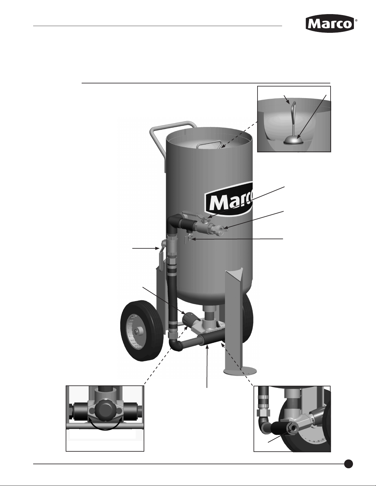
Operating Instructions (Figure 2)
Before using:
• Inspect Blast Machine for damage. Replace any damaged components before use.
• Inspect Filler Plug O-ring (2) and Filler Plug (1) for damage
• Test all Ball Valves (3, 8) for binding by turning to the fully open position and back to the
fully closed position. Replace immediately if damaged.
• Test Petcock (5) for binding by turning the handle 180 degrees (from the 9 o’clock to
3 o’clock position). Set Petcock (5) handle to a closed (9 or 3 o'clock )position.
• Test Bantam Metering Valve (6) by twisting Control Knob (7) one full turn clockwise then
counter-clockwise. Close Bantam Meter Valve by turning control knob clockwise until the
valve seats .
• Attach Blast Hose to Bantam Metering Valve (a).
• Attach KwikFire 153 to Blast Hose and install Blast Nozzle on KwikFire 153 (fig.7).
• Test KwikFire 153 Remote Control System by rotating Control Lever to the operating position
and release. If the Control Lever does not return to the closed postition, remove system from
service and inspect KwikFire 153 for damage before returning system to service.
• Fill Blast Machine with media.
• Attach Air Hose to 2-Lug Hose Fitting (4).
Ensure the surface is stable
and is sufficient to support the
weight of a Blast Machine full
of media. Unstable surfaces
and surfaces that cannot
support the gross weight of a
full blast machine could cause
the blast machine to tip over.
Failure to comply with the
above warning could result in
death or serious injury.
Never weld, grind or drill
on the blast machine (or any
pressure vessel). Doing so
will void ASME certification
and manufacturer’s warranty.
Welding, grinding or drilling
on the blast machine (or any
pressure vessel) could weaken
the vessel causing it to burst.
Failure to comply with the
above warning could result
in death or serious injury.
(ASME Pressure Vessel Code,
Section VIII, Division 1)
Inspect all equipment for
wear or damage before and
after each use. Failure to
use Original Equipment
Manufacturer repair parts and
failure to immediately replace
worn or damaged components
could void warranties and
cause malfunctions. Failure to
comply with the above warning
could result in death or serious
injury.
2.0 Cubic Foot L-Series Blast Machine
Never use the filler plug to lift
or move the blast machine.

2.0 CUBIC FOOT L-SERIES BLAST MACHINE
6
WWW.MARCOUSA.COM
2.0 Cubic Foot L-Series Blast Machine
Figure 2
2
1
a
Decrease
Media
Increase
Media
3
4
5
6
7
8

WWW.MARCOUSA.COM
7
2.0 CUBIC FOOT L-SERIES BLAST MACHINE
Operating Instructions (Figure 3)
To Start Blasting:
• Ensure Inlet Ball Valve (3) and Choke Valve (8) are in the closed position.
• Attach air hose to 2-Lug Air Hose Fitting (4).
• Grasp Filler Plug Handle (1) and pull up. Turn Inlet Ball Valve (3) to the open position. Wait for
the air from the compressor to pressurize the vessel.
• Release the Filler Plug Handle (1).
• Turn the Choke Valve (8) to the open position.
• To begin blasting, rotate Control Lever (a) on KwikFire 153 (6) to the full open operating
position .
• To stop media flow, release Control Lever (a) on KwikFire 153 (6).
• Adjust abrasive flow as needed to achieve maxium performance (see fig. 1).
To Stop Blasting Operation:
• To cease blasting release Control Lever (a) on KwikFire 153 (6).
• Close Bantam Metering Valve (7) by rotating Control Knob (b) clockwise until valve seats.
• Close Choke Valve (8).
• Close Inlet Valve (3).
• Turn Petcock (5) to the open (6 o’clock) position to release air from the Blast Machine.
• Once air cease to release from Petcock (5), move Filler Plug handle (1) back and forth to
release Filler Plug (2).
After Use:
• Empty media from Blast Machine when blasting is concluded for the day. To remove media
from Blast Machine :
Remove Kwikfire 153 assembly (6) from Blast Hose.
Turn Bantam Metering Valve (7) to a full open position.
Close Petcock (5) by rotating to the 3 o'clock or 9 o'clock position.
Securely hold Blast Hose, place hose end in a container suitable for catching the
media. Ensure Operator is prepared for strong recoil, the blast hose will provide
strong recoil as the media exits the blast hose.
Slowly open Inlet Valve (3).
After Blast Machine is empty of media, follow the procedure outlined in "To Stop
Blasting".
• Inspect Blast Machine components for damage. Replace damaged components before use.
• Cover Blast Machine when not in use to reduce debris and water intrusion.
Always be certain to have
secure footing when blasting.
There is a recoil hazard when
blasting starts that may cause
user to fall and misdirect the
abrasive stream at operator or
bystander. Failure to comply
with the above warning could
result in death or serious
injury.
Point the blast nozzle only
at the surface being blasted.
Never point the blast nozzle
or abrasive media stream at
yourself or others. Failure to
comply with the above warning
could result in death or serious
injury.
Crushing and pinching are
normal functions of this
component. Do not place body
parts or foreign objects in any
area where there are moving
parts. Failure to comply with
the above warning could result
in death or serious injury.
2.0 Cubic Foot L-Series Blast Machine
Never hang objects from
the blast machine handle.
Doing so may cause the blast
machine to become unstable
and tip over. Failure to comply
with the above warning could
result in death or serious
injury.

2.0 CUBIC FOOT L-SERIES BLAST MACHINE
8
WWW.MARCOUSA.COM
2.0 Cubic Foot L-Series Blast Machine
Figure 3
2
1
Decrease
Media
Increase
Media
3
4
5
7
b
8
closed
open
a
6

WWW.MARCOUSA.COM
9
2.0 CUBIC FOOT L-SERIES BLAST MACHINE
Troubleshooting
If the Blast Machine does not function properly, check the following:
SYMPTOM (Cause) ACTION
2.0 Cubic Foot L-Series Blast Machine
Insufficient air supply. Ensure air compressor
provides sufficient air volume to operate Blast
Machine and the Air Hose is of sufficient size to
provide adequate air volume.
Filler Plug or Filler Plug O-ring damaged. Inspect
Filler Plug and Filler Plug O-ring for wear or damage.
Replace damaged Filler Plug O-ring. If Filler Plug is
damaged remove blast machine from service.
Filler Plug not seated. Ensure Filler Plug is in proper
position and a proper seal has been achieved.
External Piping is damaged or loose. Inspect
external piping for damage. Confirm all fittings are
tight and free from damage.
With Blast Machine pressurized, close Choke Valve
to "Purge" and clear minor obstruction in Bantam
Metering Valve, Blast Hose or Nozzle.
Depressurize Blast Machine. Inspect Blast
Nozzle, optional KwikFire 153, and Blast Hose for
obstruction. Never look directly down the exit port
of the Blast Nozzle. Remove obstruction.
Damp or wet media. Remove all media from Blast
Machine and Metering Valve. Ensure dry media is
used.
Slightly open optional Moisture Separator Petcock
to allow collected moisture to escape while Blast
Machine is in use.
Consult Ceramic Nozzles Chart (Fig. 8) for compatible
media and nozzle selection.
Refer to Bantam Metering Valve and/or KwikFire 153
Operator's Manual for proper instructions.
Always depressurize the entire
blasting system, disconnect all
electrical power sources and
lockout/tagout all components
before any maintenance or
troubleshooting is attempted.
Failure to comply with the above
warning could cause electrical
shock and inadvertent activation
of equipment resulting in death
or serious injury.
Crushing and pinching are
normal functions of this
component. Do not place body
parts or foreign objects in any
area where there are moving
parts. Failure to comply with
the above caution may result in
minor or moderate injury.
Blast Machine will not pressurize
(Improper Air Supply, Damaged Components)
Neither air nor media exits the blast nozzle
(Obstructions, Wet Media, Metering Valve, Improperly
Sized Media, optional KwikFire 153)
Release of high speed media
and compressed air occurs
during depressurization of
the blast machine. Ensure
appropriate Personal Protective
Equipment is in use. Failure to
comply with the above caution
may result in minor or moderate
injury.
Moisture build-up occurs when
air is compressed. Any moisture
within the blast system will
cause media to clump, clogging
metering valves, hoses and
nozzles. Install an appropriately
sized moisture separator at
the inlet of the blast machine.
Leave the moisture separator
petcock slightly open to allow
for constant release of water. If
insufficient volume of air exists
and petcock is unable to be
left open (at all times) petcock
should be opened frequently to
release water.

2.0 CUBIC FOOT L-SERIES BLAST MACHINE
10
WWW.MARCOUSA.COM
Troubleshooting
If the Blast Machine does not function properly, check the following:
SYMPTOM (Cause) ACTION
2.0 Cubic Foot L-Series Blast Machine
With Blast Machine pressurized, close Choke Valve
to "Purge" and clear minor obstruction in Bantam
Metering Valve, Blast Hose or Nozzle.
Depressurize Blast Machine. Inspect Blast
Nozzle, optional KwikFire 153, and Blast Hose for
obstruction. Never look directly down the exit port
of the Blast Nozzle. Remove obstruction.
Damp or wet media. Remove all media from Blast
Machine and Metering Valve. Ensure dry media is
used.
Slightly open optional Moisture Separator Petcock
to allow collected moisture to escape while Blast
Machine is in use.
Consult Ceramic Nozzles Chart (Fig. 8) for compatible
media and nozzle selection.
Refer to Bantam Metering Valve and/or KwikFire 153
Operator's Manual for proper instructions.
Insufficient air supply. Ensure air compressor
provides sufficient air volume to operate Blast
Machine and the Air Hose is of sufficient size to
provide adequate air volume.
Filler Plug or Filler Plug O-ring damaged. Inspect
Filler Plug and Filler Plug O-ring for wear or damage.
Replace damaged Filler Plug O-ring. If Filler Plug is
damaged remove blast machine from service.
External Piping Damaged or Loose. Inspect external
piping for damage. Confirm all fittings are tight and
free from damage.
Damp or wet media. Remove all media from Blast
Machine and Metering Valve. Ensure dry media is
used.
Slightly open optional Moisture Separator Petcock
to allow collected moisture to escape while Blast
Machine is in use.
Consult Ceramic Nozzles Chart (Fig. 8) for compatible
media and nozzle selection.
Refer to Bantam Metering Valve and/or KwikFire 153
Operator's Manual for proper instructions.
Only air exits Blast Nozzle
(Obstructions, Wet Media, Metering Valve,
Improperly Sized Media)
Inconsistent media flow
(Improper Air Supply, Damaged Components,
Wet Media, Improperly Sized Media)
Always depressurize the entire
blasting system, disconnect all
electrical power sources and
lockout/tagout all components
before any maintenance or
troubleshooting is attempted.
Failure to comply with the above
warning could cause electrical
shock and inadvertent activation
of equipment resulting in death
or serious injury.
Crushing and pinching are
normal functions of this
component. Do not place body
parts or foreign objects in any
area where there are moving
parts. Failure to comply with
the above caution may result in
minor or moderate injury.
Release of high speed media
and compressed air occurs
during depressurization of
the blast machine. Ensure
appropriate Personal Protective
Equipment is in use. Failure to
comply with the above caution
may result in minor or moderate
injury.
Moisture build-up occurs when
air is compressed. Any moisture
within the blast system will
cause media to clump, clogging
metering valves, hoses and
nozzles. Install an appropriately
sized moisture separator at
the inlet of the blast machine.
Leave the moisture separator
petcock slightly open to allow
for constant release of water. If
insufficient volume of air exists
and petcock is unable to be
left open (at all times) petcock
should be opened frequently to
release water.

WWW.MARCOUSA.COM
2.0 CUBIC FOOT L-SERIES BLAST MACHINE
Maintenance
Maintenance of the Blast Machine is limited to the daily cleaning and the immediate replacement of
damaged or worn parts.
2.0 Cubic Foot Industrial Blast Machine
Filler Plug O-ring: (Figure 4)
Disassembly:
1) Lift Filler Plug (1) close to Filler Plug Opening (a), leaning to one side for access to Filler Plug
O-Ring (2).
2) Pull Filler Plug O-Ring (2) from recessed area on Filler Plug (1).
3) Pull Filler Plug O-Ring (2) over Filler Plug (1) handle one side at a time.
Assembly:
1) Slip Filler Plug O-ring (2) over Filler Plug (1) handle one side at a time, taking care to not over stretch
or otherwise damage Filler Plug O-ring (2).
2) Lift Filler Plug (1) close to the opening, leaning to one side to access recessed area that receives the
Filler Plug O-Ring (2).
3) Starting on exposed face, roll Filler Plug O-ring (2) into recessed area on Filler Plug (1), rotating Filler
Plug handle until Filler Plug O-ring (2) is completely seated.
4) Pull Filler Plug (1) in to place to test Filler Plug O-ring (2) seating.
Nozzle Assembly and KwikFire 153 Installation: (Fig.4)
Disassembly:
1) Unthread Nozzle Cap (11) from KwikFire 153 (8).
2) Remove Nozzle (10) from KwikFire 153 (8).
3) Remove Nozzle Washer (9) from KwikFire 153 (8).
4) Remove KwikFire 153 (8) from Nozzle Holder Base (6).
5) Remove Liner (7) from Nozzle Holder Base (6).
6) Remove Nozzle Holder Base (6) from Blast Hose Assembly (5).
Assembly:
1) Attach Nozzle Holder Base (6) to Blast Hose Assembly (5).
2) Insert Liner (7) into Nozzle Holder Base (6).
3) Attach KwikFire 153 (8) to Nozzle Holder Base (6).
4) Insert Nozzle Washer (9) into KwikFire 153 (8).
5) Insert Nozzle (10) into KwikFire 153 (8).
6) Attach Nozzle Cap (11) onto KwikFire 153 (8).
Hose End Assembly: (Fig. 4)
Disassembly:
1) Remove Nozzle Assembly and Kwikfire 153 (6-11) from Hose End Assembly (5).
2) Remove Hose Clamp (4) from Blast Hose (5).
3) Remove Blast Hose End (3) from Blast Hose (5).
Assembly:
1) Cut the Blast Hose (5) square, leaving a smooth and even end.
2) Wet barb of Blast Hose End (3) with a small amount of liquid detergent.
3) Insert Blast Hose End (3) into Blast Hose (5).
4) Place Hose Clamp (4) 1/4" from end of Blast Hose (5) and tighten.
5) Attach Nozzle Assembly and Kwikfire 153 (6-11) to Hose End Assembly (5).
2.0 Cubic Foot L-Series Blast Machine
11
Always depressurize the entire
blasting system, disconnect all
electrical power sources and
lockout/tagout all components
before any maintenance or
troubleshooting is attempted.
Failure to comply with the
above warning could cause
electrical shock and
inadvertent activation of
equipment resulting in death
or serious injury.
Piping may loosen during
transit. Ensure all piping is
aligned and tightened before
use.
Never weld, grind or drill
on the blast machine (or any
pressure vessel). Doing so
will void ASME certification
and manufacturer’s warranty.
Welding, grinding or drilling
on the blast machine (or any
pressure vessel) could weaken
the vessel causing it to burst.
Failure to comply with the
above warning could result
in death or serious injury.
(ASME Pressure Vessel Code,
Section VIII, Division 1)
Apply pipe thread sealant to
all pipe threads to ensure an
airtight seal.

2.0 CUBIC FOOT L-SERIES BLAST MACHINE
12
WWW.MARCOUSA.COM
2.0 Cubic Foot L-Series Blast Machine
Figure 4
2
1
a
53
4
6
7
8
9
11 10

WWW.MARCOUSA.COM
13
2.0 CUBIC FOOT L-SERIES BLAST MACHINE
2.0 Cubic Foot L-Series Blast Machine Schematic
Figure 5
Item # Part # Description
Fig. 5 1002001 2.0 Cubic Foot L-Series Blast Machine with 25 feet of 1/2” i.d. Blast Hose
with Fittings installed and KwikFire 153 Remote Control Handle
1002001PKB 2.0 Cubic Foot L-Series Blast Machine with Extractor Junior Moisture Separator,
25 feet of 1/2” i.d. Blast Hose with Fittings and KwikFire 153 Remote Control Handle
1 10L650R Filler Plug O-Ring
2 1011601 1” Full Port Brass Ball Valve (2 required)
3 10ME2 2-lug Air Hose Coupling - 1” NPT Male Threads
4 1012151 1” NPT Close Nipple (5 required)
5 1012101 1/4” NPT Petcock
6 1011813 1-1/4” NPT x 2” Pipe Nipple
7 1011812 1” NPT (Male) x 1/2” (Female) Bushing
8 1014103 Bantam Metering Valve with 1” (F) x 1” (F) Nipple
9 1011815 1” NPT x 5” long Pipe Nipple
10 1011801 1” 90 Degree Street Elbow
11 1006066 10 X 2.75 Solid Wheel (2 required)
12 1011807 5/8” E-Clip (4 required)
13 1006308 1” NPT Air Hose Pusher Line Assembly
14 1011808 1” NPT Pipe Elbow with Side-out
15 1011814 1” x 1” x 1/4” NPT Pipe Tee
16 10L66EVD KwikFire 153 Remote Control Handle
17 1011750 Extractor Junior Moisture Separator (optional)
- 1002101 14” Cover for 2.0 Industrial Series Blast Machine (optional)
- 1002102 14” Recessed Screen for 2.0 Industrial series Blast Machine (optional)
- 1091045 Hazard Identification Tag
- 1090050 2.0 Cubic Foot Industrial Series Blast Machine Operator’s Manual
- 1090034 KwikFire 153 Operator's Manual

2.0 Cubic Foot L-Series Blast Machine Schematic
2.0 CUBIC FOOT L-SERIES BLAST MACHINE
14
WWW.MARCOUSA.COM
Figure 5 1
2
3
4
6
8
2
5
10 9
7
11
16
13
4
4
14
15
4
17 (optional)
12

WWW.MARCOUSA.COM
15
2.0 CUBIC FOOT L-SERIES BLAST MACHINE
1/2" Hose End Assembly
Figure. 6
1
2
3
4
5
6
723
Item # Part # Description
1a 10L850119 10' of 1/2” ID/1-3/16" OD Blast Hose with 2 each of items 2 & 3 installed
1b 10L850120 25' of 1/2” ID/1-3/16" OD Blast Hose with 2 each of items 2 & 3 installed
1c 10L850125 50' of 1/2” ID/1-3/16" OD Blast Hose with 2 each of items 2 & 3 installed
1d 10BH01210C 1/2” ID/1-3/16" Blast Hose - 10'
1e 10BH012125C 1/2” ID/1-3/16" Blast Hose - 12.5'
1f 10BH01225C 1/2” ID/1-3/16" Blast Hose - 25'
1g 10BH012C 1/2” ID/1-3/16" Blast Hose - 50'
2 10L800034 Hose Clamp for 1/2” ID Hose (2 Required)
3 10L174 1/2” I.D. Blast Hose End with 1/2” NPT threads (2 Required)
4 10L66B Nozzle Holder Base (Type 1)
5 10L66CHW Rubber Washer for Type 1 Nozzle
6 Type 1 Nozzle (See Fig. 8 for size options)
7 10L100164 Nozzle Cap (Fits 10L366HE, 10L466HE and 10L66B)
KwikFire 153 Assembly
Figure. 7
1
3
4
5
6
7
Item # Part # Description
1 - Blast Hose (See Fig. 6 for length options)
2 10L66B Nozzle Holder Base (Type 1)
3 10L800236 Rubber Liner
4 10L66EVD KwikFire 153 Remote control Handle - Complete
5 10L66CHW Rubber Washer for Type 1 Nozzle
6 Type 1 Nozzle (See Fig. 8 for size options)
7 10L100164 Nozzle Cap (Fits 10L366HE, 10L466HE and 10L66B)
2

2.0 CUBIC FOOT L-SERIES BLAST MACHINE
16
WWW.MARCOUSA.COM
Maintenance Notes
DATE TYPE OF SERVICE PART NUMBER
Ceramic Blast Nozzles
Figure. 8
Part # Size Orifice CFM @ 100 PSI Media Size (Mesh) Blast Hose Internal Size
10CN051 1 3/32" 10 100 Mesh or finer 1/2"
10CN251 2 1/8" 20 60 Mesh or finer 1/2"
10CN21251 2-1/2 5/32" 33 50 Mesh or finer 1/2"
10CN351 3 3/16" 45 50 Mesh or finer 3/4"
10CN451 4 1/4" 81 40 Mesh or finer 3/4"
10CN551 5 5/16" 137 20 Mesh or finer 1"
10CN651 6 3/8" 196 12 Mesh or finer 1"

17
WWW.MARCOUSA.COM
2.0 CUBIC FOOT L-SERIES BLAST MACHINE
2.0 Cubic Foot L-Series Blast Machine
Maintenance Notes
DATE TYPE OF SERVICE PART NUMBER

2.0 CUBIC FOOT L-SERIES BLAST MACHINE
18
WWW.MARCOUSA.COM
ADDITIONAL
TECHNICAL DATA
The associations listed
below offer information,
materials and videos
pertaining to media
blasting and safe
operating practices.
• American Society
for Testing and
Materials (ASTM)
100 Barr Harbor Drive
West Conshohockon,
PA 19428-2959
Phone: (610) 832-9585
FAX: (610) 832-9555
www.astm.org
• Occupational
Safety & Health
Administration (OSHA)
United States
Department of Labor
200 Constitution Avenue
Washington, DC 20210
Phone: (800) 321-OSHA
(800) 321-6742
www.osha.gov
• The National Board
of Boiler & Pressure
Vessel Inspectors
1055 Crupper Avenue
Columbus, Ohio 43229
Phone: (614) 888-8320
FAX: (614) 888-0750
www.nationalboard.org
•National Association
of Corrosion Engineers
(NACE)
1440 South Creek Drive
Houston, TX 77084-4906
Phone: (281) 228-6200
FAX: (281) 228-6300
www.nace.org
• The Society
for Protective
Coatings (SSPC)
40-24th Street, 6th Floor
Pittsburgh, PA 15222-4656
Phone: (412) 281-2331
FAX: (412) 281-9992
www.sspc.org
WARRANTY
Seller warrants to the original purchaser that the Product covered by this Warranty will remain free from defects in
workmanship or material under normal commercial use and service for a period of one year from the date of shipment
to the original Purchaser. This Warranty shall not apply to defects arising, in whole or in part, from any accident,
negligence, alteration, misuse or abuse of the Product, operation not in accordance with applicable instructions or
manuals or under conditions more severe than, or otherwise exceeding, those set forth in the written specifications
for the Product, nor shall this Warranty extend to repairs or alterations of the Product by persons other than Seller or
Seller’s authorized representatives, or to maintenance parts.
DISCLAIMER OF WARRANTY
The foregoing Warranty is exclusive and is in lieu of all other warranties of quality, whether oral or written and whether
express or implied. All warranties of merchantability or fitness for a particular purpose are hereby excluded and are
inapplicable to the Product. Seller makes no warranties or representations concerning respirators, or equipment made
by other manufacturers.
EXCLUSIVE REMEDIES FOR WARRANTY CLAIMS
THE SOLE AND EXCLUSIVE REMEDIES OF PURCHASER FOR UNDER THE FOREGOING WARRANTY COVERING THIS
PRODUCT SHALL BE REPAIR OR REPLACEMENT, FREE OF CHARGE, F.O.B. POINT OF MANUFACTURE, OF ANY DEFECTIVE
PART OR PARTS OF THE PRODUCT THAT WERE MANUFACTURED BY SELLER, AND WHICH ARE RETURNED TO SELLER AT
SELLER’S PRINCIPAL PLACE OF BUSINESS, POSTAGE PREPAID. THIS SOLE AND EXCLUSIVE REMEDY IS CONDITIONED
UPON PURCHASER’S PROMPT WRITTEN NOTICE TO SELLER AT SELLER’S PLACE OF BUSINESS THAT A DEFECT HAS BEEN
DISCOVERED, TOGETHER WITH A REASONABLY DETAILED DESCRIPTION OF THE DEFECT IN THE PRODUCT, WITHIN THIRTY
(30) DAYS AFTER DISCOVERY OF THE DEFECT, OTHERWISE SUCH CLAIMS SHALL BE DEEMED WAIVED. NO ALLOWANCE
WILL BE GRANTED FOR ANY REPAIRS OR ALTERATIONS MADE BY PURCHASER OR OTHERS WITHOUT SELLERS PRIOR
WRITTEN CONSENT. IF SUCH NOTICE IS TIMELY GIVEN, SELLER WILL HAVE THE OPTION TO EITHER MODIFY THE PRODUCT
OR COMPONENT PART THEREOF TO CORRECT THE DEFECT, REPLACE THE PRODUCT OR PART WITH COMPLYING PRODUCTS
OR PARTS, OR REFUND THE AMOUNT PAID FOR THE DEFECTIVE PRODUCT, ANY ONE OF WHICH WILL CONSTITUTE THE
SOLE LIABILITY OF SELLER AND FULL SETTLEMENT OF ALL CLAIMS. PURCHASER SHALL AFFORD SELLER PROMPT AND
REASONABLE OPPORTUNITY TO INSPECT THE PRODUCT FOR WHICH CLAIM IS MADE. THE SOLE PURPOSE OF THE
FOREGOING STIPULATED EXCLUSIVE REMEDY SHALL BE TO REPAIR OR REPLACE DEFECTIVE PRODUCTS OR COMPONENTS
THEREOF, OR TO REFUND PURCHASER THE PURCHASE PRICE THEREOF. THIS STIPULATED EXCLUSIVE REMEDY SHALL
NOT BE DEEMED TO HAVE FAILED OF ITS ESSENTIAL PURPOSE SO LONG AS SELLER IS WILLING AND ABLE TO REPAIR OR
REPLACE THE DEFECTIVE PARTS OR REFUND THE PURCHASE PRICE IN ACCORDANCE WITH THE TERMS HEREOF.
LIMITATION OF REMEDIES
The foregoing stipulated exclusive remedies is in lieu of all other remedies for breach of contract, warranty and/or tort.
Seller shall not be liable for the Purchaser's expenses for downtime or for making up downtime, damages for which the
Purchaser may be liable to other persons and/or entities, damages to property, and injury to or death of any persons
and/or any claims for incidental or consequential damages, including but not limited to loss of profits, regardless
of whether Seller has been informed of the possibility of such damages. Seller neither assumes nor authorizes any
person to assume for it any other liability in connection with the sale or use of any Products covered by the foregoing
Warranty and Disclaimers, and there are no oral agreements relating to remedies which are collateral to or which affect
this limitation.

DAILY
PRE-OPERATION
CHECKLIST
blast machine lid
blast machine screen
air hose
abrasive trap
remote control system
exhaust muffler
air hose couplings & gaskets
moisture separator
metering valve
whip check cable
blast hose couplings & gaskets
remote control line
remote control handle
blasting nozzle holder
blasting nozzle
blasting gloves
media resistant blastsuit
breathing line
climate control device
Additional Components
MEDIAS:
• Review the Media MSDS
(Material Safety Data Sheet)
to ensure the material is free of
toxic or harmful substances such
as lead, silica, cyanide or
arsenic. Use properly sized
media to ensure required
surface finish.
BLAST MACHINE:
• Inspect the Blast Machine
for internal and external wear,
abrasions and leaks.
• Ground the Blast Machine
to dissipate static electricity
created by the Media moving
through the Blast Hose.
• Install a Moisture Separator
at the Inlet Port of the Blast
Machine. Removing moisture
from the Air Supply will allow
Media to flow smoothly from
the Blast Machine to the
work surface.
• Inspect abrasive trap filter and
empty trap frequently
• Inspect exhaust muffler and filter
element before starting blasting
operations. Replace filter
element if exhaust air flow is
restricted by residule dust
AIR SUPPLY: Respirator
• Inspect Respirator Assemblies
for worn components and
replace as needed.
• You MUST consult the
Operator’s Manual supplied
with your Respirator for ALL
applicable Warnings and
Hazards.
BLAST NOZZLES:
• Replace Blast Nozzles if liner
or jacket is cracked, damaged or
an orifice size 1/16” larger than
the original size.
– Determine Nozzle wear by
inserting a drill bit 1/16
”
larger than original size of the
Nozzle orifice. If the drill bit
passes, replacement is needed.
•Blast Nozzles with ½” I.D. or
1” I.D. Entry require use of a
Nozzle Washer. Wide Entry
(1-1/4” I.D.) Blast nozzles do not
require a Nozzle Washer.
Inspect and replace damaged
Nozzle Holder or Nozzle Washer
before use.
AIR SUPPLY: Blast Machine
• Use an Air Compressor that
will provide sufficient CFM
(Cubic Feet Per Minute)
volume
of air to the Blast Nozzle and all
other pneumatic tools, with an
additional 50% to allow for
Nozzle wear.
AIR & BLAST HOSE:
• Inspect all Hoses for internal
and external wear, abrasions
and leaks.
• Lay out Air Hose and Blast
Hose as straight as possible to
remove restrictions which cause
reduced performance and
premature wear.
• Blast Hose I.D. should be 3-4
times the size of Nozzle orifice.
• Blast Hose and Air Hose
Couplings are to mate securely
using Gaskets to provide a
positive seal without leaks.
Inspect and replace any worn or
damaged component before use.
• Install Safety Clips and Safety
Cables at each connection.
PROTECTIVE CLOTHING:
• Wear appropriate Protective
Clothing and Equipment
(supplied-air respirator,
blastsuit, safety shoes,
leather gloves, ear protection
and eye protection)
appropriate
for the work environment.
Marco • 3425 East Locust Street • Davenport, Iowa 52803 • Certified ISO 9001:2000
Phone: (800) 252-7848
Fax: (563) 324-6258
e-mail: sales@marcousa.com
www.marcousa.com
Supplied Air
Respirator
Free Air Pump*
Supplied Air
Respirator
Carbon Monoxide
Monitor
Breathing
Air Filter
1
2
3
3
4
5
6
7
8
9
12
10
11
13
14
15
16
17
18
19
Air Compressor*
Air Compressor*
16
17
19
Abrasives
1
2
3
4
5
6
7
8
9
10
19
12
13
14
11
18
17
16
15
This manual suits for next models
1
Table of contents
Other Marco Industrial Equipment manuals