manuals.online logo
Brands
  1. Home
  2. •
  3. Brands
  4. •
  5. Siemens
  6. •
  7. Industrial Equipment
  8. •
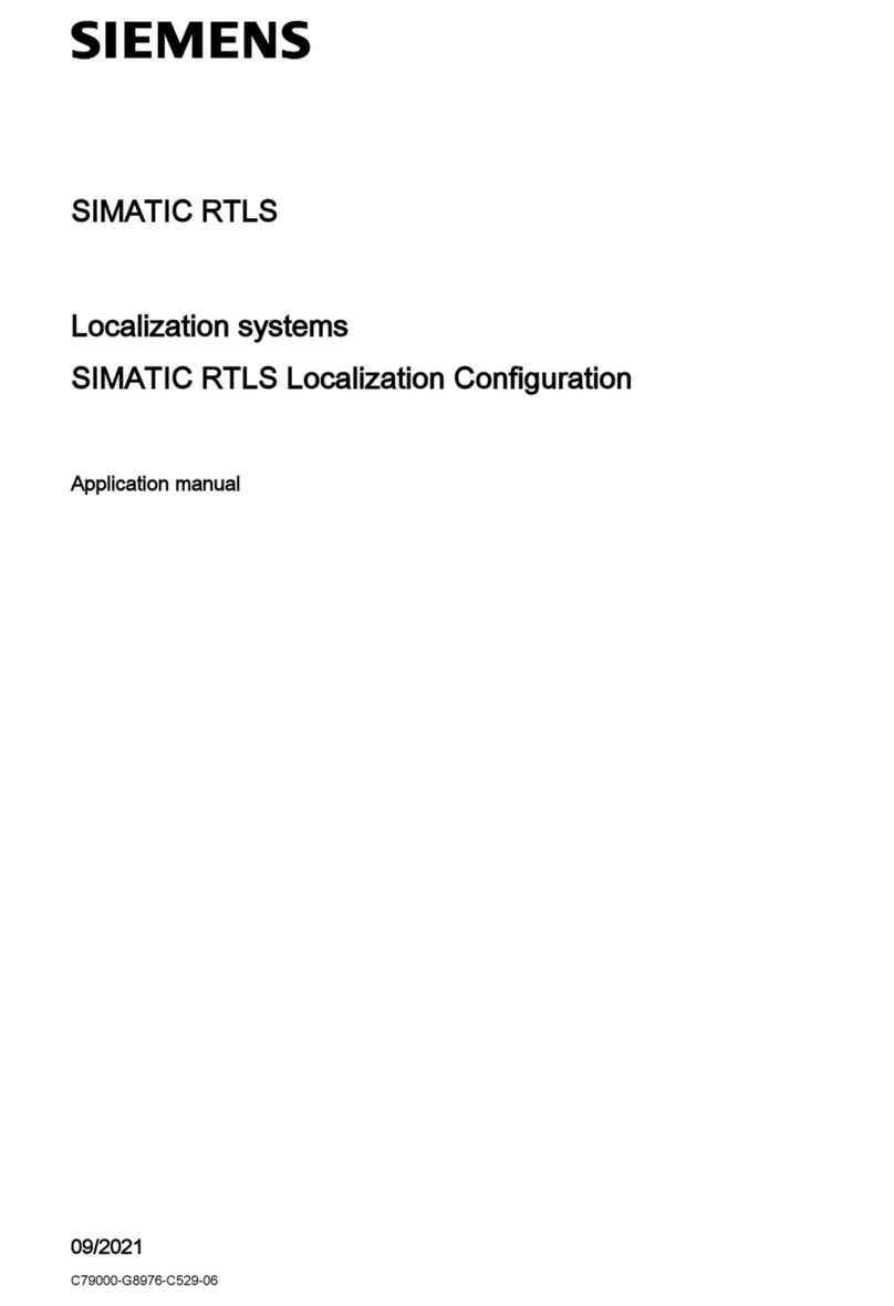
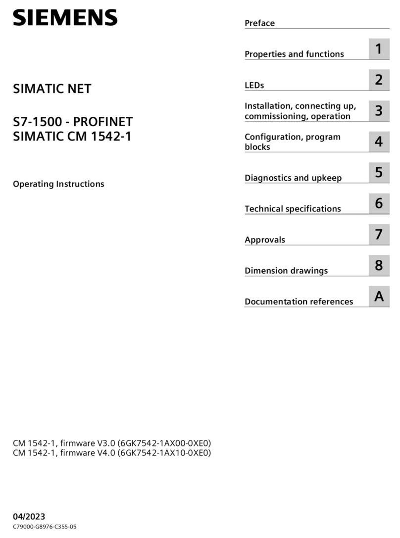
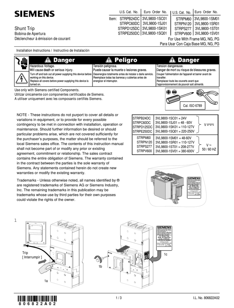
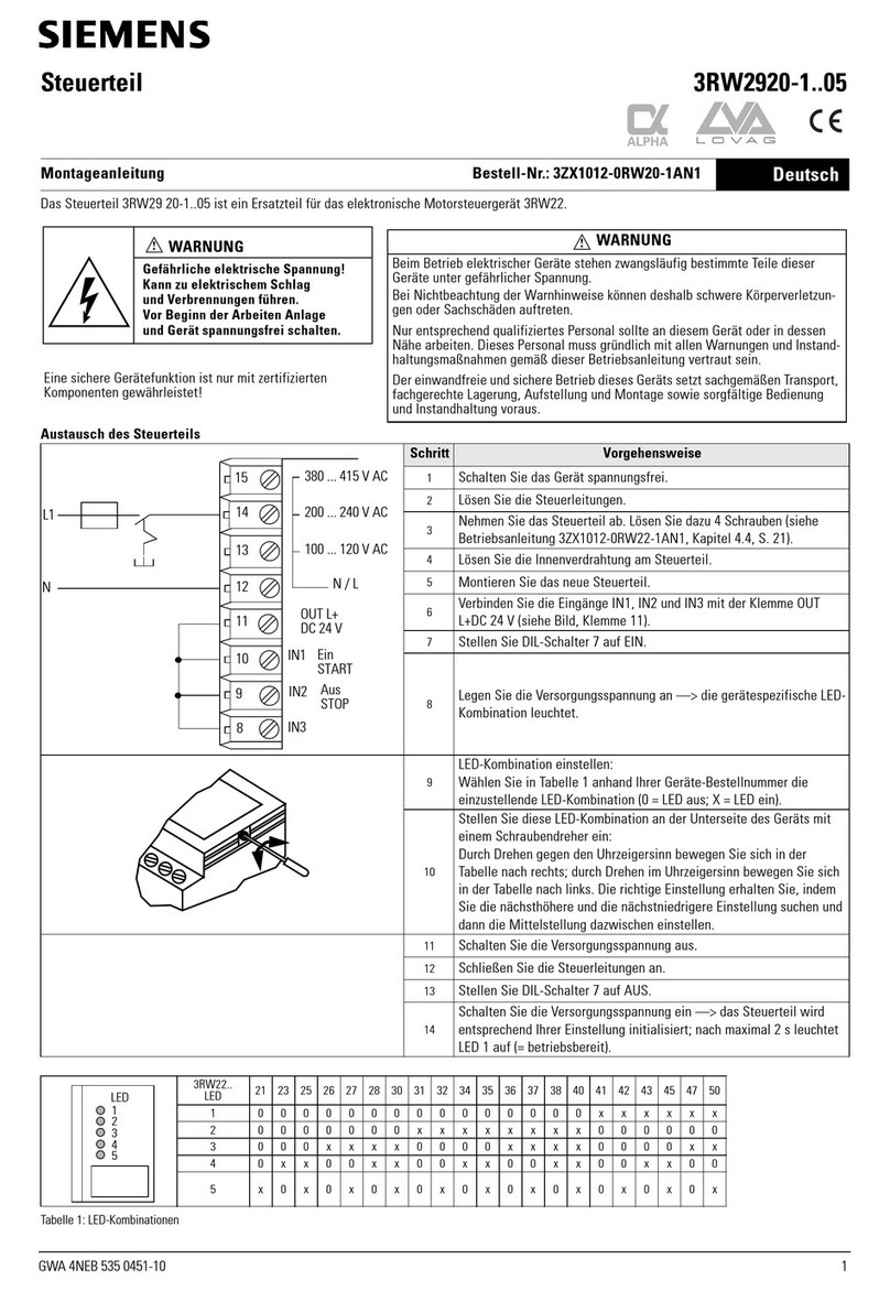
  9. Siemens SIMATIC HMI ITC1200 V3 PRO User manual

Siemens SIMATIC HMI ITC1200 V3 PRO User manual

1.1 Wichtige Hinweise – Important information
Allgemeine Sicherheitshinweise – General safety instructions
Betriebsanleitung – Operating Instructions
Bediengerät einbauen
Mounting the HMI device
1
Dieses Dokument ist lediglich eine Montageanleitung. Sicherheitshinweise, sowie die vollständige
Montage und Inbetriebnahme sind in der Betriebsanleitung beschrieben.
This document provides simple installation instructions. Complete installation, commisioning
and safety instructions are described in the Operating Instructions.
https://support.industry.siemens.com/cs/ww/en/view/109801145
SIMATIC HMI
Quick Install Guide
ITC1200 V3 PRO
ITC1500 V3 PRO
ITC1900 V3 PRO
ITC2200 V3 PRO
ITC2400 V3 PRO
Bediengerät einbauen
Mounting the HMI device
Bediengerät anschließen
Connecting the HMI device
Gerät in Betrieb nehmen
Commissioning the device
Reparatur und Ersatzteile Service and spare parts
https://support.industry.siemens.com/sc/de/en/sc
Technische Support-Zentrale – Central Technical Support
https://support.industry.siemens.com
05/2023
A5E42761137-AE
45 °C
0 °C
40 °C
0 °C
40 °C
0 °C
0°- 35°
0°- 35°
40 °C
0 °C
40 °C
0 °C
0 °C
45 °C
0°- 35°
0°- 35°
2
1
2
1
VESA-System/
VESA system
Drittanbieter-System/
3rd party system
4 screws M6x12
Torque: refer to support arm
documentation
4 Schrauben M6x12
Drehmoment: siehe
Tragarm-Dokumentation
2
1
2
1
VESA-System/
VESA system
Drittanbieter-System/
3rd party system
4 screws M6x12
Torque: refer to support arm
documentation
4 Schrauben M6x12
Drehmoment: siehe
Tragarm-Dokumentation
5
6
4 Schrauben/screws M4x12
PRO-Geräte für Standfuß (erweiterbar, Flansch unten)
PRO devices for pedestal (extendable, flange bottom)
PRO-Geräte für Tragarm (nicht erweiterbar, Flansch oben)
PRO devices for support arm (not extendable, flange top)
4 Schrauben/screws M4x12
5
6
1.2 Zulässige Einbaulagen – Valid Mounting positions
1.3 Bediengerät anbauen – Mounting the HMI device
3
TX 20
4
TX 20
0.8 Nm
für Standfuß (erweiterbar, Flansch unten) und
für Tragarm (nicht erweiterbar, Flansch oben)
for pedestal (extendable, flange bottom) and
for support arm (not extendable, flange top)
3
TX 20
4
TX 20
0.8 Nm
4
TX 20
2.5 Nm
4
TX 20
2.5 Nm
C
M
Y
CM
MY
CY
CMY
K
hmi_itc_v3_pro_quick_install_guide_page_1.eps 1 16.05.2023 17:37:52hmi_itc_v3_pro_quick_install_guide_page_1.eps 1 16.05.2023 17:37:52
Bediengerät anschließen
Connecting the HMI device
Leitungen sichern – Securing cables
Potenzialausgleich – Equipotential bonding
Route equipotential bonding
conductors and data cables in
parallel with minimum clearance.
Do not use conductor shields for
equipotential bonding.
CAUTION
!
Verlegen Sie Potenzialausgleichs-
und Datenleitungen parallel mit
minimalem Abstand.
Verwenden Sie Leitungsschirme
nicht zum Potenzialausgleich.
VORSICHT
!
Stromversorgung anschließen – Connecting the power supply
Only 24 VDC!
CAUTION
!
Nur DC 24 V!
VORSICHT
!
3.1 Server anschließen – Connecting a server
3.2 Erstinbetriebnahme – Initial commissioning
Server
ITC
2
1
0/OFF
2.3
Anschlussfach schließen – Closing the connection compartment
2.4
2
Bediengerät in Betrieb nehmen
Commissioning the HMI device
3
Weitere Informationen finden Sie in der Betriebsanleitung.
You will find additional information in the operating instructions.
https://support.industry.siemens.com/cs/ww/en/view/109801145
Zugriff als Sm@rtClient auf ein HMI-Bediengerät über die WinCC-Option Sm@rtServer.
Zugriff als Web-Client auf einen Webserver z. B. einer S7-Steuerung oder das Intranet.
Zugriff als Client über das Protokoll "VNC" (Windows-Programme).
Zugriff als Citrix-Client auf einen Citrix-Server.
Zugriff als Client auf einen WinCC OA Server.
3.4 ITC mode | Weitere Einsatzmöglichkeiten – Additional possible applications
3.3 Auf Werkseinstellungen zurücksetzen – Restoring factory settings
2.2
2.1
After connecting the cables,
secure the cables with cable ties
on the marked fastening elements.
Sichern Sie die Leitungen nach
dem Anschließen über
Kabelbinder an den markierten
Befestigungselementen.
Typische Anwendungsfälle finden Sie in der Betriebsanleitung.
For typical applications, refer to the operating instructions.
https://support.industry.siemens.com/cs/ww/en/view/109801145
PROFINET/LAN
SINUMERIK mode
1
ON
2
ITC mode
3
ON
1
0/OFF
2
ITC ausschalten, Taster „B1“ drücken, ITC
einschalten und „B1“ gedrückt halten, bis der
Erstinbetriebnahmedialog angezeigt wird.
Turn ITC off, press the „B1“ button, turn ITC
on and hold „B1“ until the first commissioning
dialog is displayed.
3
Set administrator password
1
OK
2
Set device name
3
Next
4
Next
6
Set network properties
5
Save & Exit
8
Set connection properties
7
Server screen
SINUMERIK-Inbetriebnahme beendet
SINUMERIK commissioning finished
ITC Setup-Assistent
ITC setup wizard
Setup-Assistent, Beispiel: RDP-Verbindung einrichten
Setup wizard, example: Configuring an RDP connection
Server screen
ITC-Inbetriebnahme beendet
ITC commissioning finished
Access as a Citrix client to a Citrix server.
Access as a Client to a WinCC OA server.
Access to an HMI device as a Sm@rtClient via the WinCC Sm@rtServer option.
Access as a web client to a web server, e.g. of an S7 controller or the Intranet.
Access as a client via the "VNC" protocol (Windows programs).
16 mm²
PROFINET
1
4 mm²
3
2
TX 20
1.5 Nm
DC 24 V
I
0
ML+
1
0/OFF
PRO-Geräte für Standfuß (erweiterbar, Flansch unten)
PRO devices for pedestal (extendable, flange bottom)
PRO-Geräte für Tragarm (nicht erweiterbar, Flansch oben)
PRO devices for support arm (not extendable, flange top)
PRO-Geräte für Standfuß (erweiterbar, Flansch unten)
PRO devices for pedestal (extendable, flange bottom)
PRO-Geräte für Tragarm (nicht erweiterbar, Flansch oben)
PRO devices for support arm (not extendable, flange top)
For the 24 V DC supply, use only power
supply units with safe electrical isolation
(SELV/PELV) in accordance with
IEC 61010-2-201 or IEC 62368-1.
NOTICE
!
Verwenden Sie für die DC-24-V-
Versorgung nur Netzgeräte mit sicherer
elektrischer Trennung (SELV/PELV) nach
IEC 61010-2-201 oder IEC 62368-1.
ACHTUNG
!
2
0.5 ... 1.5 mm²
3
3 ... 3.5 mm
1.5 Nm
Beispiel
Example
Befestigen Sie den Anschlussfachdeckel mit seinen 2 Schrauben am Gerät, Drehmoment 1,5 Nm.
Beachten Sie den korrekten Sitz der Dichtung.
Fasten the terminal compartment
cover to the device with its 2
screws, torque 1.5 Nm. Check
that the seal is sitting correctly.
2
TX 20
1.5 Nm
TX 20
1.5 Nm
B1
4
4
C
M
Y
CM
MY
CY
CMY
K
hmi_itc_v3_pro_quick_install_guide_page_2.eps 1 16.05.2023 17:38:12hmi_itc_v3_pro_quick_install_guide_page_2.eps 1 16.05.2023 17:38:12
This manual suits for next models

4

Other Siemens Industrial Equipment manuals

Siemens SIRIUS 3RT292 5A Series User manual

Siemens

Siemens SIRIUS 3RT292 5A Series User manual

Siemens SENTRON VL 160 User manual

Siemens

Siemens SENTRON VL 160 User manual

Siemens MOBILETT Plus Operating instructions

Siemens

Siemens MOBILETT Plus Operating instructions

Siemens SICAM A8000 Series User manual

Siemens

Siemens SICAM A8000 Series User manual

Siemens SINUMERIK ONE NCU 1740 Technical Document

Siemens

Siemens SINUMERIK ONE NCU 1740 Technical Document

Siemens 3VA9978 - 0AB1 Series User manual

Siemens

Siemens 3VA9978 - 0AB1 Series User manual

Siemens SIREMOBIL Iso-C 3D Installation manual

Siemens

Siemens SIREMOBIL Iso-C 3D Installation manual

Siemens 3VA915 0JA11 Series User manual

Siemens

Siemens 3VA915 0JA11 Series User manual

Siemens LITHOSTAR Multiline User manual

Siemens

Siemens LITHOSTAR Multiline User manual

Siemens SIMATIC NET SCALANCE M-800 User manual

Siemens

Siemens SIMATIC NET SCALANCE M-800 User manual

Siemens 8MF1 Series User manual

Siemens

Siemens 8MF1 Series User manual

Siemens SIRIUS S00 User manual

Siemens

Siemens SIRIUS S00 User manual

Siemens SIWAREX WL270 CP-S SA User manual

Siemens

Siemens SIWAREX WL270 CP-S SA User manual

Siemens SIMATIC User manual

Siemens

Siemens SIMATIC User manual

Siemens SINAMICS G130 Parts list manual

Siemens

Siemens SINAMICS G130 Parts list manual

Siemens SINAMICS S120 Technical Document

Siemens

Siemens SINAMICS S120 Technical Document

Siemens FCM2018-U3 Series Guide

Siemens

Siemens FCM2018-U3 Series Guide

Siemens SIREMOBIL Compact L User instructions

Siemens

Siemens SIREMOBIL Compact L User instructions

Siemens SCALANCE Setup guide

Siemens

Siemens SCALANCE Setup guide

Siemens 8UD1 1 A Series User manual

Siemens

Siemens 8UD1 1 A Series User manual

Siemens SIRIUS 3RW30 User manual

Siemens

Siemens SIRIUS 3RW30 User manual

Siemens Flender H2NV Series User manual

Siemens

Siemens Flender H2NV Series User manual

Siemens SIVACON S4 User manual

Siemens

Siemens SIVACON S4 User manual

Siemens FS4 User manual

Siemens

Siemens FS4 User manual

Popular Industrial Equipment manuals by other brands

schmersal EX-BNS 250 operating instructions

schmersal

schmersal EX-BNS 250 operating instructions

WIRTGEN HAMM H195 Series operating manual

WIRTGEN

WIRTGEN HAMM H195 Series operating manual

STABILUS ACE TUBUS TR-HD Operating and mounting instructions

STABILUS

STABILUS ACE TUBUS TR-HD Operating and mounting instructions

ABB Relion REB500 Communication protocol manual

ABB

ABB Relion REB500 Communication protocol manual

PairGain UTU-722 Quick installation guide

PairGain

PairGain UTU-722 Quick installation guide

ebatec GS 81 operating instructions

ebatec

ebatec GS 81 operating instructions

Enduro EM304 user manual

Enduro

Enduro EM304 user manual

Finn-Power FP20 IS/AS operating instructions

Finn-Power

Finn-Power FP20 IS/AS operating instructions

ABB TPL-B Series Assembly instructions

ABB

ABB TPL-B Series Assembly instructions

PI A-62 Series user manual

PI

PI A-62 Series user manual

OZCO 56621 installation instructions

OZCO

OZCO 56621 installation instructions

Pfannenberg PWS 7 Series Operating and installation instructions

Pfannenberg

Pfannenberg PWS 7 Series Operating and installation instructions

Baileigh Industrial BB-12010H Operator's manual

Baileigh Industrial

Baileigh Industrial BB-12010H Operator's manual

Chore-Time Linear Lift 50558 Series manual

Chore-Time

Chore-Time Linear Lift 50558 Series manual

STABILUS ACE MC33-V4A Operating and mounting instructions

STABILUS

STABILUS ACE MC33-V4A Operating and mounting instructions

Cascade Sciences MAXTRAP 50 Supplemental Installation & Operation Manual

Cascade Sciences

Cascade Sciences MAXTRAP 50 Supplemental Installation & Operation Manual

Aventics DDL-X-Tool operating instructions

Aventics

Aventics DDL-X-Tool operating instructions

BIRD Termaline 8920 Series Instruction book

BIRD

BIRD Termaline 8920 Series Instruction book

manuals.online logo
manuals.online logoBrands
  • About & Mission
  • Contact us
  • Privacy Policy
  • Terms and Conditions

Copyright 2025 Manuals.Online. All Rights Reserved.