MARCOLIN Ecotype User manual

COVERING SYSTEM FOR ROLL-OFF
CONTAINERS AND TIPPER BODIES
Installation Manual
English
- Translation of the original instructions in Italian language -

Marcolin Covering s.r.l.
Via O. Michelin, 3
33170 Pordenone (Italia)
Tel +39 0434-570261
Fax +39 0434-572448
www.marcolincovering.it
Rev. 05
The translation, reprinting, digital storage or any other type of storage and diffusion, even in excerpts, of this manual and its content are strictly forbidden.
Marcolin Covering s.r.l. reserves the right to make changes at any time without notice.
All mentioned product names and trademarks are exclusively owned by the respective holder.
Marcolin Covering s.r.l. took great care in editing this manual, however, the company denies liability for errors and omissions, if present, and for personal
and animal injuries as well as for material and environmental damages as a consequence of the application of the manual’s instructions.
This manual has been edited in accordance with the Machinery Directive 2006/42/CE.

Installation manual - Ecotype - 3
PLEASE READ CAREFULLY
Covering with lowered cables
Dear Customer, all the Coverings model Sigillo®, MCA and Ecotype manufactured by Marcolin Covering s.r.l.
can be purchased with “lowered cables”.
The system is intended for lowering the cable run of the upper steel cable which pulls the covering system. The
cable run is lowered by approx. 22 mm under the body upper edge compared to the standard cable run which is
approx. 11 mm over the body upper edge.
This option aims at fulfilling the requirements of our Customers and eliminating the breakage problems of the
steel cable as a result of cable crushing during the normal loading operations.
If you purchase the covering with lowered cables, please follow the advices on the drawings while fitting the
mechanical part on the front side and the tensioning plates or idler pulleys on the rear part.
Ecotype covering fitting with lowered cables:
Fitting dimensions for the front mechanical part in case
of lowered cables - hand-operated version for body <
8 m
Fitting dimensions for the front mechanical part in case
of lowered cables - hand-operated version for body >
8 m
Fitting dimensions for the front mechanical part in case of lowered cables, hand-operated version
Fitting dimensions for the front mechanical part in case of lowered cables, electrical version

4 - Installation manual - Ecotype
SUMMARY
Summary 4
C
Ch
ha
ap
pt
te
er
r
1
1
Introduction....................................................................................................6
1.1 Introduction.....................................................................................................................................................6
1.2 Important information if purchasing the “lowered cable system” ....................................................................6
1.3 Commitments of the machinery deliverer to the end-user..............................................................................6
1.3.1 The teaching and training course for the end-user must include the following items:............................................6
C
Ch
ha
ap
pt
te
er
r
2
2
The Ecotype Covering System.....................................................................8
2.1 Covering system components ........................................................................................................................8
2.2 Interventions and machine modifications .................................................................................................... 10
2.3 Tipper body construction features for a good installation............................................................................ 10
2.4 Installation of the optional idler pulley system............................................................................................. 11
C
Ch
ha
ap
pt
te
er
r
3
3
The Ecotype Covering System installation ...............................................12
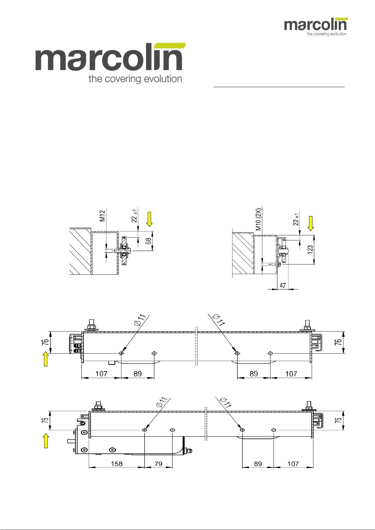
3.1 Fitting the rear pulleys - Hand-operated version for body < 8 m................................................................. 12
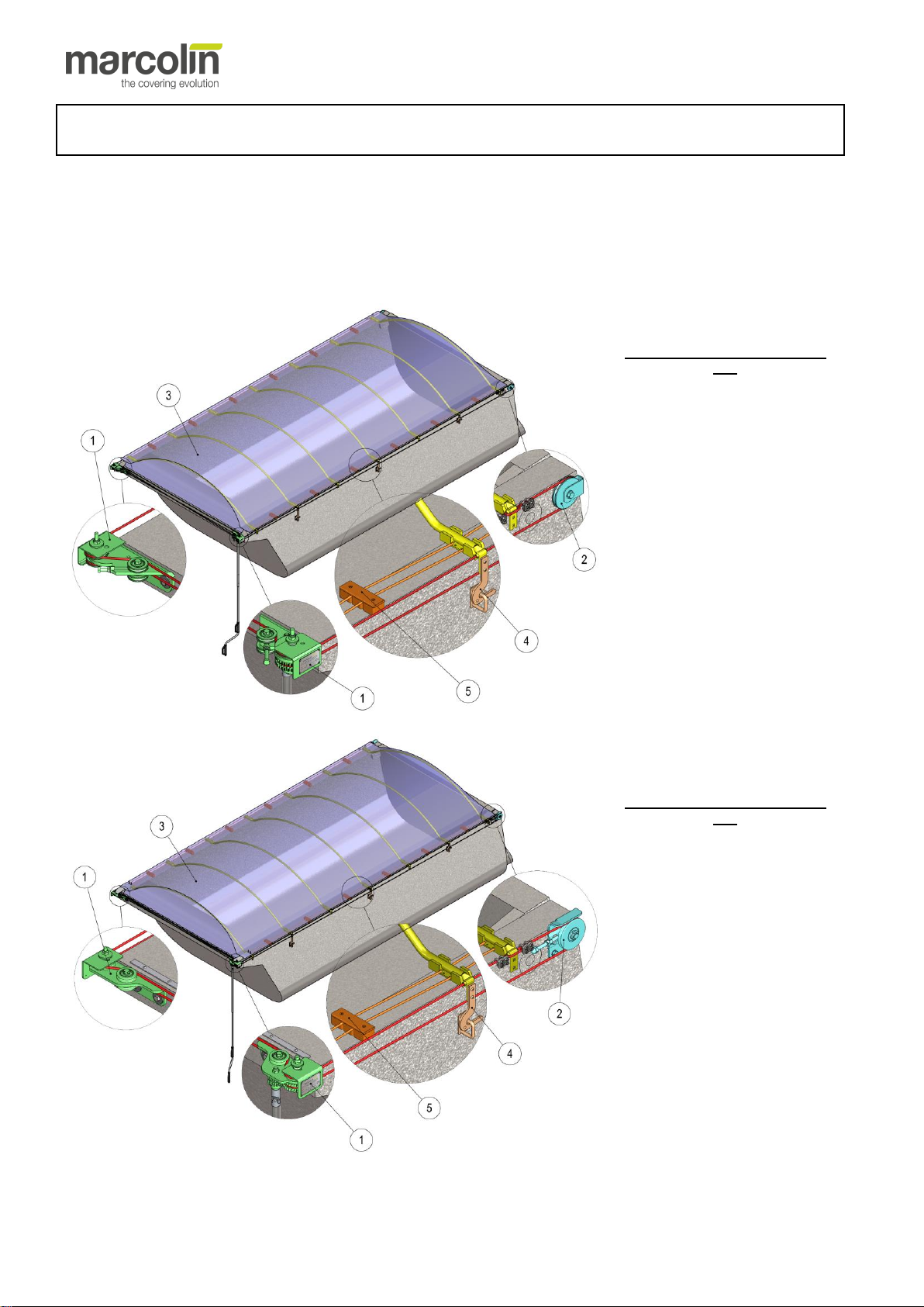
3.1.1 Fitting the rear pulleys in case of “STANDARD CABLE SYSTEM”......................................................................12
3.1.2 Fitting of the rear pulleys in case of “LOWERED CABLE SYSTEM” ...................................................................12
3.2 Installing the tensioning plates - Hand-operated version for body > 8 m and electrical version................. 13
3.2.1 Installation of the rear tensioning plates with the "NORMAL CABLE" option....................................................... 13
3.2.2 Installation of the rear tensioning plates with the "LOWERED CABLE" option....................................................13
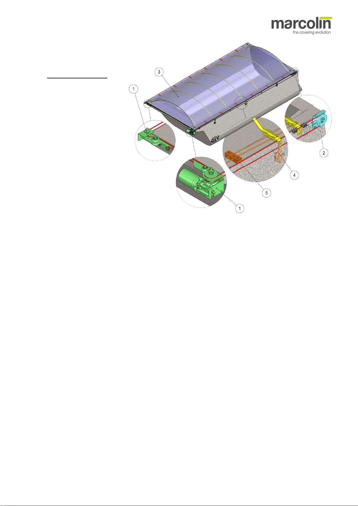
3.3 Driving system installation........................................................................................................................... 14
3.3.1 Versatility of the covering system........................................................................................................................ 14
3.3.2 Working and preparation of the cab guard with “STANDARD CABLES” .............................................................14
3.3.3 Working and preparation of the cab guard with “LOWERED CABLES”............................................................... 16
3.3.4 Supports fitting..................................................................................................................................................... 17
3.4 Installation of the steel cable ....................................................................................................................... 19
3.4.1 Run of the steel cable..........................................................................................................................................19
3.4.2 Cable fastening.................................................................................................................................................... 22
3.4.3 Clamping the pulling bow.....................................................................................................................................23
3.4.4
Steel cable tightening up .....................................................................................................................................24
3.5 Fastening the operating rod (hand-operated covering system)................................................................... 26
3.6 Tarpaulin fastening ...................................................................................................................................... 27
3.7 Lateral hooking system for the covering...................................................................................................... 28
3.7.1 Standard closure with automatic hooking............................................................................................................28
3.7.2 Hermetic closure with elastic strings.................................................................................................................... 30
3.8 Electrical wiring for Ecotype Covering System............................................................................................ 31
3.8.1 Control Box models description........................................................................................................................... 32
3.8.2 Installation of the electrical components..............................................................................................................33
3.9 Switch panel of the machine........................................................................................................................ 35
3.9.1 Description of the Control Box.............................................................................................................................35
3.9.2 Emergency pushbutton key, safety shutdown ..................................................................................................... 36
3.9.3 Control switches of the Control Box for operators ...............................................................................................36
3.9.4 Description of the radio control system................................................................................................................36
3.9.5 Reprogramming the "TX MARCOLIN" radio remote control................................................................................ 37
3.9.6 Unfold the Ecotype tarpaulin for covering the tipper body................................................................................... 37
3.9.7 Interruption of machine operations ...................................................................................................................... 37
3.9.8 How do you stop the machine in case of emergency? ........................................................................................37
3.9.9 Restoring of standard operative conditions.......................................................................................................... 38
3.9.10 Machine stop in safety conditions......................................................................................................................38
3.9.11 Retraction of the Ecotype tarpaulin for uncovering the tipper body ...................................................................38
3.9.12 How do you interrupt the machine operations? .................................................................................................38
3.9.13 How do you stop the machine in case of emergency? ......................................................................................38
3.9.14 Machine stop in safety conditions......................................................................................................................38
3.9.15 In case of empty tipper body.............................................................................................................................. 39
3.10 What is to be done, when the electric operated handling system doesn’t work?...................................... 40
3.10.1 Replacement of the internal fuse in emergency case........................................................................................40
C
Ch
ha
ap
pt
te
er
r
4
4
Accessory equipment installation..............................................................41
4.1 Automatic rear closing system..................................................................................................................... 41
4.1.1 Installation of reinforcing brackets for automatic rear closing in case of lowered cables.....................................42
4.2 Automatic “Wheel-Hooking System”............................................................................................................ 43

Installation manual - Ecotype - 5
4.3 Windsafe hooking system.............................................................................................................................45
4.3.1 Installing the rear tensioning plate with 70 mm pulley with "STANDARD CABLE SYSTEM” ...............................45
4.3.2 Installing the rear tensioning plate with 70 mm pulley with "LOWERED CABLE SYSTEM”.................................46
4.3.3 Installing hooks and side guides..........................................................................................................................47
C
Ch
ha
ap
pt
te
er
r
5
5
Maintenance work of the Ecotype Covering System................................49
5.1 Bow replacement..........................................................................................................................................49
5.2 Tarpaulin replacement..................................................................................................................................50
5.3 Steel cable replacement...............................................................................................................................50
5.4 Extraordinary maintenance work - Operations to be carried out on the customer’s covering system .........51
5.4.1 General tightening up of the screw connections ..................................................................................................51
5.4.2 Checking of the conservation status of metal structure and bows .......................................................................51
5.4.3 Checking of the tarpaulin conservation status......................................................................................................51
5.4.4 Checking of the elastic strings or the automatic safety hooks (only if installed)...................................................51
5.4.5 Checking of the contact plates (only if installed)..................................................................................................51
5.4.6 Checking of the sliding conditions of the tarpaulin...............................................................................................51
5.4.7 Thoroughly checking of the pulleys......................................................................................................................51
5.4.8 Replacement of broken or damaged fastening hooks on the outer board wall (only when the components are
present).........................................................................................................................................................................52
5.4.9 Lubricate and grease thoroughly the covering system.........................................................................................52
5.4.10 Filling in the machine control register.................................................................................................................52
5.5 Troubleshooting table for electrically operated covering system .................................................................53
C
Ch
ha
ap
pt
te
er
r
6
6
Enclosures...................................................................................................55
6.1 Reference diagram for electrical connections ..............................................................................................55

6 - Installation manual - Ecotype
C
Ch
ha
ap
pt
te
er
r
1
1
INTRODUCTION
1.1 Introduction
Load securing, for example of aggregates, during the freight transport on road is required by law.
Marcolin Covering s.r.l. has developed the Ecotype Covering System, which fulfils the legal obligation and satisfies practical
and functional needs of its user.
This manual provides all the necessary instructions for a safe application and for keeping fully functional the Ecotype
Covering System through the planned periodic maintenance.
Thank you for having chosen the Ecotype Covering System of Marcolin Covering s.r.l.!
1.2 Important information if purchasing the “lowered cable system”
The Ecotype Covering is also available with “lowered cables”.
The system is intended for lowering the cable run of the upper steel cable which pulls the covering system. The cable run is
lowered by approx. 22 mm under the body upper edge compared to the standard cable run which is approx. 11 mm over the
body upper edge.
This option aims at fulfilling the requirements of our Customers and eliminating the breakage problems of the steel cable as
a result of cable crushing during the normal loading operations.
In case of installation of the “lowered cable” covering system all the height indications mentioned in this installation
manual regarding the positioning of the machinery on the front side and the tension plates or guide pulleys on the rear side
have to be increased by 33 mm.
See details in paragraphs 3.1.2 and 3.3.3 .
1.3 Commitments of the machinery deliverer to the end-user
As dealer of Marcolin Covering s.r.l. your company finalizes the sale, the installation, the delivery of the covering system to
the end-user and the customer service.
The handing over procedure of the machine to the end-user is an important happening both for the dealer and for the user.
For this reason it is relevant that the selling operation is carried out with understanding and collaboration.
Following operations are mandatory for the machine deliverer:
•Carrying out the teaching and training course with final examination (in oral or written form at yours own discretion) to
pass by the machine operator.
The teaching and training course can be considered as passed when the machine operator has successfully answered your
questions and has personally performed several operating cycles on the machine.
•Issuing the own EC Declaration of Conformity.
•Handing over the own EC Declaration of Conformity to the end-user (not the one issued by Marcolin Covering s.r.l.
because it doesn’t cover any civil and criminal liability arising from the installation and the start-up work of the machine).
•Handing over the user manual and any other documentation received by Marcolin Covering s.r.l. together with the
covering system to the end-user.
1.3.1 The teaching and training course for the end-user must include the following items:
The end-user has to be informed about the great importance of the following operations:
•recognizing the own machine;
•knowing well the piece parts the machine is made of and their specific function and application.
The end-user has to receive an appropriate information about following items:
•machine’s risk and danger areas;
•actions which are absolutely forbidden;
•the permitted proper handling and the prohibited misuse of the machine;
•components regarding the operational security.
The end-user has to receive proper instructions about the following activities:
•turning on and off the control switches;
•the machine workings by processing some operating cycles;
•the processing of the maintenance actions permitted by the manufacturer in safety conditions (fuse replacing);
•the processing of the ordinary maintenance of the machine;

Installation manual - Ecotype - 7
•that it is mandatory to process EVERY YEAR at least one extraordinary maintenance at the manufacturer’s workshops
or at workshops authorised by the manufacturer;
•that the end-user must keep the maintenance check register updated.
It has to be repeated several times that:
•all the instructions given during the training course can be looked up in the user manual that has to be entirely read and
learnt by the end-user before using the machine for the first time.
•that in case of selling of the machine the end-user is obliged to:
ocarry out a teaching course to the new machine owner;
ohand over this installation manual and the EC Declaration of Conformity to the new machine owner.
It is mandatory to obtain from the receiver the signed declaration “ASSUMPTION OF LIABILITY BY ACCEPTANCE
OF THE MACHINE” to find under chapter 1.8.9 of the operating manual, to make a copy of it and to send it to Marcolin
Covering s.r.l. as acknowledgement of acceptance and beginning of the term of guarantee.

8 - Installation manual - Ecotype
C
Ch
ha
ap
pt
te
er
r
2
2
THE ECOTYPE COVERING SYSTEM
2.1 Covering system components
THE INSTALLER IS OBLIGED TO KNOW THE CONTENT OF THE MANUAL HANDED OVER TO THE OPERATOR
TOGETHER WITH EACH COVERING SYSTEM AND TO OBSERVE COMPLETELY PROHIBITIONS,
REGULATIONS AND ADVICES.
Before installing the covering system it is essential to know well its characteristics and the various elements the system is
made of. The figure below shows the main parts of the covering system.
HAND-OPERATED VERSION <
8 m
1. Front covering drive system,
with cable tensioning and
operating rod.
2. Pulley and bracket for the
return of the cable at the rear.
3. Tarpaulin of variable size
according to tipper body length.
4. Covering fastening system
(depending on the model, it
could be supplied with a
hermetic closure with elastic
strings).
5. Folding and lifting system of the
tarpaulin.
HAND-OPERATED VERSION >
8 m
1. Front covering drive system,
with operating rod.
2. Rear cable tensioning system.
3. Tarpaulin of variable size
according to tipper body length.
4. Covering fastening system
(depending on the model, it
could be supplied with a
hermetic closure with elastic
strings).
5. Folding and lifting system of the
tarpaulin.

Installation manual - Ecotype - 9
ELECTRICAL VERSION
1. Front covering drive system.
2. Rear cable tensioning system.
3. Tarpaulin of variable size
according to tipper body
length.
4. Covering fastening system
(depending on the model, it
could be supplied with a
hermetic closure with elastic
strings).
5. Folding and lifting system of
the tarpaulin

10 - Installation manual - Ecotype
2.2 Interventions and machine modifications
WARNING!
IT IS ABSOLUTELY FORBIDDEN TO MODIFY THE MACHINE!
Whoever modifies the machine becomes its manufacturer and assumes all civil and criminal liabilities
provided for by law in force.
Whoever modifies the machine assumes the obligation to issue:
•a new CE marking,
•new installation and user manual for the end-user,
•an own EC Declaration of Conformity.
The replacement of whatever is usually called spare part is not considered as a modification.
2.3 Tipper body construction features for a good installation
Before installing the covering system check following items:
•The linearity of all the upper edge of the tipper body.
•The accuracy of flatness between the installation area of the covering (protrusion on the front side of the tipper body,
usually called cab guard) and the remaining part of the tipper body along which the covering should slide.
•The integrity of the upper edge of the tipper body.
•The absence of any projecting element all along the upper edge.
•The absence of any sharp edge.
NO!
YES!

Installation manual - Ecotype - 11
2.4 Installation of the optional idler pulley system
If linearity between the cabin guard and the top edge of the sides is not possible (pic. A) you can proceed as follows:
Request to Marcolin Covering s.r.l. an optional idler pulley system (pic. B).
The optional idler system allows to deflect the steel cable from the top edge of the cab
guard to the top edge level of the side walls in order to obtain a linear sliding movement of
the covering.
Obviously, in this case, the covering occupies a part of the tipper body and the tarpaulin
must be fastened over the cab guard.
Another solution is fastening the front boxes at the level of the side edge and, to prevent the front steel cables from
hitting the cylinder or spare tyre bracket, creating deflections with pulleys (pic. C), so that the steel cable passes very
close to the frontal sideboard.
Pic. C
CYLINDER
CYLINDER
Pic. A
Pic. B

12 - Installation manual - Ecotype
C
Ch
ha
ap
pt
te
er
r
3
3
THE ECOTYPE COVERING SYSTEM INSTALLATION
IMPORTANT!
Before starting the installation process, check the covering model at your disposal and examine
carefully any particular case that can occur.
3.1 Fitting the rear pulleys - Hand-operated version for body < 8 m
3.1.1 Fitting the rear pulleys in case of “STANDARD CABLE SYSTEM”
The installation of the rear pulleys requires a special attention in order to avoid to create any obstacle for mobile elements
(i.e. tailgate with lateral opening system).
The best installation position for the plate is the one as close as possible to the rear edge, but at a sufficient distance for
avoiding to be an obstacle for hinges.
WARNING!
A wrong positioning of the pulleys could cause damages for the covering or for the tipper body.
If in doubt, carry out mobility trials of the rear mobile elements to avoid unpleasant surprises.
•For a proper working of the covering system the axis of the lower fastening hole of the
pulley has to be positioned at a distance of 35 mm from the upper edge of the tipper
body.
•Drill a M12 threaded hole on the lateral board wall, aligning it with the pulley hole.
•Fasten the pulley and U-bolt with the hexagon head screw M12x60 supplied with the
system.
•
SECTION A-A
Note:
During its working life the structure is subject to vibrations and stress; therefore, it is recommended to apply a medium
or strong threadlocker Loctite®liquid.
•Repeat now the pulley fastening operation on the opposite board wall.
Note:
The proper fitting of the rear pulleys is of primary importance since it is binding for the positioning of all the
subsequent element.
3.1.2 Fitting of the rear pulleys in case of “LOWERED CABLE SYSTEM”
For installing the LOWERED CABLE covering system the
height indication of 35 mm given for installing the standard
cable covering system has to be increased by 33 mm.
The installing height for lowered cable system becomes 68
mm➔

Installation manual - Ecotype - 13
3.2 Installing the tensioning plates - Hand-operated version for body > 8 m and electrical
version
3.2.1 Installation of the rear tensioning plates with the "NORMAL CABLE" option
When installing the rear tensioning plate, pay special attention not to impede the movement of other moveable parts (e.g..
swing doors).
The most appropriate location of the plate is as close as possible to the rear edge, but, at the same time, at such a distance
as not to hinder the movement of hinges and similar.
WARNING!
Incorrect placement could cause damage to the covering itself or to the body.
If in doubt, it is advisable to try out the movement of the rear moving parts to avoid unpleasant
surprises.
1. For the correct operation of the covering, ensure that the axis of the lower plate fixing
holes is located at a distance of 90 mm from the upper edge of the body.
2. Proceed with two M10 threaded holes on the side wall, in correspondence with the
holes on the plate.
3. Secure the plate using the bevelled head screws M10x40 provided with the kit,
ensuring that the tensioning screw is facing the front of the vehicle.
SECTION A-A
Note:
During its lifetime, the structure will be subject to vibrations and stresses. It is therefore recommended to use a
medium or high strength thread locking fluid.
4. Mount the plate on the opposite side using the same procedure.
Note:
The correct installation of the rear plates is essential because it affects the placement of all other components.
3.2.2 Installation of the rear tensioning plates with the "LOWERED CABLE" option
When mounting the cover with the LOWERED
CABLE option, you need to add 33 mm to the
distance (90 mm) required by the normal cable
option.
The installation distance for the lowered cable
option is 123 mm ➔

14 - Installation manual - Ecotype
3.3 Driving system installation
The covering driving system must be placed on the front side of the tipper body next to the cab guard.
The driving system is available either hand-operated or motor-operated; in any case the installation process is similar.
3.3.1 Versatility of the covering system
In order to meet the various market requirements our covering system has been designed and manufactured for being
installed with the driving unit either on the right or on the left side of the cab guard.
The procedure is the same for both assembly configurations, only the positioning of the driving system requires a special
attention.
Note:
Normally, installing the covering system, the positioning of the driving system should be on the left side (in relation to
the driving direction) of the cab guard, as it is proved that in this position the driving unit is easy accessible for the
driver when he gets out of the vehicle, and this especially in case of hand-operated covering system.
In this manual, reference will be made to standard assembly of the covering system, which is on the left of the cab guard.
For installing on the opposite side, carry out the mirror-imaged activities on the opposite side.
3.3.2 Working and preparation of the cab guard with “STANDARD CABLES”
The type of work which has to be done on the cab guard is the same for both versions available for the covering system
(manual or motorised version).
WARNING!
First, check the taper of the body, and specifically that the front side of the body is aligned with
the edge of the side wall.
After determining the positioning of the left and right supports, it is possible to intervene on the body for the installation of the
cover.
HAND-OPERATED VERSION for tipper body length < 8 m:
SEC. B-B
SEC. A-A

Installation manual - Ecotype - 15
HAND OPERATED VERSION for tipper body length > 8 m:
SEZ. B-B
SEZ. A-A
ELECTRIC VERSION:
•Drill holes (Ø 11) of the fastening seats according to the dimensions shown in the figure above.
•Fasten the supports with the screws and check that the distance between the two rear pulleys which will cycle through
the ropes, lines up front.
At this point, everything is ready for housing the various components, as indicated subsequently.

16 - Installation manual - Ecotype
3.3.3 Working and preparation of the cab guard with “LOWERED CABLES”
Add 33 mm. to the positioning height (from 43 mm to 76 mm).
HAND OPERATED VERSION for tipper body length < 8 m:
SEC. B-B
SEC. A-A
HAND OPERATED VERSION for tipper body length > 8 m:
SEC. B-B
SEC. A-A

Installation manual - Ecotype - 17
ELECTRIC VERSION:
SEZ. B-B
SEZ. A-A
3.3.4 Supports fitting
Firstly, install the LH control support, which must be positioned on the left part (with respect to the direction of travel):
•Position the left support as shown in the figure, according to the previously prepared holes.
•Fasten the support with the two screws and self-locking nuts supplied with the system.
Then fasten the right support.
•Position the support as shown in the figure according to the previously prepared holes.
•Fasten the support with the two screws and self-locking nuts supplied with the system.
HAND OPERATED
VERSION for tipper body
length < 8 m
RH Support
LH Control Support

18 - Installation manual - Ecotype
HAND OPERATED VERSION
for tipper body length > 8 m
RH Support
LH Control Support
ELECTRIC VERSION
RH Support
LH Control Support

Installation manual - Ecotype - 19
3.4 Installation of the steel cable
The covering systems of Marcolin Covering s.r.l. are supplied already preassembled. Therefore, after having placed the
covering on the tipper body, it is only necessary to pull out one by one the iron rods that keeps together the bows and to pull
the steel cable through the holes of the bow supports.
The main component that makes possible the proper covering functioning is the steel cable.
CAUTION!
During the installing activities of the steel cable the use of suitable protective gloves is mandatory in
order to avoid any injury to hands due to a possible fraying of the steel cable mesh.
PAY ATTENTION!
This activity is one of the most important for the proper workings of the tarpaulin.
The better the alignment, the easier the handling of the tarpaulin, in case of hand-operated version, and
the lesser the motor effort in case of electrically-operated version.
Before proceeding with the steel cable installation, it is necessary to carry out some operations.
Positioning of the covering:
•Remove any packing;
•Ensure the correct orientation of the tarpaulin (front –rear).
•Position the first pulling bow exactly perpendicular to the edges of the tipper body.
Note:
Pay close attention while fixing the pulling bow, because a misalignment could compromise the covering workings.
3.4.1 Run of the steel cable
Scrupulously follow the instructions below for positioning the steel cable.
For convenience insert the whole length of the steel cable, between the various elements, operating as shown in the
following figures.
CROSS THE CABLE AT
THE FRONT
Body < 8 m

20 - Installation manual - Ecotype
Note:
The position of the cable is the same, both for the manual and motorised versions.
Note:
In the absence of our directive specifications, the cable must be passed through the outermost hole.
The bows holding up the tarpaulin have on their ends suitable bow supports for an
easy sliding of the covering along the upper edge of the tipper body. These supports
have at their outside a hole through which the steel cable runs.
1) BOW
2) BOW SUPPORT WITH SLIDING PART
Body > 8 m
CROSS THE CABLE AT
THE FRONT
Other manuals for Ecotype
1
This manual suits for next models
3
Table of contents
Other MARCOLIN Industrial Equipment manuals
Popular Industrial Equipment manuals by other brands

Bauer
Bauer 19121E-B owner's manual

Crosby
Crosby Gunnebo Shackle SA Classic user manual

Graco
Graco XM PFP Instructions - parts

schmersal
schmersal AZM201Z-CC-T-1P2PW-DU Instructions for operation

Enovative Technologies
Enovative Technologies DC000A Installation and operation manual

Eaton
Eaton SVC-T3 Instruction leaflet