3INSTALLATION
Installation Instructions
CAUTION: BE SURE TO READ!
• Keep this appliance area free and clear of com-
bustibles.
• Do not obstruct the ow of combustion and ven-
tilation air.
• Allow adequate ventilation to unit. Install under
exhaust hood.
• Keep this manual for future reference.
• This installation must conform with local codes
or, in the absence of local codes, with National
Fuel Gas Code, ANSI Z223.1 – latest edition; or
the Natural Gas Installation Code, CAN/CGA–
B149.1; or the Propane Installation Code, CAN/
CGA-B149.2, as applicable.
• The griddle and its individual shuto valve must
be disconnected from the gas supply piping sys-
tem during any pressure testing of that system
at test pressure in excess of ½ psig (3.45 k/Pa).
• The griddle must be isolated from the gas supply
system by closing its individual manual shuto
valve during any pressure testing of the gas sup-
ply piping system at test pressures equal to or
less than ½” psig (3.45 k/PA).
• This unit is serviceable from the front. Do not
install in such a manner that a service person
cannot remove front panels if provided.
• When installed, this appliance must be electrical-
ly grounded in accordance with local codes, or,
in the absence of local codes, with the National
Electric Code, ANSI/NFPA No. 70 – latest edition.
• In Canada, this installation must conform to
C.S.A. Standard C22.2 Canadian Electrical Code.
• The wiring diagram adhesive label is located on
the inside of the control box cover.
• The product must be installed in a room with ad-
equate air supply for complete gas combustion.
• Do not place on or directly against the unit any
objects that would block air openings into the
combustion chamber.
• Suitable for use on combustible oors.
• Clearances from both combustible and noncom-
bustible construction are 0” (0 mm) from side
walls, 10” (254 mm) from rear wall.
• This unit has a exible cord wired into electrical
system.
GENERAL INSTALLATION
1. Remove carton from skid, being careful not to dent or
scratch nished surface of the unit.
2. Inspect unit carefully for shipping damage. File clam
with carrier immediately if damage is found.
3. Remove screws holding unit to skid.
4. Transfer unit to desired position and make level and
steady by adjusting feet to compensate for oor ir-
regularities. Bolt the ange feet to the oor.
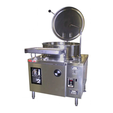
5. Raise skillet cover to full open position. Raise skillet
by turning crank clockwise. Check to make sure burn-
ers and carryover tube are in position and securely
seated.
6. Lower skillet by turning hand crank counterclockwise
until fully seated on frame. Skillet is equipped with
interlock switch, which does not permit burners to ig-
nite until skillet is lowered to less than 10o o normal
horizontal cooking position.
7. Gas service conditions:
DO NOT CONNECT GAS LINES. Only qualied in-
staller or service person should make the instal-
lation.
a. This unit is factory-adjusted for gas consump-
tion of 93,000 BTU/Hour (on 30 gallon units) or
126,000 BTU/Hour (on 40 gallon units) at the
pressure indicated. Please read rating plate on
top of control box. If this plate is marked for a dif-
ferent gas than that supplied, notify your dealer
immediately.
b. Use new 3/4 I.P.S. iron or steel pipe comply-
ing with ANSI Standard for wrought-steel and
wrought-iron Pipe B36- latest edition, properly
threaded, reamed and free from chips, oil and
dirt. If pipe dope is used, apply a moderate
amount, leaving two end threads bare. Gas con-
nection is on the rear of the right console. Pipe in
a gas shut-o valve accessible to the operator.
c. Natural gas units are equipped with a pressure
regulator factory-adjusted to give 3.5” (89mm)
water column manifold pressure. The supply
pressure must be at leaset 7” (178mm) water
column pressure.
