Marland Clutch CEUS M Series User manual

Completely Enclosed Continuous Operation
No “Down-Time” Lubrication Maintenance
CEUS-Series “M” CECON®Clutches
Service & Installation Instructions
P-1346-2-MC
Bulletin C-300M

2Marland Clutch • 800-216-3515 P-1346-2-MC • 1/18
Failure to follow these
instructions may result in product damage,
equipment damage, and serious or fatal injury to
personnel.
Installation, Lubrication,
and Maintenance
General
Marland CECON Clutches are designed for continuous
operation 24 hours a day for a whole year or longer,
if required. Since such continuous operation is
directly influenced by the care observed in installation,
lubrication, and maintenance, it is important that the
following recommendations be used as the basis for
proper care of CECON Clutch units.
As soon as the unit has been received, examine it
carefully for damage in transit and report any breakage
discovered to the transit company at once.
All tags and bulletins attached to the unit should be
carefully read before placing the unit in operation and
then filed for future reference.
Care must be taken not to place
the unit in operation until it has been lled with oil
of proper specication to the static oil level. See
Step “Starting”.
The various component parts referred to in this bulletin
may be readily identified on CEUS Diagram and Parts
List.
Electrical Grounding
Tapped holes are provided for electrical grounding of
the unit. Contact Marland for the optional electrical
grounding kit.
Storage
CECON Clutch units have been coated internally with
a preservative oil to protect the internal working parts
from corrosion during shipment and a preparation
period of not more than one week after arrival at the
site before the unit is placed in regular operation. It
is not necessary to flush out the preservative oil from
the CECON housing, as this oil will be diluted by
introduction of the regular oil supply.
The shaft ends and couplings have also been coated
with a preservative oil. Do not wash this protective
coating from shaft ends or couplings.
If the unit is to be stored for a period of time,
immediately fill with the proper quantity and grade of oil
as shown on the nameplate attached to the housing.
To fill, remove two 2” pipe caps, one from each end of
the housing cover top, and pour one-half the quantity
required into one opening, the remaining half into the
opening. Replace pipe caps. To keep the unit airtight,
do not install static oil level gauge or breather-filter. Be
sure to rotate shafts at least once every two weeks.
If the unit is to be immediately installed and operated
upon its arrival at the site, proceed with the installation
as per the instructions that follow.
Foundations
Care should be taken in the selection of flexible
foundation such as light steel or timber structures as
they may produce damaging effects.
A rigid foundation such as a reinforced concrete bed
or substantial steel structure is recommended. The
top of the foundation should be flat to prevent housing
distortion.
If the CECON unit is to be mounted on a concrete
foundation, a steel base plate containing the foot
mounting bolts should first be anchored to the
foundation.
Installation
Two eyebolts are provided on the clutch housing.
These are to be used when moving, lifting, and
lowering the CECON unit into position.
CECON units should never be
handled by placing slings or chains around the
shaft extensions.
A. Direction of Rotation
The CECON unit output shaft (Part No. 26) must be
arranged for freewheeling rotation. The nameplate
attached to the clutch housing end plate identifies
the output shaft. This shaft is to be connected to
the shaft of the driven equipment.
The CECON unit input shaft (Part No. 12) is also
identified by nameplate on the clutch housing. The
input shaft is at the same end of the CECON unit as
the hand friction brake (Part No. 4). This shaft is to
be connected to the shaft of the driving equipment.
As a further precaution before proceeding with
the assembly, check the direction of freewheeling
rotation by holding the CECON input shaft (Part No.
12) stationary while trying to rotate the output shaft

Marland Clutch • 800-216-3515 P-1346-2-MC • 1/18 3
(Part No. 26) first in one direction and then in the
opposite.
Be sure the free rotation is in
the desired direction.
B. Drain Valve and Static Oil Gauge
Insert drain valve and static oil level sight gauge
before CECON unit is lowered into position. Drain
valve (Part No. 23) and static oil level sight gauge
(Part No. 40) may be located on the same or
opposite sides of the housing. Use the pipe plug
that was removed from housing as safety plug in
end of the drain valve.
C. Alignment
We recommend that the coupling hubs and sleeves
for the CECON unit shafts be sent to our factory for
mounting.
Accurate alignment of the CECON unit shafts with
the shafts of the connected equipment is most
important and should be done in accordance
with the coupling manufacturer’s instructions.
Misalignment may develop unnecessary overloads
and stresses in shafts and bearings, and can be
responsible for failure of the equipment. If Marland
Clutch has furnished the couplings, see Coupling
Data Sheet enclosed with this bulletin.
CECON Clutch unit shafts should be connected
to the driver and driven equipment shafts through
suitable sizes of double-engagement, self-aligning,
gear-type flexible couplings. Do not use couplings
of pin, flexible spring, or single-engagement types
without the approval of Marland Clutch.
Never use heavy blows on CECON unit shafts
when aligning, mounting hubs, fitting keys, etc.
Evidence of damage caused by disregard of these
instructions is readily traceable, and Marland Clutch
will not be held responsible for the failure of the
affected part or parts.
After the CECON has been lowered in place, it
is desirable to use metal shims to obtain proper
alignment of the CECON unit shafts with the
shafts of the driver and driven equipment. Locate
housing axially to provide shaft gaps per coupling
manufacturer or as shown on the certified drawing.
Use shims under feet of housing, preferably
U-shaped, to fit around mounting bolts evenly.
Tapped through holes for Jacking Screws are
provided to assist in the installation of the metal
shims.
Failure to properly shim the CECON unit housing
feet may cause the housing to distort when the
mounting bolts are tightened.
For inclined applications, refer to the certified
drawing for the approved inclined longitudinal
mounting axis. The transverse axis must be placed
in a horizontal position and checked with a spirit
level indicator.
It is important that the alignment of the CECON
unit shafts with the shafts of the driver and driven
equipment be rechecked after the final tightening of
the mounting bolts, and before the coupling sleeves
are bolted together.
After the installation has been properly aligned,
dowel the CECON unit in place by using two
dowels, locating them on the same side of the
housing. Doweling will preserve the original
alignment and proper shaft relationship should
it become necessary to remove and reinstall
the CECON unit, thus providing every possible
precaution against wrong reassembly.
Starting
A. Fill with Oil
CECON Clutch units are shipped without oil.
Before placing in operation, the unit must be filled
with oil of the grade specified on the nameplate, to
the level indicated on the static oil level sight gauge
(Part No. 40). The approximate oil capacity for
filling to the static oil level is shown on the certified
drawing and nameplate.
Oil containing high lubricity or
EP additives must not be used in clutch units.
Never use grease for internal lubrication of the
clutch. The use of improper lubricants could
cause a malfunction resulting in equipment
damage.
DEXRON III Automatic Transmission Fluid is
recommended for year-around lubrication in
Marland CECON Clutches. Any changes in lubricant
specifications will be noted on the nameplate.
To fill the unit with oil, thoroughly clean around
the 3/4” square pipe plug adjacent to the brake
handle to prevent foreign material from entering the
housing. Remove the 3/4” square head pipe plug.
Fill unit with oil through this opening, allow sufficient
time for the oil to seek its natural static level in the
housing as indicated by the STATIC oil level sight
gauge. Replace pipe plug.
Be sure oil strainer baskets (Part No. 31) are
properly seated in their housing (Part No. 32).
Replace pipe caps and hand-tighten.

4Marland Clutch • 800-216-3515 P-1346-2-MC • 1/18
Note: CECON units in sizes 5C and 1M are
furnished with two oil strainer baskets. All
other sizes are furnished with four.
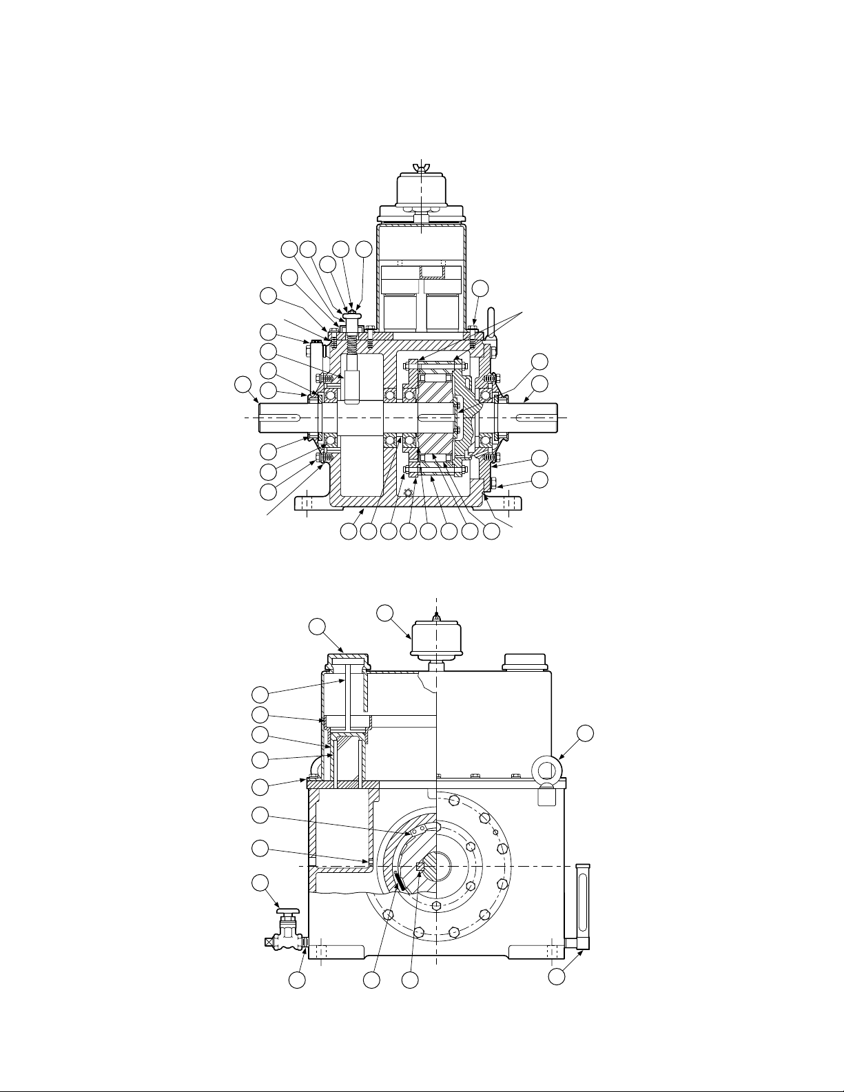
Remove the pipe plugs on housing hood (Part No.
30) and insert the breather-filter using the elbow
fittings provided.
B. Lubricate Couplings
Lubricate the couplings connecting CECON input
and output shafts to the driver and driven shafts
in accordance with the coupling manufacturer’s
instructions. If Marland Clutch has furnished the
couplings, see Coupling Data Sheet enclosed with
this bulletin.
C. Initial Startup
During the initial starting operation, check to
determine if there is any evidence of localized
heating; if the lubrication appears satisfactory; and
whether there is any vibration present due to loose
foundation bolts or misalignment of shafts. If any
correction is necessary, it should be made before
placing the CECON unit into continuous operation.
Note: Oil level may take up to ten minutes at
the maximum intended speed to stabilize.
Lubrication Maintenance
A. Oil Level Gauges
CECON units are provided with 2 oil level sight
gauges. One is located at the end of the clutch
housing to indicate the minimum oil level to be
maintained when the unit is in continuous operation,
or has been operating for at least 10 minutes at the
maximum intended speed. The other oil level gauge
is located at the bottom of the side of the clutch
housing and indicates only the static oil level.
B. Running Oil Level
During operation the CECON unit oil level should be
maintained at or above the minimum running level
as marked for the oil level sight gauge located at
the end of the clutch housing.
When the oil level is below the minimum running
level, sufficient oil should be added to bring the
level up to the indicated minimum running level. To
add oil, remove one of the 2” pipe caps from the
clutch housing hood. It is not necessary to stop the
CECON unit when adding oil.
Important: Running oil level may drop below the
minimum indicated during slow speeds of the input
shaft, such as in starter drives, creep drives, etc.
The static level indicated on the side of the housing
is sufficient for proper lubrication.
C. Renewal of Oil Strainers
Important: Running oil level will drop below the
minimum indicated if oil strainers are clogged.
Strainers may be removed while unit is in operation
by removing the 2” pipe caps at the top of housing
hood. Immediately upon removing a clogged
strainer, wash out sediment from strainer to make it
ready for use.
Improper maintenance methods are often
responsible for dirt and foreign matter getting into
the oil, and subsequently, into the CECON housing.
Keep oil supply and containers, pumps, or funnels
used for filling, clean and free from contamination.
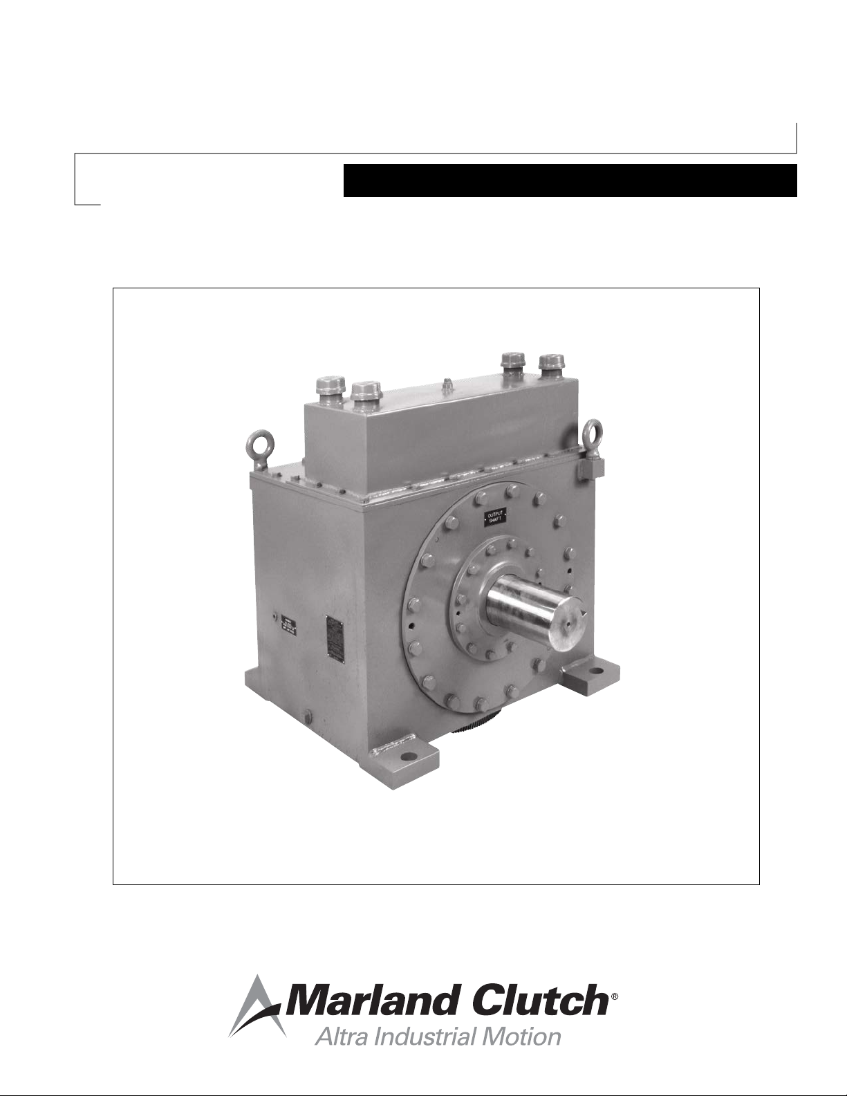
D. Sampling of Oil
To obtain long, trouble-free service from your
CECON unit, it is necessary that the lubricating oil
within the housing be clean and free from sludge
at all times. To be assured of this, make frequent
inspection of the condition of the oil by sampling
a sufficient quantity through the sampling or drain
valve (Part No. 23). Such sampling may be done
while the unit is running and does not require an
interruption of operations.
Visual observation of the running oil level gauge and
oil strainers will provide a further check on oil purity.
The frequency with which the CECON unit
lubricating oil is sampled or replaced is an important
consideration and can only be determined by
individual experience. However, it is considered
desirable to sample the lubrication several times at
weekly intervals after the unit has been placed in
operation. The results of such samplings will dictate
the frequency for future samplings, which could
possibly extend to one month intervals, but in any
event should not exceed three months.
Whenever sampling of the oil indicates
contamination by moisture or foreign matter, such
impurities may be withdrawn from the housing
through the drain valve. If the unit is in operation,
do not withdraw more than 1 quart at a time. The
amount withdrawn should be immediately replaced
with fresh specified oil. Replacement oil may be
added by removing one of the pipe caps or initial oil
fill plug.
E. Changing of Oil
Timing of oil change is determined by the results
of oil sampling. Unless results of oil sampling
suggest otherwise, the oil within the clutch should
be completely changed once a year for continuous
duty applications.

Marland Clutch • 800-216-3515 P-1346-2-MC • 1/18 5
F. Breather-Filter
The breather-filter should be cleaned at regular
intervals. The frequency of such servicing depends
upon the condition of the filter element when
examined and cleaned after a short period of
operation.
G. Couplings
Follow coupling manufacturer’s recommendations
regarding lubrication and maintenance of the
couplings.
Hand Friction Brake
In a dual drive arrangement with a turbine as the
alternate driver, the total static friction of the turbine’s
governor mechanism, bearings, and reduction gear
is usually sufficient to insure that the input shaft of
the CECON will not start to rotate when the clutch is
freewheeling.
The hand brake may be used to help keep the
alternate connected driver stationary should the static
frictional drag torque of the driver (such as a ball
bearing mounted electric motor) be lower than the cold
starting freewheeling drag torque of the CECON unit.
The hand brake must be released
before starting the alternate driver.
In a situation where the alternate driver is in rotation
carrying the load and is then shut off and the
prime driver is started and assumes the load, the
freewheeling drag torque of the CECON unit may tend
to continue the rotation of the alternate driver, though
at a lower speed than normal operating speed. If this
continued rotation is objectionable, the hand brake may
be used to gradually slow down and eventually stop
the alternate driver.
The hand brake must be released
before restarting the alternate driver.
In shipment and during normal operation of the
CECON unit, the brake is locked open against the
clutch housing and secured by a small bolt passing
through a hole in the end of the handle and retainer. To
engage the brake, remove the small bolt and move the
handle approximately 90 degrees until pressure is felt
against the hand.
Apply hand pressure only. Do not
extend the handle length with a pipe or other
means as damage may occur to the unit.
Service
Field disassembly and repair of CECON Clutch is
not recommended. Should problems occur, contact
Marland Clutch directly.
Rotating equipment is potentially
dangerous and could cause injury or damage if
not properly protected. Follow applicable codes
and regulations.

6Marland Clutch • 800-216-3515 P-1346-2-MC • 1/18
CEUS Diagram
15 17 16 18 19 20 21 22 GASKET
29
24
26
25
43
GASKET
8
7
6
5 4
3
2 1
GASKET
10
11
13
14
42
12
GASKET
9
34
33
32
31
30
28
27
41
40
37 38 39
36
35
23

Marland Clutch • 800-216-3515 P-1346-2-MC • 1/18 7
Part # Description
1Brake Stud Nut
2Brake Stud
3Brake Stud Washer
4Brake Handle
5Brake Thrust Screw
6Brake Seal Cover & Seal
7Housing Cover & Gasket
8Running Oil Level Gauge
9Brake Shoe
10 Oil Slinger
11 Shaft Seal Cover & Gasket
12 Input Shaft
13 Oil Seal
14 Ball Bearing
15 Clutch Housing
16 Bolts & Locknut for 20
17 Bearing Spacer
18 Clutch Coverplate
19 Cam Spacer
20 Outer Race & Gasket
21 Cam
22 Clutch Roller Assembly
Part # Description
23 Drain Valve
24 Housing End Plate & Gasket
25 Cam Retainer & Fasteners
26 Flanged Output Shaft
27 Oil Flow Plug
28 Clutch Stop Lug
29 Screws & Lockwashers for 24
30 Housing Hood & Gasket
31 Oil Strainer Basket
32 Oil Strainer Housing
33 Oil Tray
34 Oil Strainer Stem
35 Strainer Inspection Cap
36 Breather-Filter
37 Pipe Nipple
38 Clutch Spring
39 Clutch Cam Key
40 Static Oil Level Gauge
41 Eye Bolt
42 Screws & Lockwashers for 11
43 Screws & Lockwashers for 7

Warranty
Marland Clutch warrants that it will repair or replace (whichever it deems advisable) any product manufactured
and sold by it which proves to be defective in material or workmanship within a period of three (3) years from
date of shipment. This warranty extends only to the original purchaser and is not transferable or assignable
without Marland Clutch’s prior consent.
This warranty covers normal use and does not cover damage or defect which results from alteration, accident,
neglect, or improper installation, operation, or maintenance.
Marland Clutch’s obligation under this warranty is limited to the repair or replacement of the defective product
and in no event shall Marland Clutch be liable for consequential, indirect or incidental damages of any kind
incurred by reasons of manufacture, sale or use of any defective product. Marland Clutch either assumes nor
authorizes any other person to give any other warranty or to assume any other obligation or liability on its behalf.
P-1346-2-MC Bulletin C-300M 1/18
www.marland.com
23601 Hoover Rd.
Warren, MI. 48089
800-216-3515
This manual suits for next models
1
Table of contents