marquette hellige MicroSmart User guide

Servicing Instructions
MicroSmart
Version 2.xx
227 470 35B - SA (e)

Caution:
During repairs/service interventions,
observe the protective measures against
damage due to ESD.
* Marquette Hellige GmbH considers itself
responsible for the effects on safety,
reliability, and performance of the equip-
ment,onlyif:
- assembly operations, extensions,
readjustments, modifications, or
repairs are carried out by
Marquette Hellige GmbH or by
personsauthorizedbyMarquette-
Hellige GmbH,
- the electrical installation of the rele-
vant room complies with the applica-
ble national and local requirements,
and
- the instrument is used in accordance
with the instructions for use.
* This manual contains service information;
operating instructions are provided in the
operator’s manual of the instrument.
* This manual is in conformity with the
instrumentatprinting date.
* All rights are reserved for instruments,
circuits, techniques, and names appearing
in the manual.
©Marquette Hellige GmbH
Printed in Germany

Marquette Hellige GmbH MicroSmart V 2.xx Page 1
Servicing Instructions 227 470 35 B - 97.12
Contents
1 Documentation and nomenclature of Marquette Hellige instrument part Nos ........... 4
1.1 Configuration of instrument part No ............................... 4
1.2 Configuration of the PCB part Nos ................................. 4
1.3 Instrument status documentation (nominal status) ....................... 5
2Descriptionoftheunit................................................ 6
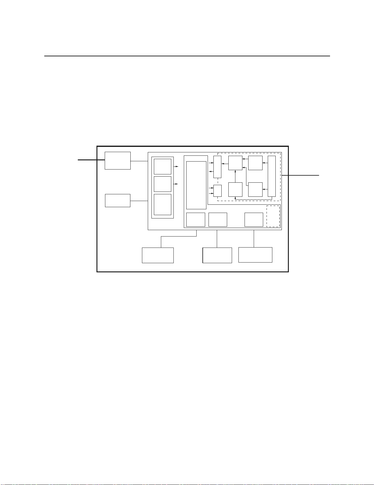
2.1 Block diagram, total unit ....................................... 7
2.2 Mechanical structure .......................................... 8
3Descriptionofthefunction ............................................ 8
3.1 Power supply module .......................................... 8
3.1.1 System inlet .......................................... 8
3.1.2 Extended range power supply .............................. 9
3.2 Battery .................................................... 9
3.3 Printed circuit board (PCB) MicroSmart ............................ 10
3.3.1 Voltage supply and monitoring ............................ 11
3.3.2 Computer .......................................... 15
3.3.3 ECG recording and pre-processing ......................... 19
3.3.4 Drive electronics and display ............................. 24
3.4 Internal interfaces ........................................... 28
3.4.1 Interface, power supply ................................. 28
3.4.2 Interface, display ..................................... 29
3.4.3 Interface, thermal array ................................. 30
3.4.4 Interface, motor ...................................... 32
3.4.5 Interface, photoelectric barrier ............................ 32
3.4.6 Interface, keyboard .................................... 33
3.4.7 Interface, ECG input ................................... 34
3.5 External interfaces ........................................... 35
3.5.1 Line inlet ........................................... 35
3.5.2 Patient input ........................................ 35
3.5.3 IR interface ......................................... 36
3.6 Delimitations .............................................. 37
4Unittestfunctions ................................................. 38
4.1 General .................................................. 38
4.2 Key test and loudspeaker test .................................... 39
4.3 Display test ................................................ 39
4.4 Motor test ................................................. 39
4.5 Recording test .............................................. 40
4.6 IR test (MicroSmart MC only) ................................... 40
4.7 Recording the results ......................................... 40

Marquette Hellige GmbH MicroSmart V 2.xx Page 2
Servicing Instructions 227 470 35 B - 97.12
4.7.1 Error codes .......................................... 41
4.8 Additional functions for final test ................................. 42
4.9 Re-locking option ............................................ 43
5Selectingthetypeofappliance ........................................ 44
5.1 General .................................................. 44
5.2 Selecting the type of appliance .................................. 45
6Repairnotes ..................................................... 46
6.1 Safety notes ............................................... 46
6.2 Component replacement ....................................... 46
7 Troubleshooting ................................................... 49
8Maintenanceandcare ............................................... 51
8.1 Technical inspection ......................................... 51
8.1.1 Visual checks ........................................ 51
8.1.2 Function checks ...................................... 52
8.2 Safety Analysis Test .......................................... 55
8.2.1 General Information .................................... 55
8.2.2 Protective earth resistance test ............................. 55
8.2.3 Measuring of leakage current ............................. 56
8.2.4 Enclosure Leakage Current Test ............................ 56
8.2.5 Patient Leakage Current Test .............................. 57
8.3 Maintenance, cleaning, disinfection ................................ 58
9Technicaldescription ............................................... 59
10Sparepartslist ................................................... 65
11Appendix ...................................................... 68

Marquette Hellige GmbH MicroSmart V 2.xx Page 3
Servicing Instructions 227 470 35 B - 97.12
Revision History
Each page of this manual has the document number followed by a revision letter, located at the top
of the page. This letter identifies the manual update level. The latest letter of the alphabet
corresponds to the most current revision of the document.
The revision history of this manual is summarized below.
Date Revision Remarks
September 1997 A Initial release of Dervicing Instructions
November 1997 B Update type of appliance, changed partnumber
of the PCBs

Marquette Hellige GmbH MicroSmart V 2.xx Page 4
Servicing Instructions 227 470 35 B - 97.12
1 Documentation and nomenclature of Marquette Hellige instrument part Nos
1.1 Configuration of instrument part No
The instrument part No comprises 8 digits, the first 6 digits determining the instrument type, the last
2 digits the instrument version. The language is determined by configuration, thus having no
influence on the part No.
E.g. Instrument Type Version
MicroSmart without measurement, IR 101 134 01
MicroSmart with measurement, IR 101 134 02
1.2 Configuration of the PCB part Nos
388 xxx yy Spare part numbers for the operative PCBs.
The instrument documentation, e.g., reference diagrams, circuit diagrams and parts lists are listed
under this part No.
The 388 number is located on the barcode label.
Configuration of the barcode labels:

Marquette Hellige GmbH MicroSmart V 2.xx Page 5
Servicing Instructions 227 470 35 B - 97.12
303 xxx yy Spare part numbers for PCBs tested especially thoroughly
303 numbers are only given to PCBs where the level of testing applied to 388 PCBs is inadequate
for implementation when servicing in the field, or where only a complete set of PCBs can be
replaced in the field.
In addition to a barcode label (388 number) 303 part Nos also have an additional label with a 303
number and are to be found in the spare parts list under this number.
389 xxx yy Replacement numbers for defective PCBs
Where servicing is required 389 PCBs are available for the replacement of some PCBs. When using
a replacement PCB (389 part No) the defective PCB is to be returned to the Freiburg factory.
Replacement PCB part Nos are included in the spare parts list.
389 PCBs have an additional adhesive label.
1.3 Instrument status documentation (nominal status)
Due to the hardware and software combination unambiguous documentation of the instrument
assembly status is necessary, also in the event of repairs.
This documentation comprises the following documents and measures:
Master Record Index (MRI)
This document is a component of this instrument documentation.
This document states the combination of permissible hardware and software for a particular
instrument version. The permissible PCB Index is given in the “Index” column with each update
delivered. Further permissible PCB Indexes are given in the “compatible” column. The PCB Index
can be found in the PCB barcode label.
Product Status Index
This document is created during manufacture. The Product Status Index documents the
hardware/software product status.

Marquette Hellige GmbH MicroSmart V 2.xx Page 6
Servicing Instructions 227 470 35 B - 97.12
2 Description of the unit
These service instructions for the V2.x version of the unit describe both the MicroSmart as well as
the MicroSmart MC. Unless a note appears to the contrary, this description applies to both the
MicroSmart and the MicroSmart MC.
MicroSmart is a portable cardiograph with integrated printer drive. It is designed to record, register
and process ECG signals. It is designed both for mains and battery operation, operation without
battery is also possible. A power supply unit and battery are integrated in the unit.
MicroSmart MC also includes in the "Auto" mode the measurement of the ECGs and registration
of the measurement results.
MicroSmart und MicroSmart MC are based on the same hardware platform.
The following versions of MicroSmart are available:
101 134 01 MicroSmart (international) 100...240V~
101 134 02 MicroSmart MC (international), measurement + IR 100...240V~
101 134 03 MicroSmart (Asia) 100...240V~
101 134 04 MicroSmart M (USA), measurement 100...240V~
101 134 05 MicroSmart MC (Asia), measurement + IR 100...240V~
101 134 06 MicroSmart (USA) 100...240V~
101 134 07 MicroSmart (inter. 5-pin) 100...240V~
The hardware consists of the following function blocks:
- MicroSmart PCB
- power supply module
- battery
- keyboard
- printer drive
The following function blocks are implemented as PCBs.
- MicroSmart PCB
- power supply
The patient input, which is a component of the MicroSmart PCB, is mounted on the power supply
module and connected to the MicroSmart PCB via a flexible supply line.
The intended use, the functions available and operation of MicroSmart are described in the
instructions for use.

Marquette Hellige GmbH MicroSmart V 2.xx Page 7
Servicing Instructions 227 470 35 B - 97.12
2.1 Block diagram, total unit
AC/DC
Battery
System inlet
Patient input
Lpl. MicroSmart
LC-Display
IRDA-
interface
Pre-amplifier
optical
coupler
DC/DC
ASIC3
ASIC2
ASIC1
ASIC1
DC/DC 5V
DC/DC 24V
MC68332
EPROM
RAM
EEPROM
Uhr
Panel-
interface Display-
interface Recorder-
interface
Battery
charge
Operator panel Recording
section

Marquette Hellige GmbH MicroSmart V 2.xx Page 8
Servicing Instructions 227 470 35 B - 97.12
2.2 Mechanical structure
The major mechanical components of MicroSmart are the top and bottom shell. The bottom shell
is the basic element carrying the following sub-assemblies:
- Power supply module with system inlet, power supply unit and patient input.
- Battery
- Thermal array drive with paper magazine
- PCB MicroSmart with display
The top shell holds the keyboard which is linked to the PCB MicroSmart via a flexible cable.
The 15-pin inlet plug for connecting the patient lead is located at the power supply module. It is
linked to the PCB MicroSmart via a flexible cable.
3 Description of the function
The description of the individual function blocks follows the Block diagram of the total unit in
chapter 1.1 and the function blocks of the P plans.
3.1 Power supply module
The power supply module comprises the following functions:
- System inlet with fuses
- Extended range power supply
- Patient input
These components are mounted on a carrier plate bolted into the bottom shell of the enclosure.
3.1.1 System inlet
The system inlet is defined as a system inlet module. It includes a three-pin IEC plug and two size
5 X 20 fuses accessible from the outside. The module is a component with snap-type function.
The system inlet is designed as "Universal Input", with the effect that no adjustment to the system
voltage ranges 100V~ ... 120V~ or 220V~ ... 240V~ is required.

Marquette Hellige GmbH MicroSmart V 2.xx Page 9
Servicing Instructions 227 470 35 B - 97.12
3.1.2 Extended range power supply
The AC/DC power supply is designed as a universal extended range power supply. The power
supply unit is purchased complete and mounted on the carrier plate. The power supply supplies an
output voltage of 15.6V, from which all required voltages are generated.
- Input voltage range: 90VAC...264VAC
- Frequency range: 49Hz...65Hz
- Output: 40W max.
- Efficiency 70%
- Output voltage: +15.6V ± 2%
- Output current: 2.6A max.
- Short-circuit-proof
- Approvals: IEC601, UL544, CSA22.2-125, VDE750
The connection between the AC/DC power supply and the PCB MicroSmart is implemented with
a 2-pin lead as follows:
- on the AC/DC power supply: plugged
-on the PCB MicroSmart: plugged
3.2 Battery
The battery is a rechargeable, maintenance-free lead battery. The battery is purchased complete and
mounted on the bottom shell of the enclosure.
- Rated voltage: 12V
- Rated capacity: 1.2Ah
The connection between the battery and the PCB MicroSmart is implemented with a 2-pin lead as
follows:
- on the battery: plugged
- on the PCB MicroSmart: plugged

Marquette Hellige GmbH MicroSmart V 2.xx Page 10
Servicing Instructions 227 470 35 B - 97.12
3.3 Printed circuit board (PCB) MicroSmart
The PCB MicroSmart holds the entire electronics of the unit. The electronics comprise the following
function groups:
- Voltage supply and monitoring
On-Off electronics
Battery charge
Input voltage monitoring
Voltage supply +5V
- Computer
Controller (Motorola 68332)
EPROM 512KByte
RAM 256KByte (MicroSmart) or 512KByte (MicroSmart MC)
Configuration memory (EEPROM) 256Byte
Reset Generation
Alarm signal output
Real-time clock, buffered
Keyboard interface
IR interface (MicroSmart MC only)
-ECG
recording and pre-processing (floating side)
- Protective input circuit
- Pre-amplifier
- AD converter
- PACE identification
- Electrode label
- Conductor label
- Filter and interface module
- Current supply
- Reference edit
- Drive electronics and display
Array control
Temperature monitoring
Motor control
Voltage supply +24V
Photoelectric barrier analysis

Marquette Hellige GmbH MicroSmart V 2.xx Page 11
Servicing Instructions 227 470 35 B - 97.12
3.3.1 Voltage supply and monitoring
On-Off electronics
Toggel-
function
ON/OFF
key
G_OFF
Uin Uout
Z502, Z503
T2
The unit is switched on and off via the ON/OFF key (on the membrane keypad). Enabling and
disabling operates via a toggle function: if the unit is switched off, press the ON/OFF key to switch
the unit on. If the unit is switched on, press the ON/OFF key to switch the unit off. The processor
can switch the unit off via the signal lead "G_OFF" if:
- the input voltage is too low (exhaustive discharge protection for the battery)
- the unit is not operated for any length of time (approx. 5 minutes)

Marquette Hellige GmbH MicroSmart V 2.xx Page 12
Servicing Instructions 227 470 35 B - 97.12
Battery charge
Voltage query
charge
control
Uin
GND GND
Uout
Battery charge
Current query
X501
T500
The battery is charged by means of a special charging IC (UC3906) for lead batteries. The circuitry
monitors the charging current and the charge voltage. The charging IC has the same "temperature
coefficient" as a lead battery, with the effect that the battery charge is optimized over the specified
temperature range. The circuit operates as a "DUAL LEVEL FLOAT CHARGER", with three
distinct charging states:
- high current bulk charge state
- over-charge state
- float state
A charging cycle begins with "high current bulk charge state". In this state the battery is charged
with a constant current ( Imax ) while the battery voltage is monitored. The "over-charge state" sets
in as soon as a certain voltage value ( U12 ) is reached. In this state the battery voltage is kept at
a certain value ( UOC ), while the charging current is monitored. If the charging current drops to
a certain value ( IOC ), the "float state" sets in. At this point in time the battery capacity has risen
to almost 100%. In the "float state" the battery voltage is regulated to a precise value ( UF).
The following values for voltage and current are selected when charging the 12V lead battery:
Imax = 250mA
U12 = 13.5V
U
OC = 14.2V
IOC = 25mA
UF= 13.7V

Marquette Hellige GmbH MicroSmart V 2.xx Page 13
Servicing Instructions 227 470 35 B - 97.12
Input voltage monitoring
Uref
Uin
Batt_Low
LED_Batt
Input voltage
monitoring
V2
V2
The input voltage is monitored. If it drops to 11.3V, the LED_Bat lights up. This indicates that the
battery is in need of recharging. If the input voltage drops further to 10.3V, the signal "Batt_low"
will be activated. This signal is scanned by the processor. If it is active, the processor will deactivate
the unit (exhaustive discharge protection for the battery).

Marquette Hellige GmbH MicroSmart V 2.xx Page 14
Servicing Instructions 227 470 35 B - 97.12
Voltage supply +5V
Switching
Regulator
Uin
GND GND
Uout
5V DC/DC converter
X500
L500
A 500KHz step-down switching regulator is used to generate the 5V voltage. The high-rate
switching frequency allows the entire circuit to be built up with SMD components. The switching
regulator is the module type LT1376. All the functions necessary for a step-down regulator are
integrated in this module.
Input voltage 10V...16V
Output voltage +5 V ± 2%
Output current min. 100 mA, max. 700 mA
Efficiency > 80%
Short-circuit-proof

Marquette Hellige GmbH MicroSmart V 2.xx Page 15
Servicing Instructions 227 470 35 B - 97.12
3.3.2 Computer
MC68332
EEPROM
IRDA-
Interface
RAM
Acoustic signal
Output
Keyboard-
Interface
Printhead
motor
display control
Control Bus
Address Bus
Data Bus
ROM
ECG-
Interface
QSPI-Bus
RTC
Controller
At the actual core of the unit is the Motorola Controller 68332 with the following integrated
components:
- CPU32, computer core, internal 32 bit register, external 16 bit processing
- TPU, independent timing processor
- QSM with SCI for the implementation of a single RS 232 interface and a serial QSPI port
with up to 16 channels.
- SIM with Chipselect generation, system monitoring, clock synthesizer

Marquette Hellige GmbH MicroSmart V 2.xx Page 16
Servicing Instructions 227 470 35 B - 97.12
EPROM
ROM comprises one 4MBit EPROM module (= 512KByte). The data bus width is 16Bit. Chipselect
is the CSBOOT of the 68332.
RAM
RAM comprises a maximum of four static RAM modules with 128KByte each. The data bus width
is 16Bit. Each RAM chip receives its own chip-select signal (separate chip-select for High and Low
Byte) from the controller. This means that the RAM address is software-configurable. The basic
MicroSmart unit is only equipped with two RAMs, corresponding to a memory area of 256KByte.
The memory capacity can be extended to 512KByte by adding two more RAMs. Access time is 70
ns, this means that access is allowed without Wait States.
EEPROM
A serial EEPROM is used for the non-volatile memory. This is connected to the QSPI interface of
the 68332. The EEPROM has a memory area of 2048 Bit. (= 256Byte)
Reset Generation
Reset Generation is implemented with an integrated monitor module. It includes the voltage
monitoring with Reset Generation.
Acoustic signal output
The MicroSmart has a sound output for acoustic status/alarm signals. The pitch is selected via a TPU
channel of the 68332 (signal name: Beep). In addition, the volume can be varied in 3 stages. Volume
is set via the 3 signals LAUT1, LAUT2 and LAUT3.
Real-time clock
Provides the time and date. During operation it is supplied by the Supply logic; when the unit is
turned off, the unit switches over automatically to a 3V lithium cell which preserves the data. The
control signals for the clock (chipselect- read/write signal) are generated directly by the controller
(MC68332).

Marquette Hellige GmbH MicroSmart V 2.xx Page 17
Servicing Instructions 227 470 35 B - 97.12
Keyboard interface
MicroSmart´s keyboard interface comprises a 5x5 matrix, although only a 4x4 matrix is required and
led to the keyboard. This allows 16 keys to be implemented. The keys are polled in cycles. To do
so, bit combinations are written into a buffer module (column) in cycles. An input module (row)
polled in cycles identifies if a key has been pressed (the combination of output pattern and input
pattern allows the pressed key to be determined).
The keyboard interface is located on the top byte of the data bus. The bits D8..D12 are used for the
keyboard (both input and output).
Both the output buffer and the input buffer are selected via a separate chipselect signal (chipselect
signal of the 68332).
The top two bits (D13...D15) of the input buffer are assigned with additional functions:
D13: Hardware configuration bit (function undetermined) for future extensions
Default: 0
D14: Battery monitor bit: D14 = 1 ==> battery voltage < 11.3V
D14 = 0 ==> battery voltage > 11.3V
D15: Battery monitor bit: D15 = 1 ==> battery voltage < 10.3V
D15 = 0 ==> battery voltage > 10.3V
In addition to the 16 keys of the 4x4 matrix, the keyboard includes a key for switching the unit on
and off. Due to its special hardware configuration, this key is not integrated in the matrix.

Marquette Hellige GmbH MicroSmart V 2.xx Page 18
Servicing Instructions 227 470 35 B - 97.12
The keyboard also includes 4 LEDs which are selected via the keyboard interface.
Line LED: This LED is supplied directly from the 15V of the power supply. It shows
whether the unit is mains-operated (LED on) or supplied from battery (LED
off).
LED LOBAT: This LED is switched on and off by the controller. It shows that the battery
is in need of a recharge. A LOW level at the signal LED_LOBAT_ activates
the LED.
LED START: This LED indicates the status of the unit. It means that the unit is in an active
state ! (processing, printing, etc. in progress). A LOW level at the signal
LED_START_ activates the LED.
LED STOP: This LED indicates the status of the unit. It means that the unit is in a passive
state ! (processing, printing, etc. not in progress). A LOW level at the signal
LED_STOP_ activates the LED.
IR interface
The MicroSmart MC is equipped with an IRDA interface.
The IRDA interface is selected via the RS232 interface of the 68332.
(Signals TXD and RXD of the ’332).
In addition, an output port of the ’332 determines if the IRDA module (TOI3232) is in the
configuration or in the communication mode.
Configuration signal: IR_BR_D = 0 ==> communication mode
IR_BR_D = 1 ==> configuration mode
Table of contents
Popular Medical Equipment manuals by other brands

ADC
ADC Adscope 600 Instructions for use

Synapse
Synapse NeuRx Information and Instruction Manual

Dentsply Sirona
Dentsply Sirona Purevac HVE Positioning Guide

Laica
Laica SB2200 Instructions and guarantee

Control Bionics
Control Bionics Neuronode Trilogy Attachment instructions

Vancare
Vancare Vander-Lift 450 Maintenance manual