Marson 150SP Operation manual

This is our most powerful air/hydraulic threaded insert setting tool. This
spin-pull tool automatically threads the fastener onto the mandrel. Press
the trigger just once and the fastener is installed. Reverse the trigger and
the mandrel spins out of the fastener. The 39221 features a totally
adjustable stroke length to suit any grip range and a swivel air inlet for
increased mobility. No complicated tear down is required to adjust the
stroke or to change thread sizes…both adjustments are done outside the
tool. The 39221 handles rivet-nut sizes 4-40”through ½-20”and 3.5mm
through 12mm in aluminum or steel. 6-32” through 3/18-16” mandrels and
nosepieces are included. Weight: 6 lbs.
Tool also available with metric mandrels and nosepieces, part number 39222
CAUTION:
ALWAYS WEAR SAFETY GLASSES WHEN OPERATING TOOL
150SP (39221)
Thread Setter Tool (Spin Pull)
Instructions & Parts List
44 Campanelli Parkway
Stoughton, MA 02072
Customer Service: 800-343-3633
www.alcoafasteningsystems.com
All manuals and user guides at all-guides.com
all-guides.com

AIR FEED
Use only compressed air. Check airline for damage from humidity &
contaminants. In order to protect the tool from premature wear it is
recommended a filter separator & regulator assembly be used. A lubricator is not
necessary but a separator is highly recommended. Normal working pressure is
85-95 PSI. Air connection size ¼-20” NPT.
WARNING: Do not use air supply greater than recommended or tool
may be damaged or burst. Do not use oxygen, combustible gases or
bottled gases as a source for this tool. Gases could cause the tool to
explode.
CAUTION:
ALWAYS WEAR SAFETY GLASSES WHEN OPERATING TOOL
Main Components
A: Mandrel
B: Nosepiece
C: Nosepiece Lock Nut
D: Rocker Trigger 1. Upset 2. Reverse
E: Mandrel Adapter Release
F: Balancer Connector
G: Stroke Adjustment Ring
H: Pneumatic Motor
I: Fluid Plug
J: Air Connection (1/4-20 NPT female)
J
All manuals and user guides at all-guides.com

MAINTENANCE
ADDITION OF HYDRAULIC FLUID
Tool is shipped with oil. If it becomes necessary to add oil, follow this procedure. Put tool
in a horizontal position. Remove plug using the supplied 5 1/2mm hex key (Fig.1).
Screw hydraulic fluid bottle container (Fig.2) into fluid plug receptacle. Oil level should
reach edge of fill hole. With container still attached, rock tool in horizontal position to
remove any air pockets. Add more fluid if necessary. IMPORTANT: Use only an Anti-
Foaming hydraulic fluid such Mobil DTE 24 or equivalent air tool oil.
Installing Mandrel and Nosepiece
Setting up Insert and Stroke Adjustment
Fig. 1. Loosen the lock nut using a 22mm wrench (Fig 3) and remove the nosepiece.
Fig. 2. Insert supplied pin through the hole as shown (Fig. 4) and pull back and hold while unscrewing the mandrel
Fig. 3. While holding back supplied pin pull back and hold while screwing in mandrel (Fig. 5)
(note: when mandrel is fully seated you will hear a click sound) release pin and remove.
Fig. 4. Screw locking nut onto nosepiece and replace the nosepiece back onto the tool. (Fig 6)
Fig.1
Fig.2
All manuals and user guides at all-guides.com

Adjusting Stroke Length
After installing correct size mandrel and nosepiece into tool (See Fig. 3-6) Turn the stroke adjustment
notched ring using supplied spanner wrench all the way towards the minus (-) sign until it stops (Fig. 7).
Thread insert onto tool with flange facing nosepiece while applying light pressure towards mandrel. Tool
will automatically thread insert onto mandrel. Be sure mandrel thread is flush or sticking out a
maximum of 1 thread out of the insert (Fig. 8). Adjust nosepiece by loosening lock nut and rotating
nosepiece so that it is up against insert flange. Once this adjustment is set tighten up the lock nut against
the nosepiece.
Insert into sample application (Fig. 9). and actuate trigger (1). Making slight adjustments begin turning
stroke adjustment toward the plus sign (+) then actuate trigger (2) until desired bulge (Fig. 10) is formed
on the blind side. (blind side upset should be fairly flat up against the application with no upward
cupping of the formed bulge). Your tool is now properly set for the insert size and alloy you are using.
Press trigger (2) to reverse tool and remove it from the installed insert. CAUTION: after all adjustments
are properly made it only takes one stroke of the tool to set the insert properly. A second stroke may
break the mandrel and damage the insert threads.
3 Simple steps to set Threaded Insert
All manuals and user guides at all-guides.com

150 SP (39221) TOOL BREAKDOWN AND PARTS LIST
All manuals and user guides at all-guides.com

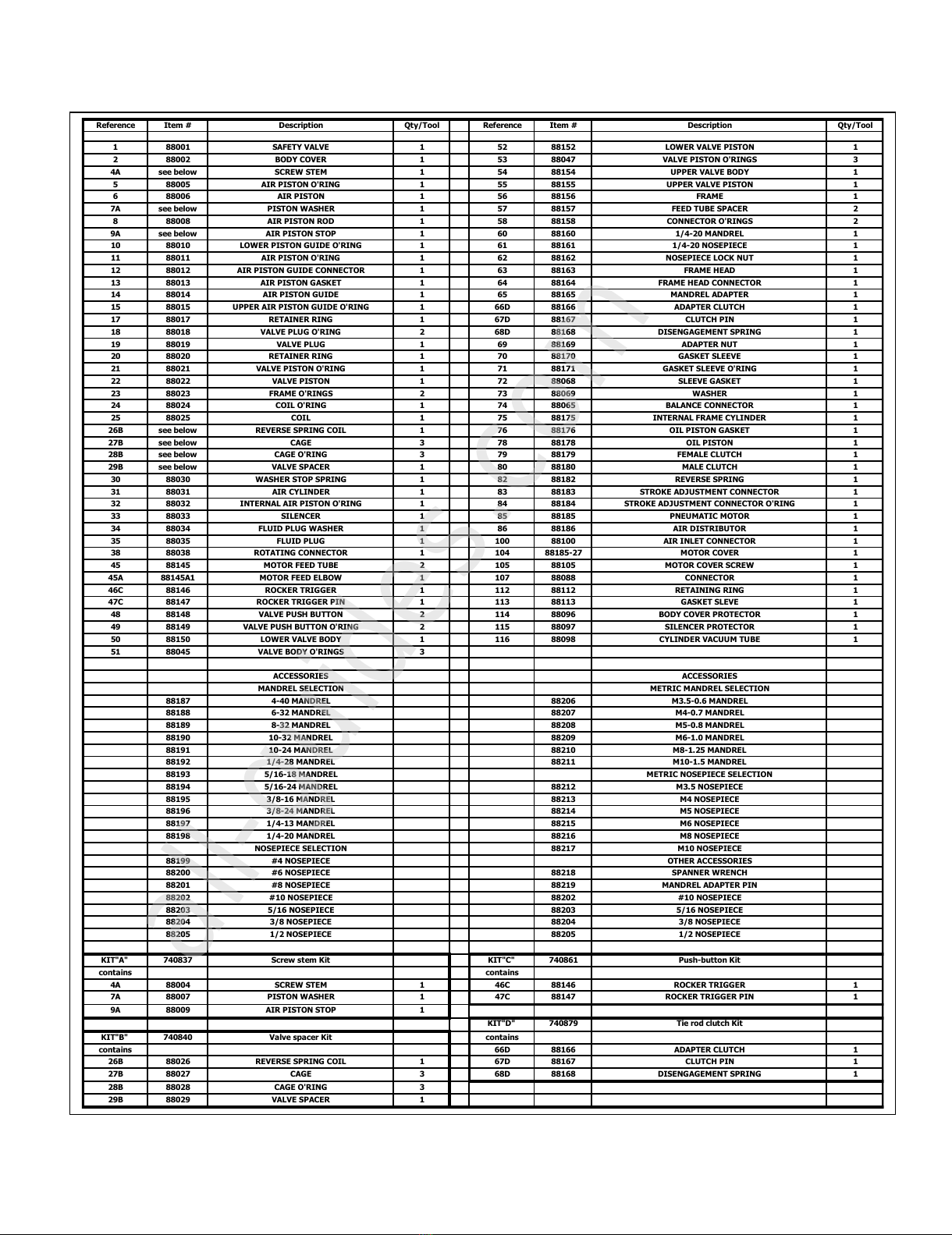
Reference Item # Description Qty/Tool Reference Item # Description Qty/Tool
188001 SAFETY VALVE 1 52 88152 LOWER VALVE PISTON 1
288002 BODY COVER 1 53 88047 VALVE PISTON O'RINGS 3
4A see below SCREW STEM 1 54 88154 UPPER VALVE BODY 1
588005 AIR PISTON O'RING 1 55 88155 UPPER VALVE PISTON 1
688006 AIR PISTON 1 56 88156 FRAME 1
7A see below PISTON WASHER 1 57 88157 FEED TUBE SPACER 2
888008 AIR PISTON ROD 1 58 88158 CONNECTOR O'RINGS 2
9A see below AIR PISTON STOP 1 60 88160 1/4-20 MANDREL 1
10 88010 LOWER PISTON GUIDE O'RING 1 61 88161 1/4-20 NOSEPIECE 1
11 88011 AIR PISTON O'RING 1 62 88162 NOSEPIECE LOCK NUT 1
12 88012 AIR PISTON GUIDE CONNECTOR 1 63 88163 FRAME HEAD 1
13 88013 AIR PISTON GASKET 1 64 88164 FRAME HEAD CONNECTOR 1
14 88014 AIR PISTON GUIDE 1 65 88165 MANDREL ADAPTER 1
15 88015 UPPER AIR PISTON GUIDE O'RING 1 66D 88166 ADAPTER CLUTCH 1
17 88017 RETAINER RING 1 67D 88167 CLUTCH PIN 1
18 88018 VALVE PLUG O'RING 2 68D 88168 DISENGAGEMENT SPRING 1
19 88019 VALVE PLUG 1 69 88169 ADAPTER NUT 1
20 88020 RETAINER RING 1 70 88170 GASKET SLEEVE 1
21 88021 VALVE PISTON O'RING 1 71 88171 GASKET SLEEVE O'RING 1
22 88022 VALVE PISTON 1 72 88068 SLEEVE GASKET 1
23 88023 FRAME O'RINGS 2 73 88069 WASHER 1
24 88024 COIL O'RING 1 74 88065 BALANCE CONNECTOR 1
25 88025 COIL 1 75 88175 INTERNAL FRAME CYLINDER 1
26B see below REVERSE SPRING COIL 1 76 88176 OIL PISTON GASKET 1
27B see below CAGE 3 78 88178 OIL PISTON 1
28B see below CAGE O'RING 3 79 88179 FEMALE CLUTCH 1
29B see below VALVE SPACER 1 80 88180 MALE CLUTCH 1
30 88030 WASHER STOP SPRING 1 82 88182 REVERSE SPRING 1
31 88031 AIR CYLINDER 1 83 88183 STROKE ADJUSTMENT CONNECTOR 1
32 88032 INTERNAL AIR PISTON O'RING 1 84 88184 STROKE ADJUSTMENT CONNECTOR O'RING 1
33 88033 SILENCER 1 85 88185 PNEUMATIC MOTOR 1
34 88034 FLUID PLUG WASHER 1 86 88186 AIR DISTRIBUTOR 1
35 88035 FLUID PLUG 1 100 88100 AIR INLET CONNECTOR 1
38 88038 ROTATING CONNECTOR 1 104 88185-27 MOTOR COVER 1
45 88145 MOTOR FEED TUBE 2 105 88105 MOTOR COVER SCREW 1
45A 88145A1 MOTOR FEED ELBOW 1 107 88088 CONNECTOR 1
46C 88146 ROCKER TRIGGER 1 112 88112 RETAINING RING 1
47C 88147 ROCKER TRIGGER PIN 1 113 88113 GASKET SLEVE 1
48 88148 VALVE PUSH BUTTON 2 114 88096 BODY COVER PROTECTOR 1
49 88149 VALVE PUSH BUTTON O'RING 2 115 88097 SILENCER PROTECTOR 1
50 88150 LOWER VALVE BODY 1 116 88098 CYLINDER VACUUM TUBE 1
51 88045 VALVE BODY O'RINGS 3
ACCESSORIES ACCESSORIES
MANDREL SELECTION METRIC MANDREL SELECTION
88187 4-40 MANDREL 88206 M3.5-0.6 MANDREL
88188 6-32 MANDREL 88207 M4-0.7 MANDREL
88189 8-32 MANDREL 88208 M5-0.8 MANDREL
88190 10-32 MANDREL 88209 M6-1.0 MANDREL
88191 10-24 MANDREL 88210 M8-1.25 MANDREL
88192 1/4-28 MANDREL 88211 M10-1.5 MANDREL
88193 5/16-18 MANDREL METRIC NOSEPIECE SELECTION
88194 5/16-24 MANDREL 88212 M3.5 NOSEPIECE
88195 3/8-16 MANDREL 88213 M4 NOSEPIECE
88196 3/8-24 MANDREL 88214 M5 NOSEPIECE
88197 1/4-13 MANDREL 88215 M6 NOSEPIECE
88198 1/4-20 MANDREL 88216 M8 NOSEPIECE
NOSEPIECE SELECTION 88217 M10 NOSEPIECE
88199 #4 NOSEPIECE OTHER ACCESSORIES
88200 #6 NOSEPIECE 88218 SPANNER WRENCH
88201 #8 NOSEPIECE 88219 MANDREL ADAPTER PIN
88202 #10 NOSEPIECE 88202 #10 NOSEPIECE
88203 5/16 NOSEPIECE 88203 5/16 NOSEPIECE
88204 3/8 NOSEPIECE 88204 3/8 NOSEPIECE
88205 1/2 NOSEPIECE 88205 1/2 NOSEPIECE
KIT"A" 740837 Screw stem Kit KIT"C" 740861 Push-button Kit
contains contains
4A 88004 SCREW STEM 1 46C 88146 ROCKER TRIGGER 1
7A 88007 PISTON WASHER 1 47C 88147 ROCKER TRIGGER PIN 1
9A 88009 AIR PISTON STOP 1
KIT"D" 740879 Tie rod clutch Kit
KIT"B" 740840 Valve spacer Kit contains
contains 66D 88166 ADAPTER CLUTCH 1
26B 88026 REVERSE SPRING COIL 1 67D 88167 CLUTCH PIN 1
27B 88027 CAGE 3 68D 88168 DISENGAGEMENT SPRING 1
28B 88028 CAGE O'RING 3
29B 88029 VALVE SPACER 1
All manuals and user guides at all-guides.com
all-guides.com
This manual suits for next models
1
Table of contents
Other Marson Tools manuals