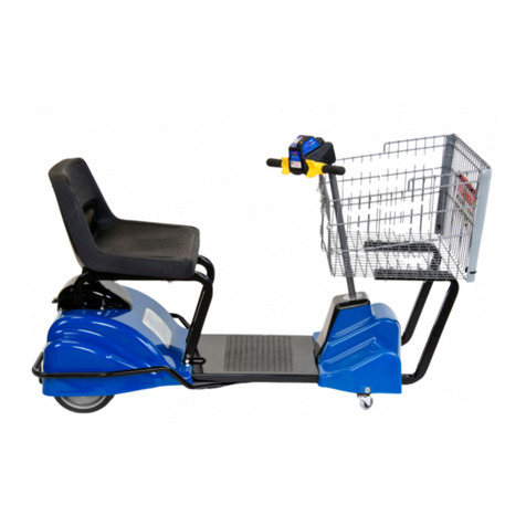
Mart Cart Commercial 02002 User manual

TM
OWNER'S MANUAL
MODEL #02002, ''Commercial Series''
CONGRATULATIONS!
You
have just purchased the best electric shopping cart on the market today, incorporating
the very latest in technological advances.
To
assure you of the best and safest performance
as well as longest equipment life, please read the enclosed information.
After reading the material in this manual, should you have a service problem
or
need help
please call our customer service department on our toll free number: 1-800-548-3373.
TO
ORDER
PARTS
CALL:
1-501-636-5776
or
1-800-548-3373
Be
sure
to
give
the
serial
number
to
the
parts
department
per-
sonnel.
This
number
is
located
on
the
rear
body
near
the
charging
cord
shown
at
upper
middle
of
exploded
view
drawing
,
page
6
in
this
manual.
TERMS:
All
parts
will
be
shipped
with
check
in
advance
or
C.O.D.
Commercial
accounts
are
allowed
30
day
terms
from
date
on
invoice
with
approved
credit
.
FREIGHT:
All
freight
will
be
paid
by
the
customer.
Special
consider-
ation
will
be
given
to
items
under
warranty
coverage.
MART
CART,™
115
E.
LINDEN,
ROGERS,
AR
72756
Form
#12889
OM, Rev.
8-91
Pr
inted in U.
S.
A.

TABLE
OF
CONTENTS
I.
WARNINGS. . . . . . . . . . . . . . . . . . . . . . . . . . . . . . . . . . . . . . . . 3
II.
RESTRICTION TO OPERATION . . . . . . . . . . . . . . . . . . . . . . . 3
III.
FREIGHT DAMAGE . . . . . . . . . . . . . . . . . . . . . . . . . . . . . . . . . 4
IV.
WARRANTY REGISTRATION . . . . . . . . . . . . . . . . . . . . . . . . . 4
V.
PREVENTATIVE MAINTENANCE . . . . . . . . . . . . . . . . . . . . . . 4
VI. BATTERY CHARGING . . . . . . . . . . . . . . . . . . . . . . . . . . . . . . . 4
VII.
TROUBLE
SHOOTING CHART . . . . . . . . . . . . . . . . . . . . . . . . 5
VIII. EXPLODED VIEW . . . . . . . . . . . . . . . . . . . . . . . . . . . . . . . . . . 6
IX.
PARTS LIST . . . . . . . . . . . . . . . . . . . . . . . . . . . . . . . . . . . . . . . 7
X.
PICTORIAL WIRING DIAGRAM . . . . . . . . . . . . . . . . . . . . . . . . 8
XI.
BATTERY REPLACEMENT . . . . . . . . . . . . . . . . . . . . . . . . . . . 8
XII. THROTTLE CABLE REPLACEMENT . . . . . . . . . . . . . . . . . 9-12
XIII.
SAFE-T-STOP . . . . . . . . . . . . . . . . . . . . . . . . . . . . . . . . . . . . . . 12
XIV.
SAFE.:r-STOP,
How It Works . . . . . . . . . . . . . . . . . . . . . . . . . . 12
XV.
SAFE.:r-STOP,
Wiring Diagram . . . . . . . . . . . . . . . . . . . . . . . . 13
XVI. DRIVE BELT . . . . . . . . . . . . . . . . . . . . . . . . . . . . . . . . . . . . . .
14
XVII. CIRCUIT BREAKER . . . . . . . . . . . . . . . . . . . . . . . . . . . . . . . . 14
XVIII. SEAT SWITCH. . . . . . . . . . . . . . . . . . . . . . . . . . . . . . . . . . . . .
14
XIX.
RELAY, CHARGING . . . . . . . . . . . . . . . . . . . . . . . . . . . . . . 14-15
XX. CORD REEL . . . . . . . . . . . . . . . . . . . . . . . . . . . . . . . . . . . . . .
15
XXI. RHEOSTAT -Variable Speed Control
.....
......
.
..
.
..
15
XXII. MOTOR MAINTENANCE . . . . . . . . . . . . . . . . . . . . . . . . . . . .
15
XXIII. FOOT BRAKE . . . . . . . . . . . . . . . . . . . . . . . . . . . . . . . . . . . . .
15
XXIV. TIRE &
WHEEL
REPAIR . . . . . . . . . . . . . . . . . . . . . . . . . . . .
16
XXV. SEAT ASSEMBLY -Maintenance . . . . . . . . . . . . . . . . . . . . . .
16
XXVI. CONTROL BOX
...
..
....
.......
...
.. ..
.
...
..
......
16
XXVII.
WARRANTY
..
. . .
....
. .
..
........
..
...
....
..
.
.....
16
-2
-

I.
PLEASE
READ
BEFORE
OPERATING
WARNINGS: I
A. Neverattempt to charge the battery in this cart without using an electrical outlet that is protected
by a GFCI, (Ground Fault Circuit Interrupter).
B.
Replace charging cord
or
cord reel
if
either is damaged or
if
the cord is worn
or
frayed.
C.
Never use the charging cord without proper grounding. Do not use
if
plug does not have three
terminals.
D.
Never allow the Mart Cart to
be
used out•Of•doors
or
on any surface that is not level.
E. Always disconnect power before servicing.
WARNING
LABELS
(RED)
ON
CART
&
WARNING
&
TO
PRE
VENT PERSONAL INJURY FROM
ELECT
RI
CAL SHOCK DO
NOT
USE IF:
1)
THE
ELECTRICAL OUTLET IS N
OT
PROTECTED
BY
A
GROU
ND FA
ULT
INTERRUPTER (GFI)
2)
THE
ELECTRICAL
COAD
OR
PLUG IS
DA
M
AGED
OR WO
RN
··
REPLACE BEFORE
USING
"A,B,C"
Above
I
USE
INDOORS
ON
LEVEL
SURFACE
ONLY
I
"D"
Above
D.
RESTRICTION TO OPERATION:
HIGH
VOLTAGE
Disconnect
power
before servicing
"E"
Above
A. This cart is for use indoors • on level surface
only
. (See decal
"D"
above.)
B. Standing on cart is permitted providing the operator stands in the center only. DO NOT STAND
WHILE CART IS MOVING. Be certain all switches are in the
"OFF"
position before standing. (See
"Operating Instructions" on Cart.)
C.
After battery is charged, disconnect power supply cord before operating Cart. (See decal
"C"
below.)
D.
Do not exceed the load limitations
as
shown on the Cart. (See decal
"D
" below.)
E. Do not force power supply cord into the rear housing
of
cart. Follow posted operating instructions.
(See decal
"E
" below.)
F.
Never leave battery on charger over
10
hours. (See page 4 tor recommended charging time.)
G.Neverfill pneumatictiresabovepressure rating shown on the sidewall
of
thetires. Foam.filled tires
do
not require
air,
and will exhibit "O" pounds
of
pressure on tire gauge.
H.DO NOTallowchildren to operatecart. Keep cart secured with key
at
service counter oroffer "Key
Club"
program. (Key Club program • form
#111789.)
RESTRICTION
LABELS
ON
CART
(BLACK)
ELECTRONIC SHUT-OFF
BATTERY
CHARGER
120
VOLTS-INPUT-1.9 AMPS
DISCONNECT
BEFORE OPERATING CART
"C"
Above
WARNING
:
FAILURE
TO
COMPLY
WITH
POITEO
OPERATINI
INmUCTIONS
AND
LOAD
LIMITATIONS
COULD
RESULT
IN
ACCIDENl
OR
INJURY
.
►--
LOAD
LIMITATIONS--
◄
MAXIMUM
PERSON
-
---
- 1
MAXIMUM
WEIGHT
IPeraon)
..
..............
..
..
.
..
300
LBS.
MAXIMUM
LOAD
IB11k11,,.__
___
75
LBS
.
NO
CHILDREN
ALLOWED
IN
BASKET
"D"
Above
-3-
Automatic
Rewind
Cord
Reel
OPERATING
INSTRUCTIONS
TO
REWIND
:
PULL
OUT
ON
CORD
UNTIL
LOCK
IN
G
DEV
I
CE
STOPS
"C
LICK
IN
G"
SO
U
ND
.
ALLOW
CORD
TO
SELF
RETRA
CT U
NDE
R
TENSION
.
CAUTION:
DO
NO
T
PUSH
CORD
INTO
HOLE
OR
DA
M
AGE
COU
LD
RESULT
.
"E"
Above

m.
FREIGHT DAMAGE:
CHECK: 1. The shipping carton for any visible damage. Report the damage to the freight carrier
immediately. File a claim with
the
carrier
if
actual damage to your cart has occurred.
2. Contents
of
the carton. The contents should agree with the information listed on the
packing list. Report any shortage to the carrier and the factory immediately.
IV
. WARRANTY REGISTRATION: I
1. Complete & return the
WARRANTY
REGISTRATION CARD. Noting the serial numberlocated near
the charging cord.
BEFORE OPERATING, READ ALL INSTRUCTIONS THOROUGHLY.
v. IPREVENTATIVE MAINTENANCE: I
VI
.
1.
Ifrequired, checktire pressure every6 months.Airtiresto30PSI
or
as printedon thetire sidewalls.
Most carts after November, 1990 are equipped with foam-filled tires, in which case only an
occa
-
sional inspection
of
tread wear is necessary.
2. Check cord reel daily for proper operation. Cord should retract fully into rear housing with only
the plug showing. Replace
if
faulty.
3. Check dailythe condition
of
the
power supply cord. Replace with new cord reel
if
worn
or
frayed.
4. Check dailythe operation
of
the
cart -all functions: key switch, forward-reverse switch, battery
condition meter, seat switch, safe-t-stop, chairlock &swivel, throttle, foot brake, etc. Repair
if
faulty.
5. Check daily the anti-tip castors (dwg. #23, fig.
1)
to be sure they are adjusted properly and are
in good condition.
6. Clean cart daily. Use "Appliance Magic" fiberglass & plastic cleaner for high luster.
NOTE: For
the
best preventative maintenance plan, and best CUSTOMER SERVICE, assign one
employee the daily task
of
cleaning and inspecting the cart(s). This way you will know who
is responsible for the cart(s) and there should be
no
excuse for customer dissatisfaction.
BATTERY CHARGING: I
1. Install a Ground-Fault Circuit Interrupter (GFCI) in store's electrical outlet wherever Mart Cart is
to be charged. This is to protect against any possible shock hazard. Installation
of
the GFCI must
be done by a licensed electrician.
2.
AC
voltageof the powersource required is 120
VAC
currentdraw
is
1.6 amps A.C. (output of charger
is 14.5 volts D.
C.
, 6 amps.)
3. Charge battery nightly after dailyusage. When battery is fully-charged, the charger will
ma
intain
a "trickle" charge to keep battery at its peak
or
shut
off
automatically depending
on
charger type.
We
recommend chargingtime not to exceed
10
hoursto achieve the maximum battery and charger
life.
To
accomplish thi
s,
a
110
volt
10
hour timer is recommended.
WARNING- 4. Do notcharge continuously, such as
dur
ing theday & night, as it's not necessaryand will reduce
the battery life. Daily excessive charging more than the
10
hours recommended could result in
severe damagetothe batteryand possiblythe charger. Always keepbatterycovered whilecharging.
5.
One complete charge
(14
hours
if
battery is completely without charge) will allow
up
to 3 days
of
normal grocery store operation.
6.
To
determine if chargerisworking
or
battery istaking a charge;
1)
Plugcord in to live wall socket, 2)
Turn key switch to "
ON"
position, 3) Place direction switch (FWD/REV switch) in "OFF" posi-
tion, 4) Rotate throttle grip to full "on" position. Needle should move from left to far-right side
of
battery condition meter. If the needle doesn't move, see "Trouble Shooting" Chart on page 5.
7. Maintenance
of
battery: none required as battery is a gel-eel design and requires
no
water.
Under normal circumstances, the Mart Cart battery should last 1½ to 3 years,
or
longe
r,
if
the above
recommendations are followed. Replace with
an
original gel-eel battery. Mart Cart™is not respon-
sible for any adverse effects caused
by
a replacement lead-acid battery.
-4
-

TO TEST BATTERY CONDITION: Read The Meter Under Load
To
test the battery, turn on the key switch, place rocker switch in forward, twist throttle grip fully-on.
To
get a true indication
of
battery level the cart must be running putting the battery under a load.
VII.
I TROUBLE SHOOTING: I
CAUTION: WALL SOCKET SHOULD HAVE GROUND
FAULT
INTERRUPTER
INSTALLED
BY
QUALIFIED ELECTRICIAN
TOOLS REQUIRED: screwdrivers-blade & phillips; socket set-7/,s,½,9/,s; box
or
open-end
wrenches-71,
6
,½,
9
/,
6; alien wrenches-%2
,1/a,%
2
,3/,
6; small crescentwrench; vice-grips; soldering gun,
flux & solder; electric drill & bits; wirecutters, strippers & crimpers (good quality); voltage-Ohm meter
with continuity checker; spray cleaner (Appliance Magic for countertops and plastics); clean rags;
LPS
#1
Lubricant, heavy duty grease.
PROBLEM
1.
Cart
moves
with
switch
in
"FWD"
or"
REV"
without
actuating
throttle
2.
Cart
stops
when
making
right
or
left
turns
3.
Cart
won't
go
at
all
,
throttle
sys
tem
O.K.
4.
Cart
won't
go,
throttle
system
O.K.
,
wiring
harness
O.K.
,
battery
weak
5.
Cart
goes
but
only
at
higher
speed
when
t
hrottle
is
at
or
near
full
"on"
6.
Battery
won't
take
a
charge.
Cart
quits
part
way
through
shopping,
after
charging
all
night
7.
Cart
goes,
but
only
at
low
speed
,
or
for
short
duration
with
above
conditions
ruled
out
B.
Cart
won't
go
,
or
moves
intermit-
tently
,
or
a
grinding
noise
orig
i
nates
from
motor
9.
Cart
won
't
go
or
operates
in
only
"
FWD"
or
only
"REV".
Above
condi
tions
ruled
out
10.
Battery
test
meter
won
't
operate
11.
Seat
won't
swivel,
rocks
back
&
forth
or
swivels
too
freely
PROBABLE CAUSE
1.
Broken
or
weak
throttle
spring
or
broken
cable
2.
Loose
set
screw
on
throttle
plate
3.
Improper
adjustment
of
throttle
cable
1.
Broken
wire
in
harnes
s
where
it
exits
steering
column
1.
Broken
wire
in
harness
2.
Weak
battery
3.
Defective
or
old
battery
4.
Open
c
ircuit
breaker
5.
Safe-T-Stop
faulty
6.
Seat
switch
not
depressed
1.
Loose
wire(s)
in
cord
reel
or
defective
contacts
2. L
oose
wire
in
contro
l
box
3.
Loose
wire
at
key
switch
4.
Battery
terminal
loose
5.
No
power
at
wall
socket
6.
Faulty
battery
charger
1.
Broken
or
cracked
wi
nd
i
ng
on
rheostat
2.
Throttle
spring
broken
1.
Defective
or
old
battery
2.
Defective
cha
rger
3.
See
4
(1)
above
4.
Defective
line
cord,
plug
5.
No
power
at
wall
socket
1.
Weak
battery
2.
Tire
rubbing
on
body
3.
Rheostat
wiper
arm
not
reaching
full
"ON"
position
4.
Drive
belt
loose
5.
Power
cord
wrapped
around
tire
6.
Defective
wheel
bearing
7.
Low
tire
pressure
(some
models)
1.
Mot
or
gear
broken
2.
Motor
brushes
worn
out
3.
Motor
bearing
worn
out
4.
Pulley
set
screws
loose
5.
Drive
belt
loose
1.
Defective
"F
WD/REV
"
sw
it
ch
2.
Safe+Stop
faulty
1.
Loose
wiring
2.
Low
battery
3.
Defective
switch
4.
Defective
meter
5.
Throttle
not
fully
actuated
6.
Key
switch
not
turned
on
1.
Worn
swivel
2.
Seat-lock
engaged
-
5-
SOWTION
1.
Replace
2.
Tighten
,
adjust
cable
3.
Adjust
per
instructions
1.
Replace
wi
th
harness
ki
t
1.
Rep
l
ace
w/
harness
kit
2.
Charge
3.
Replace
w/
new
battery
4.
Reset
circu
it
breaker
5.
Examine
&
repair
6.
Operator
must
be
fully
seated
1.
Replace
r
eel
if
necessary
2.
Tighten
/
reconne
ct
3.
Tigh
ten
I
reconnect
4.
Tighten
/
recon
n
ect
5.
Chec
k
for
110
vo
lts
6.
Replace
battery
c
ha
r
ger
1.
Replace
rheostat
2.
Repla
ce
1.
Replace
battery
2.
Needle
on
charger
shou
ld
move
when
plugg
ed in.
Test
volt
me
te
r.
3.
See
4 (1)
above
4.
Repla
ce
5.
Test
,
try
different
socke
t
1.
Charge
or
r
eplace
2.
Check
wheel
bearing
or
axle
alignment
3.
Ad
j
ust
throttle
plate
4.
Tigh
t
en
5.
Release
&
test
cord
6.
Replace
bearing
7.
Inflate
to
pressure
shown
on
side
wall
.
(NOTE
:
foam
-
filled
ti
res
will
read
"O
"
pounds
pressure)
1.
Rep
l
ace
gear
or
motor
assembly
2.
Replace
brushes
3.
Rep
l
ace
motor
asse
m
bly
4.
Tighten
set
screw
5.
Tighten
to
½"
to
¾"
deflection
1.
Rep
l
ace
2.
Examine
&
Repair
1.
Tighten
I
reconnect
2.
Charge
3.
Check
w /
cont
inuity
test
er
4.
Check
wi
th
volt
meter
5.
Twist
throttle
grip
to
full
position
speed
6.
Turn
key
switch
on
1.
Replace
swivel
or
entire
sea
t
assembly
2.
Move
&
hold
lo
ck
ing
l
eve
r
forward
,
rotate
seat

LO
DED
VIEW
EXP
-6-
REV. '
91
MODEL
SHOWN
DELUXE

~
~
-
.,..
~
~
~
--
--
=-
i
Li1n
~.~
--
-
-----
- 7 -
ca~
IX.
PARTS LIST
DRAWING PART
# #
1
2
3A
38
4A
48
6
7
BA
88
9
10
11
12
14
15
16
17
18
19
20A
2
08
21
22
23
24
25
26
27
28
29
30
31
32
33
34
35
36
37
38
39
40
41
42
43
44
45
46
47A
478
48
200-1316
200-8008
200-8005
200-8000
200
-1035
200-1354
200-1033
200
-1042R
200
-1117
200-1399
200
-
1119
200-1122
200-1120
000-1107
200
-1255
200
-1091
000-0030
000-1095
000-1341
200-1356
200-1334
200
-
1365
200
-
1006
200
-1108
200
-
1052
200-1330
200-1017
200-8015
200
-
1162
200-1154
200-1100
000-1256
200-9000
200-8030
200-8040
200-1016
200-1142
200-1346
200-1331
200-1129
200-1027
200-1298
200-1008
200-8025
200-9010
200-8050
200-8060
200-1265
200-1105
200-1401
200-12
77
200-4000
200-4001
200-8035
COMPONENT NAME
HAND GRIP FOR THROTTLE EXTENSION;
~,o~c~~~
~
•:r'.°
EXTENSION
GRIP
COMPLETE
',
GR
IP
USED
MAIN THROTTLE GRIP ASSEMBLY
DUAL
THROTTLE SUB-ASSY-
1991
BATTERY CONDITION
METER
BATTERY CONDITION
METER
(FLAT FACE)
FORWARD -
OFF
-REVERSE SWITCH
STANDARD
HAND
GRIP
PAD
FOR
ARM
REST
PAD FOR
ARM
REST
SEAT (ONLY)
SWIVEL PLATE, LOCKING
SEAT PAD
KEY FOR MOTOR /
PULLEY
SHAFT
RELAY,
12
voe
,CHASSIS
MOUNT
MOTOR
THROTTLE CABLE
THROTTLE SPRING
THROTTLE BRACKET
RHEOSTAT SPEED CONTROLLER
BATTERY CHARGER WITH 18
INCH
POWER
CORD
BATTER CHARGER WITH 6 FOOT POWER
CORD
BATTERY
BRAKE
PAD
ANTHIP
CASTOR
FRONT & LEFT REAR
WHEEL
&
TIRE
CIRCUIT BREAKER
FRONT CART TRIM, COMPLETE
LEFT
BASKET TUBE
RIGHT BASKET
TUBE
LARGE
GROMMET
METAL DRESS WASHER
BASKET WITH TRAY & TRIM
BASKET TRIM, COMPLETE
PRODUCE BASKET, COMPLETE
ELECTRICAL HARNESS, MAIN
KEY SWITCH
FLOOR MAT
DRIVE
WHEEL
W / 6" PULLEY
INSTRUCTION PLATE
BATTERY STRAP
V-BELT (USED W / #37 DRIVE WHEEL)
POWER
CORD
ASSEMBLY (NOT
ALL
MODELS)
REAR CART TRIM,
COMPLETE
SEAT ASSEMBLY, COMPLETE
FRONT FIBERGLASS COVER, COMPLETE
REAR FIBERGLASS COVER,
COMPLE
TE
BOO
T,
CORD REEL
2"
PULLEY
2½
" PULLEY
SEAT SWITCH
SET,
MAINTENANCE-FREE TIRES
SET,
PNEUMATIC TIRES &
WHEELS
, INCL.
(2) 200-1015 &
(1)
200
,1309
ARM
REST WITH P
ADS

'
X.
PICTORIAL WIRING DIAGRAM: AFTER 1990 :
u.
I
SR#24616 '
.
--~
• k ~c•
■
A1
0t
\
--
GM-ll
• Rf!l
ll-
·
O'll
•
WIIT(
tl~
•
uw:
l
•
WlT
( t
l\
·,•
">
PRIOR TO 1990 SR#24615
~I
=
:::.
i---------1
....
. -
..
....
..
. -
..
.....
- .
....
.
,---
--1--
,
I
I
I
<fl
~J
I
CN
L-
---
------------
--
------------1
,-----
f7---
l
a--l
~
. p
·~
11=11
1
k~ I
l
I
I
'"=-
--
~-
=-
-=-=-
=-
-
=-
-
=-
-=--
~ ~,---------
--
-------------J
--
--
FIGURE 2
/
/ , ~ ;
/
;;
-:-.LAY
DETAIL
/ -
TT
!
A
/:
i
REL
A
Y.
BA
T
TERY
,
& C
HA
RGER
WIRI
NG
AF
TEA
SERI
AL
NO.
27
27
0-0691
EF
F"
. D
ATE
6 · 2 4-9 1\
'-
'-..
---------
--✓
XI.
BATTERY REPLACEMENT:
I
I
I
To
replace the battery: (Read precautions on battery -avoid any sparks)
1. Shut off
key
switch and remove
key.
2.
Place forward-reverse switch in center
"off"
position.
FIGURE 3
3. Remove three screws thathold down rear cover. The one
in
front requires a screwdriver.The two
in the rear require a 7
/,
6"
box
wrench.
4.
Lift the rear cover straight up and offthe cart. Set on ground beside the cart being sure to pull
out sufficient power supply cord to allow enough slack for cover movement. DO
NOT
remove
power supply cord from cover unless cart is not equipped with a cord reel.
If
cart has no cord
reel (cord will not extract), push cord plug through grommet hole, then lift rear cover.
5. Disconnect the negative &positive wire bundles from the two battery posts &remove the battery.
6.
Install new battery w/ the negative
post(-)
towards the right rear ofthe cart -next
to
the drivewheel.
7. Connect the white and black leads
to
the negative post. Connect the blue &
red
leads to the
positive post.
8.
Secure battery with rubber strap or clamps. Check to be certain that the bundle
of
wires on
the right side of the battery (next to drive wheel) are not rubbing the drive wheel pulley.
9. Before re-installing cover -check tire pressure (if applicable -tires may be foam-filled
in
which case pressure will read
"0"),
wheel condition, belt tension and general condition of
other components.
10.
Re-install rear cover. Be certain cord reel power supply cord is free to work properly. Make
sure all three cover hold down screws are installed and tightened. (If without cord reel, place
cover
in
position & push the cord plug back through the grommet hole.)
11.
Test
cart for proper operation. Charge battery for 10 hours maximum.
IMPORTANT
Your
"Mart
Cart" has been equipped with a gel-eel battery during the manufac-
turing process as original equipment. The manufacturer recommends that you
replace the original battery only with the same type and rating to prevent pos-
sible damage to your cart's internal components, charging system,
or
personal
injury
to
you and your customer. (Mart Cart part number
1006
, item
21
, pg. 6.)
-8
-

XII. THROTTLE CABLE REPLACEMENT:
A. STEPS TO REPLACING THROTTLE CABLE:
1.
Shut
off
key switch
and
forward-reverse switch
2.
Turn to section VIII
"Exploded
View"
pages 6 &
7,
figure
1.
The
following parts will
be
considered:
DRAWING#
3
16
19
PART#
200-8005
000-0030
200-1356
COMPONENT NAME
MAIN THROTTLE
GRIP
ASSEMBLY
THROTTLE CABLE
RHEOSTAT
SPEED
CONTROLLER
3.
Begin by dis-assembling
the
clamps (part #6072, drawing
#2
, fig.
#4
below)
that
hold
the
main
throttle
grip
assembly
onto
the
steering handle bar. Notice that these
clamps
are
closest
to
the
black
control box mounted on
top
center
of
the
steeringcolumn.
DO
NOT remove
the
extension
arm clamps (part #1042, drawing #2 exploded view
page
6) unless this item needs replacement.
4. NOTICE that
the
main throttle
grip
clamp
(drawing #2, fig. #4) mounted on
the
top
of
the
steer-
ing
column fits
down
over two screw heads. These
heads
prevent
the
clamp
assembly
from
rotating around
the
crossbaron
the
steeringcolumn. Notice also
that
the
lower
half
of
the
clamp
has
the
throttle
cable
attached to it (drawing #3, figure 4 below)
FIGURE 4
Assembly
Co
mplete
AS VIEWED
FROM
FRONT
OF BASKET
EXTENSION ARM and THROTTLE GRIP ASSEMBLY
DRAWING#
2
3
4
5
6
7
9
PART
NO.
200-8005
200-1042A
200-1042C
200-1042D
200-1042E
200-1042F
000-0030
200-8008
DESCRIPTION
Throttle
grip
assembly with clamps (items 2 & 3).
Grip
(aluminum w/extension arm, nylon w/o extension arm),
casting & vinyl
grip
less
clamps
.
Clamp, throttle grip, upper. (set).
Clamp
, throttle
grip
, lower. (set).
Washer, lock. Throttle grip assembly.
Screw, throttle grip & ext. arm assembly.
Adjustment
screw
(part
of
cable assembly)
Cable, throttle assembly.
Arm, throttle extension w I
grip
.
-9-

XII
. THROTTLE CABLE REPLACEMENT Continued
5.
Slide the ball end of the throttle cable out of the take up spool on the end of the throttle grip.
(see
"arrow"
in figure 4, page
9).
6.
Remove the cable from the lower clamp by turning the adjustment screw (dwg.
#6,
figure 4)
counter-clockwise.
7.
Remove the rear cover of the Cart. See section
XI
"Battery Replacement" for instructions on
removing the rear cover, page 8.
8.
You
are now ready to pull the throttle cable through the front housing (dwg. #44, figure
1)
of the
cart. Notice the routing of the throttle cable as shown on the exploded view drawing, pages 6
&
7.
Start by feeding the cable down through the grommet in the front cover while pulling from
the bottom side. Notice that the cable passes through a restraining clamp on the left upperchasis
support near the base of the key switch. Pull the cable from front
to
back.
ITEM
PART
NO.
DESCRIPTION
1
200·1356
RHEOSTAT
2
NA
WIPER ARM, RHEOSTAT
3
000·1198
WASHER,
SPLIT
LOCK
If
10
4
000
·
1077
SCREW,
SOCKET
HEAD,
TEK
#
10•
\12
5
200
·
1340
PLATE.
RHEOSTAT
MOUNT
''-'G
6
000
-
1185
NUT
II
8 -
32
7
000
-
1198
WASHER, S
PLIT
LOCK
ti
10
8
000·1082
NUT,
',,
4
-20
9
000·1083
LOCK
WASHER, 1
'4
10
000
-
1234
WA
SHER, ,,.
ec:
s
11
000·1217
SET
SCREW,
SOCKET
ti
10
132 • 5
1s
12
NA
WASHER, RHEOSTAT ASSEMBLY
13
000-1185
NUT,
# 8 -
32
14
200
·
1095
THROTTLE
SPRING
15
000
-
1391
SCREW
, 118-
32
• 3
14
16
NA
NUT
, RHEOSTAT A
SSE
MBLY
ITEM
17
18
19
20
21
22
23
24
25
26
27
28
29
30
31
32
33
MART
CART
THROTTLE
SYSTEM
-
parallel
I
PART
NO.
DESCRIPTION
000·1366
THROTTLE
PLATE
000·6109
SET
SCREW,
THROTTLE
PLATE
COLLAR
000
·
1201
WASHER,
PLASTIC
000
-
0030
CABLE,
THROTTLE
ASSEMBLY
NA
NUT
,
THROTTLE
CABLE
NA
WASHER,
THROTTLE
CABLE
000·1234
WASHER,'
'•
USS
000
·
1144
SCREW,
SOCKET
HEAD
, 114 -
20
• 3
14
NA
WASHER.THROTTLE
CABLE
NA
NUT
,
THROTTLE
CABLE
NA
WIRE
,
THROTTLE
CABLE
NA
EYELET.THROTTLE
CABLE
000
·
1201
WASHER,
PLASTIC
000
·
1097
PIN,
CABLE
RETAINER,
%2
• 3
1/u
NA
DARK
BLUE
LEAD
TO
BATTERY
NA
DARK
BLUE
LEAD
TO
CONTROL
BOX
200
-
1341
BRACKE~THROTTLE
CA
BLE
Wiper arm adjustment (2). The wiper
arm
should rest on
the
"
OFF"
band when the throttle is released.
It
is permissible for the
wiper
arm
to
go
bey
ond the "
OFF
" band and rest on the ceramic portion of the rheostat. When
the
throttle
grip
is
twisted to
the
full
"O
N" position, the wiper arm should not cover more than ½
of
the
full
"ON"
band.
The
throttle plate
(17)
should
be
parallelto the rheostat mountingplate (5) when properlyadjusted. Alwayssecureset screw
(18)
and
other
fasteners. Checkcondi-
tion of
sp
ring
(14)
and
other
components when
se
rvi
c-;
ng.
-10 -

XII.
THROTTLE CABLE REPLACEMENT: Continued
9.
Notice the large gentle loop in the cable as
it
comes off of the rheostat (drawing
#19,
figure 1,
exploded view). When installing the new cable, you will want to maintain this loop. There should
not be any tight bends in the new cable when
it
is installed.
10.
Disconnect the cable from the throttle plate (drawing
#17,
figure 5) by pulling outthe hair pin re-
taining the cable (dwg.
#30,
figure 5). Save the washer and pin.
11.
Disconnect the cable from the cable mounting bracket (drawing #33, figure 5) by loosening the
nut closest to the throttle cable eyelet (drawing #26, figure 5) and drawing #28, figure 5). Notice
the position of the second nut (dwg.
#21,
figure 5) furthest away from the eyelet. This nut has
been turned up onto the adjusting screw (dwg. #20, fig. 5) to allow for proper cable adjustment
in relation to the wiper arm movement on the rheostat. When installing the new cable, set this
nut (dwg.
#21)
up onto the adjusting screw
on
the new cable in
the
same relative position as on
the old cable. Thiswill giveyou a good starting point from whichto make adjustments
if
necessary.
1
2.
Install the new cable. Begin at the back
of
the cart
by
feeding the cable eyelet (dwg. #28, fig.
5) through the hole in the throttle cable bracket (dwg. #33, fig.
5)
. Be certain that one nut and
one washer are on each side of the bracket as shown in figure 5.
13
. Tighten nut(#26) closestto the eyelet (#28) up against the bracket (#
33)
. Secure both nuts tight
against bracket. (Ref. figure 5
).
14.
Place eyelet (#28) over spindle
on
throttle plate (#
17
, fig.
5).
Be sure a washer (#
19
& 29) is posi-
tioned on top and bottom of eyelet. Insert pin (#30) to retain cable.
15.
Route the new cable through the retaining clamps from which
you
pulled the old cable through.
IMPORTANT: DO NOT kink cable atany time. DO NOT USE
if
cable has been kinked. All bends
should be gradual. The cable should move freely through the cable's housing when installed.
16. IMPORTANT: Be sure the newthrottlecable is secured out ofthe way ofthe front wheel assembly
when turning, clear of brake movement, and rear tire rotation.
17. Push the ball end of thecable upthrough thegrommetinthefront cover.
You
maywant to lubricate
the grommet
or
cable before pushing through. DO NOT remove the grommet to install the cable.
18
.
You
are now ready to connect the cable to the clamp that holds the throttle grip to the steering
column (drawing
#3,
figure
1)
. Feed the ball end
of
the cable through the clamp and screw in
the nylon adjusting screw until it
is
tight.
19
. Place the ball end ofthecable into the receptacle
on
the end ofthe throttle grip. Slide this assembly
onto the steering column. Place bearing grease onto the ball end and the bare cable. (
HINT:
To
get the ball into the throttle, it may
be
necessary to disconnect the throttle return spring (#14,
fig. 5). Be sure to
re
-connect later).
IMPORTANT: Always check the condition of the throttle grip (dwg.
#1
, fig. 4) for wear or cracks.
Replace
if
necessary.
20. Install top half ofthrottle gripclamp (dwg. #2, fig.
4)
. This clamp must
be
positioned directlyover
the 2 screw heads on the steering column crossbar. The throttle grip must be positioned inside
the two clamps so as to twist freely.
IMPORTANT: The throttle grip must stop rotating when it strikes a pin which has been inserted
into the upper clamp. The grip must not bind againstthis pin when twisted to the full "ON" posi-
tion. Also the extension arm assembly (dwg. #9, fig. 4) must rest parallel to the floor, facing the
basket, when in the "OFF" position. The exploded view drawing ofthe cart shows
the
extension
arm in the "OFF" position.(dwg.
#1
, fig.
1)
.
21
. Once you have the throttle grip assembly back together test for proper action. First, pull back
on the extension arm or twist the grip to the full "
ON
" position. The grip must stop against the
pin in the upperclampbefore the wiper arm on the rheostat reaches the stop built into therheostat.
If the throttle grip does not stop first
tw
o symptoms will appear:
1)
The cable will "strangle the
grip" causing the metal-ball-retaining-position of the grip to crack and break apart,
OR
2) The
force of the cable pulling
on
the rheostat wiper arm will crack and break the porcelain holding
the wiper arm.
22.
Turn
to figure 5 and be certain the wiper arm on the rheostat does two things:
1)
The wiper arm
must not touch the wires that create the "ON" position when the throttle grip is resting in
the
"OFF"
or
forward position. AND 2) The wiper arm must not
go
beyond half way onto the last
band of wire on the rheostat when in the fullest
"ON"
position.
-
11
-

XII. THROTTLE
CABLE
REPLACEMENT:
Continued
23.
You
can adjust wiper arm movement by adjusting the nuts(dwg.
#26
&
21,
figure 5)on the adjust-
ment screw (dwg. #20, figure
5)
on the end
of
the throttle cable OR you can make adjustments
by following the procedure shown at the bottom
of
figure 5.
24. Once you are certain
of
proper adjustments, you are ready to test the cart with power applied.
Turn on
key
switch, select "forward" or "reverse", and twistthe throttle grip slowly.The cart should
slowly move with an increase in speed with further advancement
of
the throttle.
XIII.
I
SAFE-T-STOP
I (Optional)
Another exclusive featurethat keeps the MART CART years ahead
of
the
competition.
SAFE-T-STOP
works in conjunction with MART CART's exclusive "Resilient Mounted Basket". When an object or
person bumps the leading edge of the basketthe cart instantly stops. Powerto the motor is instantly
cut off, stopping the continuous forward driving motion.
SAFE-T-STOP
works
so
well it is now offered as optional equipment on all models.
XIV. I
SAFE
-
T-STOP
How
It
Works
:
When the Sate.:r-Stop bumpertouches the basket, a circuit
is
closed causing thecartto stop. In order
for the cart to continue again,
the
operator
of
the cart must release the throttle grip allowing
it
to
go to the full "
OFF"
position. The cart will resume operating when the throttle grip is re-activated.
In order for the Safe-T-Stop to work, 4 components are required:
1)
Safe.:r-Stop Lever (Bumper), (2)
Microswitch
or
Mercuryswitch, (3) SCR (Silicone rectifier), and (4) a relay. Thesework in conjunction
with each other to make up the Safe.:r-Stop system.
This system is energized by a lead wire from the
"positive"
battery post
to
the
microswitch
or
mer-
cury switch. The mercury switch rests in a "normally open" position. When the throttle on the cart
is
advanced, the microswitch rotates(or mercury switch tilts),closingthecircuittothe SCR. The SCR
now waits in a stand-by mode for another signal (i.e., the closing
of
the external circuit: the bumper
lever hitting thebasket) before itclosesan internal circuitgoing to the relay.When the bumper strikes
the basket momentarily,the SCR passes power onto the relay. The relayiswired in a
"normally
clos-
ed"
position. When energized by the SCR, the coil
of
the relay holds the contacts
of
the relay in
an
"open" position until the SCR is de-energized. The relay interrupts power to one
of
the motor
leads. Thus, when the relay is energized by the SCR, the motor will not run. When the SCR is
no
longerenergized, the motor relay contacts will once again close completing the motor circuit. In order
for the SCR to be de-energized, the microswitch
or
mercuryswitch must return to its "normally open"
or
resting position. This is accomplished when the operator
of
the cartreleases the throttle.The mer-
cury switch is mounted on the spring loaded throttle plate which rotates when the throttle is twisted
at
the hand grip
or
released.
Trouble shooting the Safe-T-Stop system can be quite simple. If the cart won't run, bypass the SCR
activated relay.
To
dothis, simplyjoin the positive motorlead wiretogetherwith a jumperwire across
the two relay terminals where the two lead wires are attached. In so doing, you have by-passed the
system entirely. Now, if the cart won't run your problem
is
not with the Safe-T-Stop system.
You
will
have to trouble shoot the problem like any other cart that won't run.
Should the cart begin
to
function, however; then the problem rests with the Safe.:r-Stop system. Even
though the system can be easily by-passed as mentioned above
or
by disconnecting the positive
lead wire to the microswitch (or mercuryswitch), it is recommended that you trouble shootthe cause
of
failure and repair.
If the cart won't run with the Safe-T-Stop system connected, there are three places to look:
1. Short in external circuit
2. Defective relay
3. Defective SCR
Ifthe Bumperlever is touching any part of the basket
or
thewire lead goingtothe Bumper is touching
the basket
or
shorting against the frame, a false signal will be sent to the SCR causing
it
to energize
the relay.
If
the relay does not reset itself to a " normally closed" position, then it must be replaced.
To
test
the relay, simplydisconnect the leadwire from the SCR. Use a continuitytester acrossthe "normally
closed" terminals (the onesto which the motor leads should be attached). There should be continui-
ty across these terminals when the relay is non-energized.
- 12 -

XIV.
xv.
K>TOR
SAFE-T-STOP How It Works: Continued
To
test
the
SCR, there should
be
no
continuity across
the
center leg
of
the
SCR
and
the
leg with
the
lead going
to
the relay coil
when
power
to
the
SCR from
the
microswitch (or mercury switch)
has
been disconnected. It
is
important that
the
mercury in the switch does
not
make contact with
its internal terminals
when
the
switch
is
in a resting position (throttle closed).
Due
to
the
high
rate
of
reliability
of
SCR'
s,
microswitches(or mercuryswitches), and relays, it is likely
that
mostproblemsencountered will be associated with dailyabuse
of
the
bumper
or
possiblejarring
andmis-alignment
of
the mercuryswitch. Replacementmicroswitches(ormercuryswitches) and SCR's
will
be
provided with pre-soldered leads and insulators for easy replacement.
CAUTION:
The
SCA
is
a "positive
D.C.
operative" circuit. NEVER
APPLY
ANY NEGATIVE
CURRENT TO THE SCA OR COMPONENT WILL BE DESTROYED!
Do
not by-pass resistor to SCA or component failure may result!
SAFE-T-STOP
Wiring
Diagram
:
0
SCR
(rn-220>
LEVER
DPST
RELAY
(N/C)
h~
RESISTOR
FIGURE 6
JI
BASKET
rFTI
FRAME(+)
CIRCUIT
<l--
--'
XVI.
(-)
BATTERY
DRIVE BELT I
SPOT
MICROSWITCH
........
~NO
NC
(+)
BATTERY
ELECTRICAL CIRCUIT SAFE-T-STOP
NOTE: SCA
PIN 1 = CATHODE
PIN 2 = ANODE
PIN 3 = GATE
1.
The
drive belt is shown in
the
exploded view drawing
on
page
6.
See
drawing #40. On account
of
the
slow
speed
at
which the motor
turns
and
due
to
the
heft
of
the
belt
used,
your
belt
should
never require replacement. For this reason Mart
Cart
offers a lifetime limited parts warranty on
the drive belt.
2. Proper belt tension will extend
the
life
of
the
drive system components.
The
dr
i
ve
belt
is
installed
by
the
factory using
20
ft. lbs.
of
torque. This results in a
belt
that when pressed in
the
center
will deflect approximately
½"
to
¾". ·
3.
Proper
belt
tensionwill reduce
belt
wear, increase drivewheel bearing life, reduce drive train shock
when the
cart
isswitched from
"forward"
to
"reverse"
or
viseversa, and increase motor
gear
and
bearing life.
-13-

XVI.
XVII.
DRIVE
BELT
Continued
4.
To
adjust
belt
tension:
-
Shut
off
power, remove
key.
-Remove rear cover (see section XI). Keep fingers clear
of
belt & pulleys!
-Locate and loosen the two motor mounting plate bolts which pass through
the
frame.
-Pry upwards on
the
motor plate until belt is tight
(½"
deflection).
-Test cartbydriving in forward and reverse. A small amount
of
slippage is desirablewhen making
rapid changes
in
direction.
The
belt should not be
so
tight
as
to cause
the
cart to
jerk
when
switching rapidly from forward to reverse
or
vice-versa. On
the
otherhand, the belt should
not
be
so
loose as
to
not allow
the
cart
to
move when fully loaded.
CIRCUIT BREAKER I
1.
The
circuit breaker is designed
to
protect yourelectrical system from transient overloads
or
elec-
trical shorts. Either could cause serious damage without a circuit breaker to open
the
circuit.
2. MartCarts manufacturedafterJanuary
1,
1990 have
the
circuit breakermounted under
the
control
boxcover
on
top of the steering column. It isa "
manual"
type breakerrated at 15amps. It requires
resetting
once
it has been activated. Itwill not reset itselfautomatically for safety reasons.
To
reset
the breaker insert a pen
or
pencil point into the circuit breaker access hole on the front left
of
the
control box cover. Press inward
on
the
circuit breaker button until a "clicking" sound is heard.
The cart should now
be
ready to operate providing
the
cause for the circuit breaker tripping
was
not serious enough
to
trip
the
breaker a second
time
.
3. Mart Carts manufactured before 1990 have their circuit breaker mounted
under
the front cover
as shown in
the
exploded view drawing
on
page 6.
4. Some
of
the most common causes for the circuit breaker
to
open are:
1)
Low tire pressure
2) Worn wheel bearings which cause...
3) Tires rubbing body
of
cart
4) Short in "forward-off-reverse" switch
5) Shortin wiring harness-usually located
at
base of steering column on carts manufactured
prior
to
1986.
6) Activating throttle while pressing brake pedal.
X
VIII.
SEAT SWITCH I(Standard on deluxe model)
XIX.
1.
The
seat switch is a standard feature on all deluxe mart carts and optional
on
other models.
2. The seatswitch consists
of
a plate and rod assembly mounted underthe chairs seat pad. Pressure
downwards
on
the seat pad causes the rod to depress a spring-steel plate which rests on top
of
a 60
amp
rated push button switch. This switch closes the circuit to the motor. The cart will
not
operate
if
this switch is not depressed.
3.
Seat switch adjustments can be made by putting pressure upwards
or
downwards on the switch
support bracket located under the rear cover. NOTE: Foreign objects between seat pad
and
chair
may prevent the plunger rod from operating properly.
RELAY, CHARGING I(Standard on any models with cord reel)
1. Thisrelayis located underthe rear cover. It is mountedto the frame
of
the cartclosest totherheostat
or
furthest from the drive wheel, (see exploded view, drawing #14, page
7)
.
2. The relay is wired in the
"normally
closed" position. When the coil of the relay is energized
the
relay contacts
"open"
the motor circuit.
This
is to preventthe motor from operati
ng
while the bat-
tery
is
being charged. This will also prevent potential damage
to
your charging system -cord,
cord reel, charger, and electrical outlet.
3.
HOWIT WORKS: When
the
powersupplycord is plugged into
the
store's electrical outlet
the
bat-
tery charger is energized. The charger sends approximately 14.5 volts
to
the battery for charging.
Along the way
the
coil
of
the
charging relay is also energized. It will remain energized until
the
power
to
the
charger is disconnected. The motor circuit is interrupted until charging is complete.
When the charger
is
unplugged
the
motor circuit through the relay will be "
closed"
again.
-
14
-

XIX.
xx
.
XXI.
XXII.
:xxm.
RELAY,
CHARGING Continued
4.
You
can tell if the relay
is
working properly if you hear a distinct "clicking" sound coming from
the relay when you plug in the powersupply cord. Also, the cart should notoperatewhile charging.
CORD
REEL
I (Standard
on
deluxe model, Optional on all others)
1. The cord reel has been provided to save you hundreds
of
man hours in trying to find an extension
cord tocharge yourcarton a daily basis. Itwill alsokeepthe cord stored in a safe, protected place,
out
of
sight, where customers can neither see
it
or
trip over it.
2. The cord reel will give you years
of
trouble-free service providing thesimple operating instructions
posted on the cart are followed. (See "Operating Instructions" on page 3).
3. Most cord reel failures are due to abuse such as tugging on the cord to pull the cart plug,
or
by
not letting the reel retract the cord and the operator shoves the cord into the cart's rear housing.
The cord gets tangled around the rear wheel which in turn pulls on the cord and damages the
reel. Although a rubber boot has been installed between the cart housing and the cord reel to
prevent the cord from being shoved in, a heavy handed operator may try to push the cord past
the boot.
4. Always inspect the condition
of
the power supply cord on a daily basis. Replace
the
reel
if
the
cord
or
plug is damaged or if reel does not function properly.
IMPORTANT:
Aground fault circuit interrupter (GFCI) should be used in your store's electrical outlet
where you intend to draw current to charge your cart.
VARIABLE
SPEED
CONTROL I
1. The cart's speed is regulated by a heavy duty rheostat. This device provides extremely smooth
acceleration from
Oto
1.3 MPH.
2. The rheostat is located nearesttheleft rearwheel and slightlyabove,(see theexploded view, drawing
#19
, page 7).
3.
Although rheostat failures are very uncommon, the majori
ty
have been due to improper throttle
cable installation. In most instances the wiper arm on the rheostat has not been allowed to retract
off
of
the last band
of
energized wire. The rheostat then overheats and, like a fuse, quits working.
In some instances, the throttle cable allowed the operator to pull the wiper arm too far causing
the arm to strain against a built-in stopping mechanism. This mechanism will break
if
too much
strain is placed on it. See section XII for proper throttle cable replacement.
MOTOR
MAINTENANCE I
1.
There is no scheduled maintenancerequired. However, whenthe rear cover
of
the cart
is
removed
for other reasons (such as to replace the battery) the motor should be examined.
2. Whatto look for -checkthe belttension (see section XVI), check for any motor shaft seal leakage,
check the motor mounts, check the brushes
at
least once every 5 years.
3.
Motor brushes -there are two brushes
at
the rear end
of
the motor, one on top and one on the
bottom. They are each located inside a small round plastic housing. A small screwdriver may be
used to back outeach brush.
If
your motor stops running, worn brushes could be the cause. Due
tothe fact that your motor hasexternal brushes theywill outlast internal brusheswhich are smaller
and they are easier
to
replace.
FOOT
BRAKE
I
1.
The foot brake does not require any scheduled maintenance.
2. In order for the brake to offer maximum efficiency the left rear tire should be filled with air (if not
foam-filled) to its maximum rating. Also, the rear wheel bearings should be checked and replaced
if
excessive play is found.
-15-

XXIV.
XXV.
XXVI.
XXVII.
TIRE AND WHEEL REPAIR (For proper pressures
of
pneumatic tires see section
V.)
1. The large
10"
tires will provide many years
of
long tread wear before requiring replacement. The
tires should be replaced when the tread is worn off
or
if
there are signs
of
aging such as peeling
of
the tread
or
cracking
of
the side walls.
2. Foam-filled tires require no air, therefore the only maintenance is described in
(1)
above. They are
distinguished from pneumatic tires
by
a "O" pounds pressure reading when checked with an
air
gauge. On models with pneumatic tires, flats usually result from failure to keep the tires inflated,
a puncture
of
the tire,
or
a leaky valve stem.
3.
Tire and wheel removal has been made easy as the axles are equipped with snap rings.
4. Pneumatic tires are equipped with an inner tube. Most lawn mower dealers have repair facilities
that handle the inner tubes and flat repair work at a nominal fee.
"Fix
A Flat™" works well to
seal a puncture and inflate the tire without having to remove the wheel.
SEAT ASSEMBLY: I
1.
The seatassemblymayconsist
of
the following items all
of
which are replaceable:the chair, tubular
arm rest, plastic arm rest pads, seat cushion, and chair swivel plate.
2. The swivel plateshould be lubricated with grease
at
least once a
year.
It should also be examined
forexcessive play. Itshould be replaced when the chair rocks back and forth on the plate or when
the chair swivels too freely.
3.
Seat-lock should be inspected dailyfor properfunction. The release/locking arm should move for-
ward freely, and spring back into one
of
four locking positions. If return spring is broken,
DO NOT USE cart until spring is replaced.
CONTROL BOX I
1. The mastercontrol box islocated ontop
of
the steering column.Itcontainsthe "forward-off-reverse"
switch, the battery condition meter, and when ordered the horn and horn switch. Underthe cover
is the circuit breaker (units manufactured after January
1,
1990).
2. The cover can be removed by removing
the
two side screws. All components can be replaced
if
necessary.
WARRANTY I
A. PARTS: 1 Year Limited Warranty from date
of
shipment.
B.
BATTERY:
Full Warranty first 9 Months from date
of
shipment.
C. LABOR: 1 Year Limited Warranty
A. PARTS -Limited Warranty
All parts, except battery (See
B.
Battery below) flat tires (when applicable to some models), and
circuit breaker needing resetting, are warranted by the manufacturer
to
be free from defects in
material and work-manship for a period
of
1 year from date
of
shipment. This warranty does not
include wear and tear caused by above -normal usage, abuse, negligence, freight damage,
or
damage caused by improper use or care,
or
by outside sources such as fire, floods, etc.
Should anycomponentfail (except those mentioned) during the first year
of
ownership, return com-
ponent in question to the manufacturer
or
authorized representative for inspection.
If
component
hasfailed dueto defect in material
or
workmanship, itwill be exchanged or repaired at the manufac-
turer's discretion at no charge to the owner.
B.
BATTERY
The battery is fully warranted
up
to and including the first 9 months from date
of
shipment, and
prorated based on the net price
of
the battery
10
through
12
months from the date
of
shipment.
C. LABOR
The manufacturer will cover labor charges for work performed in the field for one full year from
thedate
of
shipmentas a result
of
defectin materials and workmanship. Charges incurred for reset-
tingthe circuitbreakerare exempted. Double servicecalls due to improperfirst-call service
or
lack
of
repair parts are exempted.
The above warranties exclude shipping, handling,
or
travel expenses incurred for
the
repair
of
said cart
or
parts as well as items worn out through normal use whose malfunction is
not attributable to defect.
Mart Cart, Inc.
115
E. Linden, Rogers, AR 72756
800-548-3373
501-636-5776
Table of contents
Other Mart Cart Mobility Aid manuals
Popular Mobility Aid manuals by other brands

Enabling Devices
Enabling Devices Ultimate Switch user guide

Decon wheel
Decon wheel MED3170 Assembly instructions

Harmar Mobility
Harmar Mobility AL003 Installation and owner's manual

aidapt
aidapt VP119 Fixing and maintenance instructions

Invacare
Invacare DOLOMITE Jazz Series user manual

Golden Technologies
Golden Technologies Companion I owner's manual