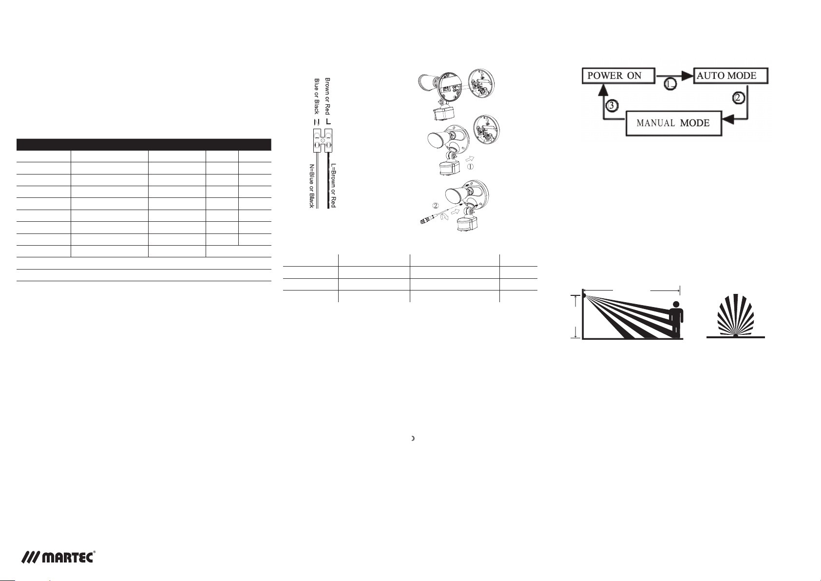
Defender Tricolour COB LED Security Light CCT:3000k,4000k,5000k
Model No. Description Tri Colour CCT IP Rating Warranty
MLDXD3451M Single Spot 3000k, 4000k 5000k IP54 2yrs
MLXD3451W Single Spot 3000k, 4000k 5000k IP54 2yrs
MLXLD3452M Double Spot 3000k, 4000k 5000k IP54 2yrs
MLXD3452W Double Spot 3000k, 4000k 5000k IP54 2yrs
MLXD3451MS Single Spot with sensor 3000k, 4000k 5000k IP54 2yrs
MLXD3451WS Single Spot with sensor 3000k, 4000k 5000k IP54 2yrs
MLXD3452MS Double Spot with sensor 3000k, 4000k 5000k IP54 2yrs
MLXD3452WS Double Spot with sensor 3000k, 4000k 5000k IP54 2yrs
LUMENS OUTPUT 3000k=1800Lms 4000k=2000Lms 5000k = 2000Lms
LED Powered by Bridgelux COB 10Watt Per Head
Voltage: 220-240VAC-50/60Hz
Martec Pty Ltd 6 Austool Place Ingleburn,NSW2565
P: 02 8778 7500 F: 02 8778 7555
DEFENDER Tricolour LED COB
Security Light with CCT With & Without Sensor
INTRODUCTION
Congratulations on purchasing your Martec high quality outdoor light fitting.
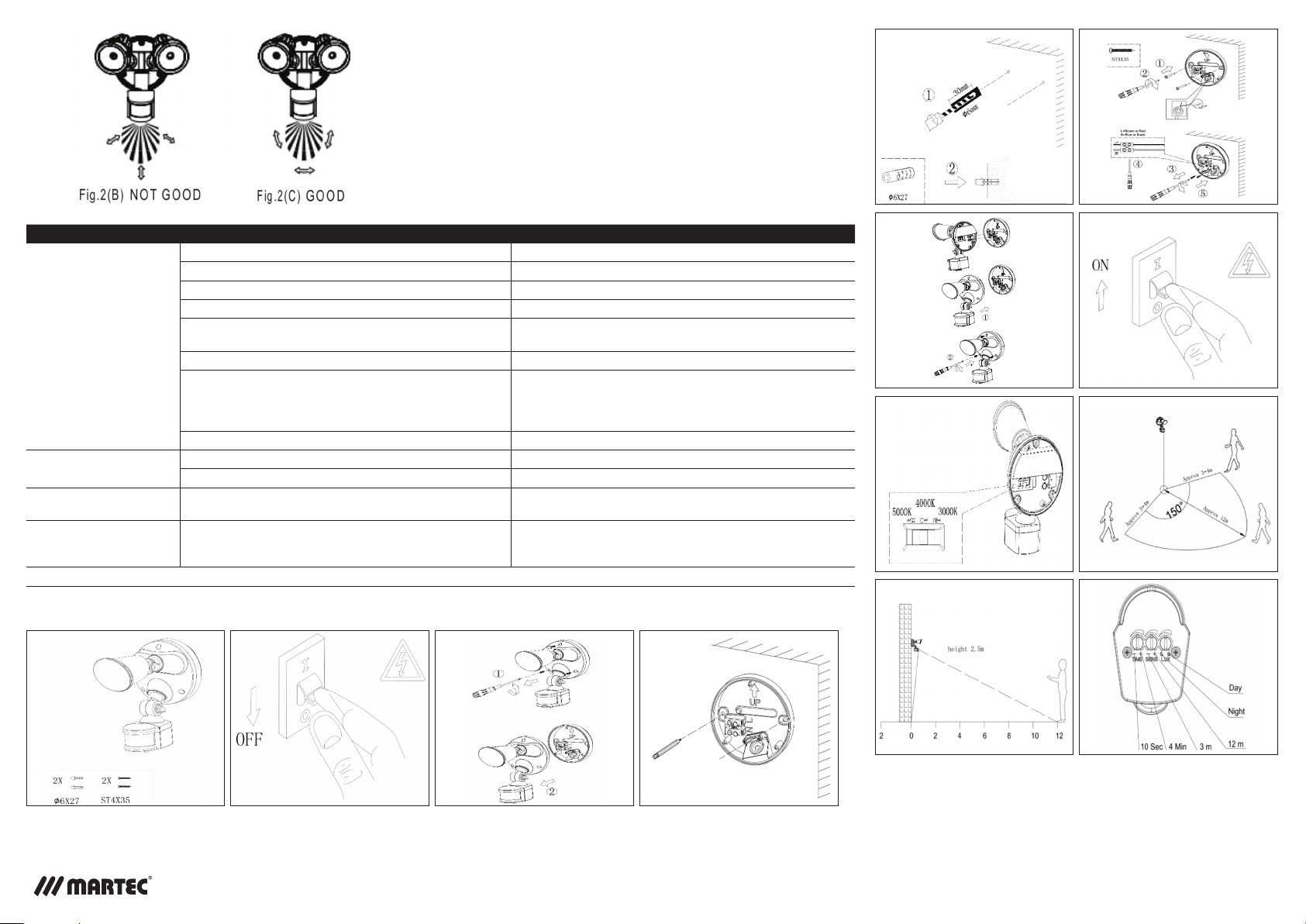
For installation of your Defender CCT Tricolour outdoor LED spotlight, please refer
to the Fig.1
1. Installation must be carried out by a licensed electrician and according to AS/
NZS 3000 and relevant amendments or warranty will be voided.
2. Switch power off at the meter box and ensure that there is no power to the
lamp.
3. Unscrew the Front Cover Screws and then separate the light from the back
plate.
4. Use the back plate to mark the position of the screw holes onto your mounting
surface. Drill the wall to a depth of about 40mm and fit the wall plugs (supplied).
Take care to avoid drilling or screwing into concealed electrical wiring.
5. Connect the Power Cable to the Terminal Block, see Fig.1, and ensure the cable
is drilled through the Rubber Gasket (supplied) to maintain the fittings IP rating.
6. Affix the back plate to the mounting surface with the Mounting Wall Screws
(supplied) once again using the Rubber Gasket (supplied) to maintain the fittings
IP rating.
7. Re-fit the light fitting to the back plate mounted on the wall.
Note:
Loosen knob on adjustable arm before making any adjustments to the direction
and position of the light heads.
OPERATING THE PASSIVE INFRARED SENSOR
MLXD3451WS Single spot sensor 3000k, 4000k, 5000k IP54
MLXD3451MS Single spot sensor 3000k, 4000k, 5000k IP54
MLXD3452MS Double spot sensor 3000k, 4000k, 5000k IP54
MLXD3452MS Double spot sensor 3000k, 4000k, 5000k IP54
When power is switched on to the Defender Sensor, it will enter into a “WARM-
UP” period for approximately 50 seconds (within 1 minute) and then automatically
change into “AUTO MODE”. Whilst in the AUTO MODE, you can then carry out a
Walk-Test by placing the LUX control to day position (.) and the TIME control to
minimum (-). Once the sensor receives a valid trigger signal (such as movement
of a human body) within its set distance detection area, the lamp(s) (load) will be
turned on for the pre-set period of time.
You will be able to determine the detection area by walking slowly.
After completing the walk-test, set the LUX KNOB to the night position to ensure
the sensor only operates at night and set TIME KNOB to the desired “ON’ time.
ADJUSTING THE LUX CONTROL LEVEL:
The Lux control module has a built-in sensing device (CdS photocell) that detects
daylight and darkness. (•) position denotes that the lamp(s) (load) will be turned
on by the PIR during both day and night. ( )position denotes that the lamp(s)
(load) will be turned on by the PIR only at night.
You can set to operate the unit at the desired level by adjusting the Lux Knob.
ADJUSTING THE DURATION TIME:
The duration time is “the length of time that the sensor switches the load ‘on’
after activation”. The duration time can be adjusted from (10±5) seconds to
(4±1) adjustable minutes.Rotating the TIME knob from (+) to (-) will reduce the
duration time.
Note: Once the lamp(s) (load) has been triggered by the PIR sensor any
subsequent detection will start the timed period again from the beginning.
How to change into MANUAL CONTROL MODE
1. When the power is on, the PIR detector enters into the “WARM-UP” period for
about 1 minute, then automatically changes into AUTO MODE.
2. During AUTO MODE, by switching the ON/OFF main switch 2 times within 3
seconds and then leaving the switch on, the PIR detector will automatically
change into MANUAL MODE from AUTO MODE. In MANUAL MODE, the
Lamp(s) will remain ON, in MANUAL MODE the PIR detector will not be
affected by duration time and Lux control level.
3. During MANUAL MODE, by switching the ON/OFF main switch 2 times within 3
seconds then leaving the switch on, the PIR detector will automatically change
into AUTO MODE from MANUAL MODE.
4. During MANUAL MODE or AUTO MODE, by switching off the ON/OFF main
switch over 10 seconds and then on again, the PIR detector will reset to
WARM-UP periods.
Please note: the period of “WARM-UP” maybe be shorter than 1 minute.
a. The security lamp should be wired to its own light switch only. No two way
switching.
Do not interconnect with other lights on the same switch. Earth connection is
be required.
b. Ideally the security lamp should be mounted 1.8 to 2.5m (6 to 8ft) above the
ground to be scanned (refer Fig.2A).
c. To avoid damage to the sensor unit- DO NOT aim the sensor towards the sun or
the photo electric cell will be damaged
d. To avoid nuisance triggering, the sensor should be directed away from heat
sources such as barbecues, Air-conditioners, other outside lighting, moving
cars and flue vents.
e. To avoid nuisance triggering, keeping away from areas of strong
electromagnetic disturbance.
INSTALLATION
please read carefully
Quick Connection System
Easy Installation)
max. 12m
2.5m
Max. distance approx. 12m 150° detection angle
Fig.2 (A) DETECTION AREA