Masibus MC-1-DE User manual

OPERATOR’S MANUAL
GPS Time Sync Unit
Masibus Automation And Instrumentation Pvt. Ltd.
B/30, GIDC Electronics Estate,
Sector-25, Gandhinagar-382044, Gu arat, India
+91 79 23287275-79
+91 79 23287281-82
Email: support@masibus.com
Web: www.masibus.com

Model: MC-1-DE
Doc Ref. No:-m05dom102
Issue No:-00
User’s Manual
Page 2 of 76
CONTENTS
1. INTRODUCTION ................................................................................................................................. 5
Foreword ............................................................................................................... 5
Notice ................................................................................................................... 6
Limited Warranty .................................................................................................... 6
Trademarks ............................................................................................................ 7
Product Ordering Code ............................................................................................ 7
2. Unpa king the MC-1-DE .................................................................................................................. 8
2.1 Packing List ......................................................................................................
3. GPS Fundamentals ............................................................................................................................ 9
4. MC-1-DE Spe ifi ation ................................................................................................................... 11
5. Unit Front Panel Des ription ...................................................................................................... 15
5.1 GPS TIME SYNC UNIT MC-1-DE Front Panel ........................................................ 15
6. GPS TIME SYNC UNIT MC-1-DE Installation ........................................................................... 19
6.1 GPS Antenna and Cable Information .................................................................. 20
6.2 Unit Installation .............................................................................................. 25
6.3 Mechanical Dimensions .................................................................................... 26
6.4 Wiring Diagram ............................................................................................... 27
7. GPS TIME SYNC UNIT MC-1-DE Power ON .............................................................................. 28
7.1 Receiver Boot-up mode .................................................................................... 2
7.2 Battery Backup RTC and GPS receiver RAM Configurations: .................................. 29
7.3 Startup Operation............................................................................................ 29
7.4 Basic Normal Run Mode Operation ..................................................................... 30
8. Serial Communi ation and Configuration .............................................................................. 31
.1 Serial Port Setup and Serial Cable Configuration ................................................. 31
.2 Configuration Commands ................................................................................. 34
9. Timing Outputs – Serial, IRIG-B, NTP ....................................................................................... 47
9.1 Timing Output – Serial ..................................................................................... 47
9.2 Timing Output – IRIG-B ................................................................................... 49
9.3 Timing Output – NTP ....................................................................................... 53
9.4 GPS Time Sync Unit NTP Output: ...................................................................... 54
9.5 NTP Client Synchronization: .............................................................................. 55

Model: MC-1-DE
Doc Ref. No:-m05dom102
Issue No:-00
Page 3 of 76
User’s Manual
9.6 NTP Hierarchical Time Distribution: .................................................................... 56
10. Relay and Pulse Outputs ............................................................................................................ 59
10.1 Relay Contact Outputs.................................................................................... 59
10.2 Pulse Outputs ................................................................................................ 59
11. Ethernet Communi ations: Telnet, SNMP............................................................................ 61
11.1 Telnet .......................................................................................................... 61
11.2 SNMP ........................................................................................................... 62
12. Holdover Mode .............................................................................................................................. 68
13. Options ............................................................................................................................................. 69
13.1 Optional Input Power Supply ........................................................................... 69
14. Appendix List ................................................................................................................................. 70
15. Troubleshooting ........................................................................................................................... 71
16. Abbreviations ................................................................................................................................ 75

Model: MC-1-DE
Doc Ref. No:-m05dom102
Issue No:-00
User’s Manual
Page 4 of 76
L
IST OF
F
IGURES
Figure 1 Basics of GPS................................................................................................................... 9
Figure 2 GPS Time Sync Unit Model MC-1-DE Front Panel...................................................... 15
Figure 3 Power Supply terminals.................................................................................................. 15
Figure 4 Fuse................................................................................................................................. 16
Figure 5 Alarm Relay Terminals .................................................................................................. 16
Figure 6 Additional event Terminals............................................................................................ 16
Figure 7 Serial Output Terminal................................................................................................... 16
Figure 8 IRIG B Output Terminal ................................................................................................ 17
Figure 9 IRIG B Output Terminal ................................................................................................ 17
Figure 10 1PPS Output Terminal.................................................................................................. 17
Figure 11 NTP1 Output Terminal................................................................................................. 18
Figure 12 NTP2 Output Terminal................................................................................................. 18
Figure 13 Antenna Output Terminal............................................................................................. 18
Figure 14 Antenna Mounting........................................................................................................ 21
Figure 15 Antenna Mounting with Lightning Arrestor................................................................. 21
Figure 16 Wall Mount Mechanical Dimension Layout................................................................ 26
Figure 17 Panel Mount Mechanical Dimension Layout............................................................... 26
Figure 18 Din Rail Mount Mechanical Dimension Layout .......................................................... 27
Figure 19 Wiring Diagram of GPS Time Sync Unit..................................................................... 27
Figure 20 HyperTerminal ............................................................................................................. 31
Figure 21 HyperTerminal new connections.................................................................................. 32
Figure 22 RS-232 Male to Female cable connection.................................................................... 32
Figure 23 Hyper Terminal new connection configuration............................................................ 33
Figure 24 Hyper Terminal Property configuration....................................................................... 38
Figure 25 IRIG B Waveform........................................................................................................ 50
Figure 26 NTP Time Output......................................................................................................... 54
Figure 27 NTP Time distributions in Hierarchical Arrangement................................................. 56
L
IST OF
T
ABLES
Table 1 Antenna Mounting........................................................................................................... 25
Table 2 Ethernet Default command.............................................................................................. 41
Table 3 Default command............................................................................................................. 42
Table 4 NMEA Frame structure ................................................................................................... 47
Table 5 T- Format Frame Structure .............................................................................................. 48
Table 6 NGTS frame Structure..................................................................................................... 48
Table 7 Relay contact Output ....................................................................................................... 59
Table 8 Configurable Parameters through Telnet......................................................................... 61

Model: MC-1-DE
Doc Ref. No:-m05dom102
Issue No:-00
Page 5 of 76
User’s Manual
1. INTRODUCTION
Foreword
Thank you for purchasing GPS Time Sync Unit MC-1-DE .GPS Time Sync Unit is available in Din Rail
Mount/Wall Mount/Panel Mount
This manual describes the basic functions and operation methods. Please read through this user’s
manual carefully before using the product.
m
mm
masibus
asibusasibus
asibus
GPS TIME SYNC UNIT MC-1-DE has been developed to address key power and
process industry timing requirements. Whether it’s the monitor, control or analysis of the power sys-
tem, the GPS TIME SYNC UNIT MC-1-DE is the cost-effective GPS time synchronization solution.
To begin with, the GPS TIME SYNC UNIT MC-1-DE offers superb timing accuracy using GPS satel-
lites; it generates extremely accurate output pulses and time codes in multiple formats. It’s necessary
every time to Lock GPS once after power ON in order to ensure the better accuracy.
The GPS TIME SYNC UNIT MC-1-DE synchronizes a wide variety of microprocessor-based power
system equipment including SCADA systems, remote terminal units (RTUs), protection relays, and
sequence of event recorders, digital fault recorders, tariff meters, Slave Display Units, Data Loggers
and other Intelligent Electronic Devices (IEDs) .Each Output can feed directly to different areas
through electrically isolated ports which ensure reliable operation in a Harsh substation environment.
Being a Field programmable device using HyperTerminal, a very common application in Windows,
the GPS TIME SYNC UNIT MC-1-DE allows the user to alter the settings or choose from Time codes.
The serial port (RS232/RS485 Factory configurable) is provided for that purpose. Each output can
feed directly to different areas through electrically isolated ports which ensure reliable operation in a
harsh substation environment.
The GPS TIME SYNC UNIT MC-1-DE generates a wide range of timing signals. Standard configura-
tions of GPS TIME SYNC UNIT MC-1-DE is equipped with one serial ports, a 1PPS Port, 2 IRIG-B
TTL /AM, TWO RJ-45 NTP terminal and Two relay outputs for WATCHDOG, GPS Lock alarm and
Two additional PMOS relay based pulse outputs each configurable from a second to a day period
time, IRIG-B127 or IEEE 1344/C37.118-2005 Amplitude modulated output, Serial Port is configurable
for NMEA 0183, NGTS, and T- Format. Time synchronization protocol (NTP) standard as Server
mode implemented in GPS TIME SYNC UNIT MC-1-DE to provide time synchronization to different
slaves supporting NTP protocols (NTP v3, SNTP).
All GPS TIME SYNC UNIT MC-1-DE unit gives both installation teams and users visual feedback
about the time data being generated on the outputs. LED indicators provide “at a glance” status in-
formation.
The optimized Receiver/Antenna system employed in the GPS TIME SYNC UNIT MC-1-DE provides
time information from the GPS satellite constellation. Dynamic T-RAIM processing is used to elimi-
nate any aberrant satellite signals from the timing solution. The result is timing precision on all outputs
with accuracy similar to that normally seen only in laboratory instruments.

Model: MC-1-DE
Doc Ref. No:-m05dom102
Issue No:-00
User’s Manual
Page 6 of 76
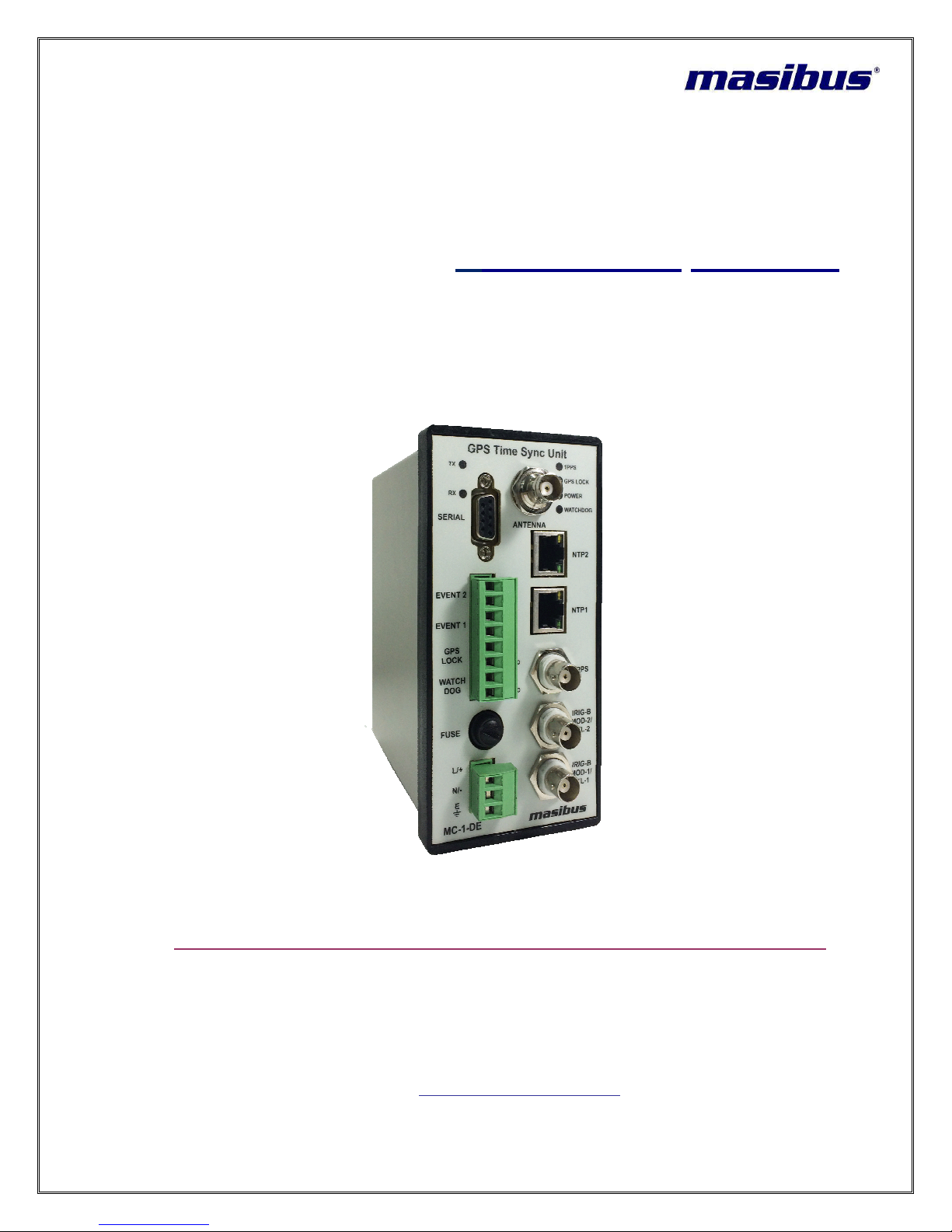
The GPS TIME SYNC UNIT MC-1-DE unit occupies the size 72mm(H) X 143mm(L) X 140mm(D) (IP
20 Enclosure).It is supplied complete with all hardware and software required for the installation, in-
cluding the Antenna, Antenna mounting kit, 15 meters Antenna cable ,02 meter RS – 232 cable and
02 meters RG58 Co-axial cable. (Depends upon commercial terms & condition also as per order)
Notice
The contents of this manual are subject to change without notice as a result of continuous improve-
ments to the instrument’s performance and functions.
Every effort has been made to ensure accuracy in the preparation of this manual. Should any errors
or omissions come to your attention, however, please inform MASIBUS Sales office or sales repre-
sentative. Under no circumstances may the contents of this manual, in part or in whole, be tran-
scribed or copied without our permission.
All description related to output ports are applicable if covered in ordering code.
Limited Warranty
Masibus Automation and Instrumentation Pvt. Ltd. Provides limited warranty for its manufactured
product against the defects in material shipped, workmanship under normal use and service for the
period of 12 months from the date of shipment of product. This warranty shall not apply if the product
is used contrary to the instructions in its manual or is otherwise subject to misuse, abnormal opera-
tions, accident, lightning or transient surges, repairs or modifications not performed by Masibus Au-
tomation and Instrumentation Pvt. Ltd.
Necessary items packed with GPS Time Sync Unit such as antenna, lightening arrestor, antenna line
amplifier and other accessories are also provided with limited warranty of 12 months from the date of
shipment.
Masibus Automation and Instrumentation Pvt. Ltd. Obligation under this warranty is limited to in facto-
ry, service and repair, of the product or the component thereof, which is found to be defective. If the
defect Is found for which Masibus Automation and Instrumentation Pvt. Ltd. Is not responsible for the
defect or the cause of defect in product, the service or repair will be done on the charge basis, on
which the buyer agrees.
For warranty service or repair, products if returned to a service facility at Masibus Head Office, buyer
shall prepay all shipping charges to Masibus, and Masibus may pay shipping charges incurred in re-
turning the product to Buyer. However, Buyer shall pay all shipping charges, duties and taxes for
products returned to Buyer in a country other than in India. Masibus highly recommends that prior to
returning equipment for service work, our technical/Customer support department is contacted to pro-
vide trouble shooting assistance while the equipment is still installed.
EXCEPT FOR THE LIMITED WARRANTY STATED ABOVE, MASIBUS AUTOMATION AND IN-
STRUMENTATION PVT. LTD. DISCLAIMS ALL WARRANTIES OF ANY KIND WITH REGARD TO
ITS PRODUCTS OR OTHER MATERIALS PROVIDED BY MASIBUS, INCLUDING WITHOUT LIMI-
TATION ANY IMPLIED WARRANTY OR MERCHANTABILITY OR FITNESS FOR A PARTICULAR
PURPOSE.
Masibus Automation and Instrumentation Pvt. Ltd. shall have no liability or responsibility to the origi-
nal customer or any other party with respect to any liability, loss, or damage caused directly or indi-
rectly by its product, material, or software sold or provided, replacement parts or units, or services
provided, including but not limited to any interruption of service, excess charges resulting from mal-

Model: MC-1-DE
Doc Ref. No:-m05dom102
Issue No:-00
Page 7 of 76
User’s Manual
functions of hardware or software, loss of business or anticipatory profits resulting from the use or
operation of the Masibus product or software, whatsoever or howsoever caused. In no event shall
Masibus be liable for any direct, indirect, special or consequential damages whether the claims are
grounded in contract, tort (including negligence), or strict liability.
Masibus Automation and Instrumentation Pvt. Ltd. Offers extended warranty period beyond standard
warranty. However, extended warranty can be ordered not later than the last month or year of stan-
dard warranty package.
Trademarks
Our product names or brand names mentioned in this manual are the trademarks or registered
trademarks of Masibus Automation and Instrumentation (P) Ltd. (herein after referred to as masibus).
Adobe, Acrobat, and Postscript are either registered trademarks or of Adobe Systems Incorporated.
All other product names mentioned in this user's manual are trademarks or registered trademarks of
their respective companies.
Product Ordering Code
ORDERING CODE
Model Output 1 Output 2#Output 3#Output 4 Output 5#Power Supply Antenna
Cable Length
MC-1-DE
X
X
X
X
X
X
X
0 None 0 None 0 None 0 None 0 None U1 85-
264V AC /
120-300V DC
1 15 Meter
1 1 NTP
1 IRIG-B AM
1 IRIG-B AM
1 RS232
1 2 Event o/p
U2 18-75V DC 2 30 Meter
2 2 NTP
2 IRIG-B TTL
2 IRIG-B TTL
2 RS485
2 2 Event o/p
+ Alarm o/p
3 50 Meter
3 Alarm o/p
4 100
Meter
S Special
X- Specify from table
*Contact factory for External Display Unit if required
# IRIG B IEEE1344 option will work along with NTP o/p or Serial o/p only
Event o/p option will work along with Serial o/p only

Model: MC-1-DE
Doc Ref. No:-m05dom102
Issue No:-00
User’s Manual
Page 8 of 76
2. Unpacking the MC-1-DE
Upon receipt, carefully examine the carton and its contents. If there is damage to the carton those re-
sults in damage to the unit, contact the carrier immediately. Retain the carton and packing materials
in the event the carrier wishes to witness the shipping damage. Failing to report shipping damaging
immediately may forfeit any claim against the carrier.
Remove the packing list from the envelope on the outside of the carton. Check the packing
list .Against the contents to be sure all items have been received, including an instruction manual.
2.1 Packing List
2.1.1 Standard Items
Each GPS TIME SYNC UNIT MC-1-DE is shipped with the following:
•GPS TIME SYNC UNIT, Model MC-1-DE time source with Regular outputs.
•Antenna Cable RG6/RG8 as per specified cable length in Customer Order / quote.
•GPS Antenna and Antenna Clamp integrated
•2 meters RG58 BNC Cable – Qty: 1
•2 meters RJ45 Ethernet Cable – Qty: 1
•2 meters RS-232 GPS Configuration Cable – Qty: 1
•Documents – User Manual and supporting Appendix manuals, Test Report, Test Certificates(On
Customer Request only)
•CD for Masibus NTP Utility Software – Qty: 1
NOTE: Antenna Cable type (RG6 / RG8) and antenna cable length (15 meters / 30 meters / 50 me-
ters / customized) is shipped only as per customer order. RG8 cable is provided if antenna cable
length requirement is more than 50 meter. All Packaging list depends upon commercial terms and
condition also as per order.
2.1.2 Optional Items
GPS TIME SYNC UNIT MC-1-DE model can also be shipped with below optional items only as per
customer order.
•Unit Power Supply Cord
•Antenna Cable type and Antenna Cable length
•Lightening Arrestor
•In-Line Antenna Amplifier
•Antenna Splitter
•Antenna holding Mast (of specified length) and its holding clamps
•Antenna Cable GI Conduit

Model: MC-1-DE
Doc Ref. No:-m05dom102
Issue No:-00
Page 9 of 76
GPS TIME SYNC UNIT MC-1-
DE
rate time output with 1PPS signal. Satellite Navigation system is a system of satellites that provide
autonomous geo-
spatial positioning with global coverage. It allows small
termine their location (longitude,
ing time signals
transmitted along a
tion system that is used multiple navigation systems mainly GPS and GLONASS. GNSS als
satellite navigation systems of SBAS, QZSS, Galileo systems etc.
GPS satellite navigation system is maintained by United States of America since 1994 which consists
of at-
least 24 operational satellites out of 32 satellites in six orbital planes
proximately 20,200
km. In typical GPS operation, four or more satellites must be visible to obtain an
accurate result. Satellite-
based navigation systems use a version of
through calculations
involving information from a number of satellites.
If one considers Figure 1 which shows a flat plane. X and Y are two known fixed points on the plane.
P is an unknown point. If the distances PX and PY can be measured, then the position of point P can
be calculated. Actually there is an ambiguity in that p
can be resolved if the position of a third fixed point Z is known since PZ is different to P’Z. This can be
summed up by saying that the unknown point P lies at the intersection of three circles based on the
known points X, Y and Z.
When the plane becomes three dimensional spaces, the circles become spheres. The intersection of
two sphere is a circle, and the intersection of three spheres is a pair of points analogous to the points
P and P’ of the flat plane c
ase. As for the flat plane case a measurement from an extra fixed point is
required to absolutely resolve the ambiguity, although in many cases the ambiguous point would be
below the surface of the world. Thus to achieve the objective, GPS must provide acc
ment of distance from the unknown location of the receiver to 4 known points.
3.
GPS Fundamentals
DE
device is a GPS/GNSS based receiver Unit
which provides acc
rate time output with 1PPS signal. Satellite Navigation system is a system of satellites that provide
spatial positioning with global coverage. It allows small
electronic
termine their location (longitude,
latitude, and
altitude) to high precision (within a few meters) u
transmitted along a
line of sight by radio from
satellites. GNSS is a satellite navig
tion system that is used multiple navigation systems mainly GPS and GLONASS. GNSS als
satellite navigation systems of SBAS, QZSS, Galileo systems etc.
GPS satellite navigation system is maintained by United States of America since 1994 which consists
least 24 operational satellites out of 32 satellites in six orbital planes
orbiting at an altitude of a
km. In typical GPS operation, four or more satellites must be visible to obtain an
based navigation systems use a version of
triangulation
to locate the user,
involving information from a number of satellites.
Figure 1 Basics of GPS
If one considers Figure 1 which shows a flat plane. X and Y are two known fixed points on the plane.
P is an unknown point. If the distances PX and PY can be measured, then the position of point P can
be calculated. Actually there is an ambiguity in that p
oint P’ would also fit the measurements. This
can be resolved if the position of a third fixed point Z is known since PZ is different to P’Z. This can be
summed up by saying that the unknown point P lies at the intersection of three circles based on the
When the plane becomes three dimensional spaces, the circles become spheres. The intersection of
two sphere is a circle, and the intersection of three spheres is a pair of points analogous to the points
ase. As for the flat plane case a measurement from an extra fixed point is
required to absolutely resolve the ambiguity, although in many cases the ambiguous point would be
below the surface of the world. Thus to achieve the objective, GPS must provide acc
ment of distance from the unknown location of the receiver to 4 known points.
User’s Manual
GPS Fundamentals
which provides acc
u-
rate time output with 1PPS signal. Satellite Navigation system is a system of satellites that provide
electronic
receivers to de-
altitude) to high precision (within a few meters) u
s-
satellites. GNSS is a satellite navig
a-
tion system that is used multiple navigation systems mainly GPS and GLONASS. GNSS als
o include
GPS satellite navigation system is maintained by United States of America since 1994 which consists
orbiting at an altitude of a
p-
km. In typical GPS operation, four or more satellites must be visible to obtain an
to locate the user,
If one considers Figure 1 which shows a flat plane. X and Y are two known fixed points on the plane.
P is an unknown point. If the distances PX and PY can be measured, then the position of point P can
oint P’ would also fit the measurements. This
can be resolved if the position of a third fixed point Z is known since PZ is different to P’Z. This can be
summed up by saying that the unknown point P lies at the intersection of three circles based on the
When the plane becomes three dimensional spaces, the circles become spheres. The intersection of
two sphere is a circle, and the intersection of three spheres is a pair of points analogous to the points
ase. As for the flat plane case a measurement from an extra fixed point is
required to absolutely resolve the ambiguity, although in many cases the ambiguous point would be
below the surface of the world. Thus to achieve the objective, GPS must provide acc
urate measure-

Model: MC-1-DE
Doc Ref. No:-m05dom102
Issue No:-00
User’s Manual
Page 10 of 76
GLONASS based satellite navigation system is maintained by Russia, a fully functional navigation
constellation in 1995. After the collapse of the Soviet Union, it fell into disrepair, leading to gaps in
coverage and only partial availability. It was recovered and fully restored in 2011. It provides an alter-
native to Global Positioning System (GPS) and is the second alternative navigational system in oper-
ation with global coverage and of comparable precision.
A fully operational GLONASS constellation consists of 24 satellites, with 21 used for transmitting sig-
nals and three for in-orbit spares, deployed in three orbital planes. The three orbital planes' ascending
nodes are separated by 120° with each plane containing eight equally spaced satellites. The orbits
are roughly circular, with an inclination of about 64.8°, and orbit the Earth at an altitude of 19,100 km,
which yields an orbital period of approximately 11 hours, 15 minutes. The overall arrangement is
such that, if the constellation is fully populated, a minimum of 5 satellites are in view from any given
point at any given time. This guarantees for continuous and global navigation for users world-wide.
A characteristic of the GLONASS constellation is that any given satellite only passes over the exact
same spot on the Earth every eighth sidereal day (1 sidereal day = 23 hours, 56 minutes, 4.0916
seconds). However, as each orbit plane contains eight satellites, a satellite will pass the same place
every sidereal day. For comparison, each GPS satellite passes over the same spot once every side-
real day. So opposed to the GPS the ground-track of the GLONASS satellites do not repeat after one
day. This avoids the resonance effects which makes station keeping of GPS satellites difficult and
expensive.
In GPS navigation system, all satellites operates at same frequency at 1.57542 GHz (as L1 signal)
and 1.2276 GHz (as L2 signal) using CDMA technique whereas GLONASS navigation system, all sa-
tellites operate on different frequencies using originally a 25-channel frequency FDMA technique
spanning from 1602.5625 MHz to 1615.5 MHz, known as the L1 band.
As GNSS uses navigation satellite system of GPS, GLONASS and other available systems in space,
GNSS receivers can easily observer 10 to 12 satellites at a time. As more number of satellites are
visible, more accuracy in receivers output signals are achieved.
Each visible satellite broadcast two types of information in its message format i.e. Almanac and
Ephemeris. Almanac data is course orbital parameters for all visible satellites. Each visible satellite
broadcasts Almanac data for all visible satellites. This Almanac data is not very precise and is consi-
dered valid for up to several months. Ephemeris data by comparison is very precise orbital and clock
correction for each visible satellite and is necessary for precise positioning. Each visible satellite
broadcasts only its own Ephemeris data. The ephemeris is updated every 2 hours and is usually valid
for 4 hours.

Model: MC-1-DE
Doc Ref. No:-m05dom102
Issue No:-00
Page 11 of 76
User’s Manual
4. MC-1-DE Specification
RECEIVER
CHARACTERISTICS
Timing Accuracy
< 15 ns with GPS Receiver (Receiver is locked on fixed position)
Positioning Accuracy
<10m SEP (with Selective Availability [SA] Disabled).
Receiver Input
1575.42 MHz L1 C/A Code.
Tracking
12 parallel channels.
Acquisition Time
Hot Start : <5 s
Warm Start: <38 s
Cold Start : < 45 s
Memory Backup
Internal 17 mAh cell, Sufficient for 2 weeks of backup time
It requires 72 hours run for full charging.
Antenna
Active L1 GPS, 30 dB Gain
Cable: RG 6 / RG 8 (Optional coaxial cable)

Model: MC-1-DE
Doc Ref. No:-m05dom102
Issue No:-00
User’s Manual
Page 12 of 76
Maximum Length: 100 meters (Up-to 400 meters using additional line am-
plifier)
Coverage: 360 Degree
Ingress Protection: IP20
OUTPUTS
Pulse
1 PPS
Accuracy: <150 ns Accuracy with GPS locked
Output: TTL Output (Impedance 250 Ω)
Pulse Width: 200 (200 mS High & 800 mS Low signal)
Interface: BNC Female connector (Front Panel)
Serial
COM1
Protocol: NGTS/ T-format/NMEA
Port Settings: 4800/9600/19200/38400/57600/19200, Programmable
baud rate ,stop bit, parity bit and message format
Output: Isolated RS232/RS485** (Factory Configurable)
Interface: DB9 Female Connectors (Front Panel)
OUTPUTS
Alarms
Two Isolated Dry Contacts to 230 VAC / 24VDC, 10 A:
1. GPS Lock
2. Watchdog
IRIGB-TTL -
DC Level Shift (DCLS)
Format: IRIG-B(007) or IEEE 1344 (Field set)
Output: TTL into 50 Ω
Interface: BNC Female connector (Front Panel)
IRIGB- Amplitude Modulated
Format: IRIG-B(127) or IEEE 1344/C37.118-2005 (field set)
Signal: 1 KHz AM Signal
Modulation Ratio: 3:1
Output: 3.3Vp-p to 10Vp-p, into 100Ω
Interface: BNC Female connector (Front Panel)
Ethernet Output
Time Synchronization protocols: NTP/SNTP Server
NTP: Network Time Protocol (Version 3)
RFC: RFC- 1119, RFC- 1305
SNTP: Simple Network Time Protocol (Version 3)
RFC: RFC- 1361
Internet protocol: IPv4

Model: MC-1-DE
Doc Ref. No:-m05dom102
Issue No:-00
Page 13 of 76
User’s Manual
Mode:
Server
Time format: UTC
Network Interface: 10/100 Mbps
Interface: RJ-45 Connector (Front Panel)
Additional Event Outputs
Two independent configurable Event outputs
Configuration: Individual configurable time period and pulse ON time
through Serial Terminal
Time Period: 1 to 86400 seconds (24 Hr.) max
ON Time: min. 50 milliseconds and max 50% of period time set for particu-
lar event
Event contact capacity: 350 VDC, 120mA maximum
Interface: 4-Way Terminal Strip (Front Panel)
INTERFACE
Status LED
Power : Red
1 PPS : Red
Watchdog : Red
GPS Locked : Green(GPS LOCK)
TX : Red (Available only when serial output is available)
RX :Red (Available only when serial output is available)
Programming
Using HyperTerminal in a local PC via serial terminal.
Programmable parameters:
Global Time zone correction
Serial data format selection (NGTS or T-FORMAT or NMEA)
Password Protection
Network Settings:
IP address, Subnet mask, Gateway and SNMP Manager IP addresses
configurable through Telnet remote login.
All network configurations are password protected.
POWER SUPPLY
AC
: 85 to 264 V, 47-440 Hz
DC: 125-300 V
Power Consumption: <10W Typical (40W Max)
Compliance
:
EN55011(CISPR11), EN55022 (CISPR22) Class B
OPTIONAL
POWER SUPPLY
DC:
18 – 75 V
Power Consumption: 10W Max
PHYSICAL DIMEN-
SIONS
Width:
143mm
Depth: 140 mm
Height: 72mm
Weight: 0.9 Kg(Approx)

Model: MC-1-DE
Doc Ref. No:-m05dom102
Issue No:-00
User’s Manual
Page 14 of 76
ENVIRONMENT
Temperature
Operating: 0° C to +55° C
Storage: -20° C to +80° C
Humidity
20 - 90% (Non-condensing)
EXTRA MODULES
(OPTIONAL)
RS232-to-RS485 Converter
LINE AMPLIFIER, SURGE ARRESTOR
Time Distribution Rack (TDR-4)
Time Signal Repeater (TSR-4)
Day Display Unit (DDU-XX)
Netser (NGTS to NTP Convertor)
Isolation (With-
standing voltage)
Between primary terminals* and secondary terminals**:
At least 1500 V AC for 1 minute
Between primary terminals* and grounding terminal:
At least 1500 V AC for 1 minute
Between grounding terminal and secondary terminals**:
At least 1500 V AC for 1 minute
Between secondary terminals**:
At least 500 V AC for 1 minute
* Primary terminals indicate power terminals and relay output terminals.
** Secondary terminals indicate Output Ports.
Insulation resistance: 20MΩor more at 500 V DC between power terminals
and grounding terminal.

Model: MC-1-DE
Doc Ref. No:-m05dom102
Issue No:-00
Page 15 of 76
This section provides
description of
5.1
GPS TIME SYNC UNIT
Below image shows
GPS TIME SYNC UNIT
6 LED status indicators and v
arious outputs of
Front panel of unit
Figure 2
GPS Time Sync Unit
1.
Power Input :
5.
Unit Front Panel Description
description of
Din Rail GPS MC-1-DE
unit front panel user applicable interface.
GPS TIME SYNC UNIT
MC-1-DE Front Panel
GPS TIME SYNC UNIT
MC-1-DE
model front panel. The front panel is equipped
arious outputs of
GPS Time Sync Unit MC-1-DE
device is provided at
GPS Time Sync Unit
Model MC-1-DE Front Panel
Figure 3 Power Supply terminals
User’s Manual
Unit Front Panel Description
unit front panel user applicable interface.
model front panel. The front panel is equipped
device is provided at

User’s Manual
2.
Fuse Connector :
GPS TIME SYNC UNIT MC-1-
DE
3. Relay Output :
GPS TIME SYNC UNIT MC-1
through 4
pin female connector.
NO terminals.
4. Event Output :
GPS TIME SYNC UNIT MC-1-
DE
output provides pulse at configured event interval with pre
are Opto -
MOS output (optically coupled solid state Relay output) provided through
connector
5. Serial Output :
Serial terminal on Front panel
is RS
in figure 7.
GPS TIME SYNC UNIT
mat on its term
inal and can also be used for
Doc Ref. No:
Figure 4 Fuse
DE
provide fuse of 3.15 A.
Figure 5 Alarm Relay Terminals
1
-DE provide two
relay outputs for Watchdog and GPS LOST alarm
pin female connector.
Factory set Relay contact provided on Front
panel connector are C
Figure 6 Additional event Terminals
DE
has the capability to provide two event outputs .
The single event
output provides pulse at configured event interval with pre
-
configured pulse width. This pulse outputs
MOS output (optically coupled solid state Relay output) provided through
Figure 7 Serial Output Terminal
is RS
-232/RS-485 electrical standard DB-
9 female connector as shown
GPS TIME SYNC UNIT
MC-1-DE provides serial time frame T-
format / NGTS
inal and can also be used for
GPS TIME SYNC UNIT MC-1-DE
configuration. This
Model: MC-1-DE
Doc Ref. No:
-m05dom102
Issue No:-00
Page 16 of 76
relay outputs for Watchdog and GPS LOST alarm
panel connector are C
-
The single event
configured pulse width. This pulse outputs
MOS output (optically coupled solid state Relay output) provided through
4 pin female
9 female connector as shown
format / NGTS
/ NMEA for-
configuration. This

Model: MC-1-DE
Doc Ref. No:-m05dom102
Issue No:-00
Page 17 of 76
terminal connection will be as per RS
specified during unit order. If nothing specified, the
232 electrical standard output.
If Configuration of serial
terminal is as per RS
3 and Pin5) can be used for configuration and to provide serial time frame to other periphe
figuration of COM1 terminal is as per RS
and Pin 8 will be D- line.
6. LED status for TX/RX
This LED illumination is RED color
Available only when serial output is available.
7. IRIG – B1 Output
GPS TIME SYNC UNIT MC-1-
DE
tor on Front
panel of unit as shown in
8. IRIG – B2 Output
GPS TIME SYNC UNIT MC-1-
DE
tor on Front
panel of unit as shown in
9. 1PPS Output
GPS TIME SYNC UNIT MC-1-
DE
on front
panel of unit as shown in
terminal connection will be as per RS
-232 electrical standard or RS-
485 electrical standard as per
specified during unit order. If nothing specified, the
factory set settings of Serial
terminal is as per RS
-
232 standard, cross cable (having connection on Pin2,
3 and Pin5) can be used for configuration and to provide serial time frame to other periphe
figuration of COM1 terminal is as per RS
-485 standard, Pin 7 of DB-
9 connector will act as D+ line
This LED illumination is RED color
and it indicates transmission and reception through serial te
Available only when serial output is available.
DE
provides IRIG-B TTL and IRIG-
B AM output through BNC conne
panel of unit as shown in
Figure 8. IRIG – B TTL / AM can be
Factory Selectable
Figure 8 IRIG B Output Terminal
DE
provides IRIG-B TTL and IRIG-
B AM output through BNC conne
panel of unit as shown in
Figure 9. IRIG – B TTL / AM can be Factory
Selectable.
Figure 9 IRIG B Output Terminal
Figure 10 1PPS Output Terminal
DE
provides 1PPS output at TTL signal level through BNC connector
panel of unit as shown in
Figure 10.
User’s Manual
485 electrical standard as per
terminal is as per RS
-
232 standard, cross cable (having connection on Pin2,
3 and Pin5) can be used for configuration and to provide serial time frame to other periphe
rals.If Con-
9 connector will act as D+ line
and it indicates transmission and reception through serial te
rminal.
B AM output through BNC conne
c-
Factory Selectable
.
B AM output through BNC conne
c-
Selectable.
provides 1PPS output at TTL signal level through BNC connector

User’s Manual
10. NTP1
GPS TIME SYNC UNIT
MC
and Telnet communication as shown in
11. NTP2
GPS TIME SYNC UNIT
MC
and Telnet communication as shown in
12. Antenna
GPS TIME SYNC UNIT MC-1-
DE
ing GPS antenna
as shown in figure
to antenna. Refer Antenna Installation section
13.
LED status Indicators:
There are total 4
other status indicators.
•POWER
: This LED illumination is RED color. This LED indicates the presence of power to
unit.
•1PPS: This
LED indicates the presence of 1PPS signal from GPS receiver module. It blinks
at every one second. The illumination is of RED color.
•WATCHDOG
: This LED illumination is RED color. This LED is ON when the unit becomes
unhealthy due to GPS receiver module
•GPS LOCKED
: This LED illuminates GREEN color if the GPS satellites signal
and GPS is LOCKED,
and
Doc Ref. No:
MC
-1-DE
is equipped with 10/100 Mbps Ethernet output for NTP, SNMP
and Telnet communication as shown in
figure 11.
Figure 11 NTP1 Output Terminal
MC
-1-DE
is equipped with 10/100 Mbps Ethernet output for NTP, SNMP
and Telnet communication as shown in
figure 12.
Figure 12 NTP2 Output Terminal
Figure 13 Antenna Output Terminal
DE
device have a BNC female connector at its Front
as shown in figure
13. This connector provides 5 VDC
(4.7V DC to 5.2V DC)
to antenna. Refer Antenna Installation section
6 for connecting GPS Antenna.
There are total 4
LED indicators including power led indication and
: This LED illumination is RED color. This LED indicates the presence of power to
LED indicates the presence of 1PPS signal from GPS receiver module. It blinks
at every one second. The illumination is of RED color.
: This LED illumination is RED color. This LED is ON when the unit becomes
unhealthy due to GPS receiver module
failure or internal failure.
: This LED illuminates GREEN color if the GPS satellites signal
and
stay off if no GPS satellites are available.
Model: MC-1-DE
Doc Ref. No:
-m05dom102
Issue No:-00
Page 18 of 76
is equipped with 10/100 Mbps Ethernet output for NTP, SNMP
panel for connect-
(4.7V DC to 5.2V DC)
supply
LED indicators including power led indication and
three
: This LED illumination is RED color. This LED indicates the presence of power to
LED indicates the presence of 1PPS signal from GPS receiver module. It blinks
: This LED illumination is RED color. This LED is ON when the unit becomes
: This LED illuminates GREEN color if the GPS satellites signal
s are available

Model: MC-1-DE
Doc Ref. No:-m05dom102
Issue No:-00
Page 19 of 76
User’s Manual
6. GPS TIME SYNC UNIT MC-1-DE Installation
Before beginning with unit installation, please follow important safety statements for avoiding in-
stallation practices causing malfunctioning of the device as mentioned below.
It is recommended to get the installation of this product to be done
by authorized service personnel of the manufacturing company or
by the trained and qualified operator in co-ordination with autho-
rized service personnel of the manufacturer company.
Installation of the equipment is to be complied in accordance with
local and national electrical codes.
This equipment is sensitive to Electrostatic Discharge (ESD). Ob-
serve all ESD safeguards while using this equipment.
This equipment can be damaged if incorrect power source voltage
is applied.
This equipment can be damaged if power source is applied with
incorrect polarity on its respective terminal.
Never plug unit power supply connector or power supply cables in
terminal while main power source is ON.
This equipment should be always used with earth grounded. Never
defeat the ground connector or operate the equipment in the ab-
sence of suitable earth ground connection.
Never work on open unit when power of unit is ON.

Model: MC-1-DE
Doc Ref. No:-m05dom102
Issue No:-00
User’s Manual
Page 20 of 76
Unit is equipped with internal fuse. If it is blown Up or blowing again
on its replacement, it is highly probable that either power source is
incorrect or power source connection is improper.
Internal fuse should be only replaced with same fuse type and
same fuse rating as supplied from manufacturer factory. Replace-
ment of Fuse should be done in unit Power OFF condition only.
6.1 GPS Antenna and Cable Information
GPS TIME SYNC UNIT MC-1-DE comes complete with the necessary hardware to be able to receive
GPS signals: 50-feet of RG-6 cable and a GPS antenna. The antenna cable is connected between
the female N connector on the antenna and the female BNC connector at the Front panel of the Unit.
This section should help you with installing the GPS antenna and antenna cable(s) and connecting
them to the model GPS TIME SYNC UNIT MC-1-DE. It should also be a source of information if you
should need to trouble shoot the antenna cable system. These Unit achieve their accuracy. By com-
paring and adjusting the internal clock signal to the incoming GPS signal.
6.1.1 Terminal connection for Wall/Rack/Table Top Mount Enclosure
Refer steps for installation of GPS antenna and antenna cable as described below.
Selecting a GPS Antenna Site Outdoors
Select a site or antenna mounting position that...
• check the highest point available.
• Offers a full 360° view horizontally, to within 10° vertically of the horizon
• Is higher than neighboring buildings/obstructions
• Is protected from strong radio frequency (RF) and microwave transmissions
• Is set away from RF-reflective surfaces that cause multipath interference
• Is set 3 ft. (1 m) away from other GPS antennas
Avoid...
• Mounting the antenna between tall buildings or next to walls and equipment
• Cable type and cable length which runs from the antenna to the receiver that exceed the
Specified length.
• Patching multiple cables together to make a single cable run
• Running the cable through bulkheads and alongside high-energy cables
• Crimping or damaging the cable
Blocked signals and multipath cancellation may significantly increase GPS signals acquisition time.
Multipath Cancellation is caused by reflected signals that reach the antenna out of phase with the di-
rect signal due to vertical reflective objects positioned to the side and above the antenna. To solve
these problems, user must mount the antenna at least 1 meter away from and above the reflecting
surface.
To properly receive GPS signals, the GPS antenna needs to be mounted clear of buildings as sur-
rounding elements or heighted obstacles may block the GPS signals transmission done with the sa-
tellites. For complete antenna signals coverage, the antenna needs to have a clear view of the sky
This manual suits for next models
1
Table of contents
Popular Clock manuals by other brands

König Electronic
König Electronic WEST102GY manual

Wooden-Gear-Clocks
Wooden-Gear-Clocks Clockerel Build manual

Perel
Perel WC115 user manual

Conrad Electronic
Conrad Electronic Eqwu 880 operating instructions

Bresser
Bresser 80-20410 instruction manual

Mobatime
Mobatime TREND NTP Series Mounting and instruction manual

Primex
Primex XR PERSONAL SERIES Installation & user guide

TimeMoto
TimeMoto TM-616 Quick installation guide

AirTime
AirTime AT12RM installation instructions

Bresser
Bresser 8020215 instruction manual

Howard Miller
Howard Miller Seville instruction manual

La Crosse Technology
La Crosse Technology WT-3161WH user manual