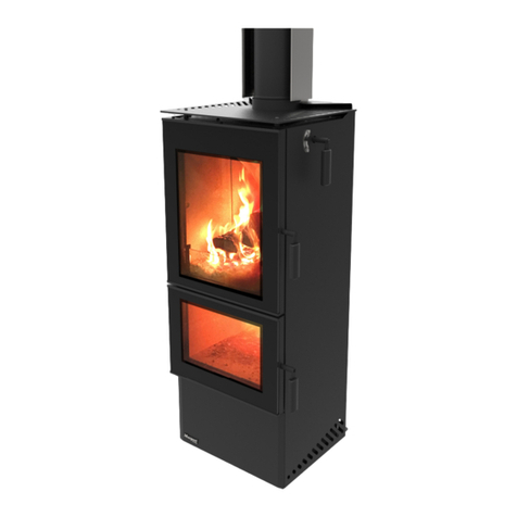
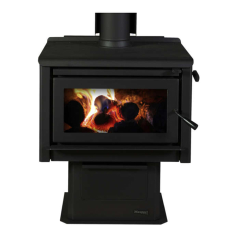
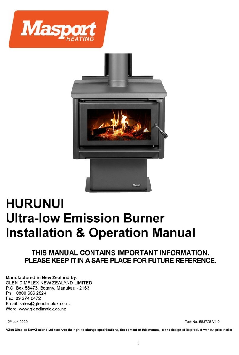
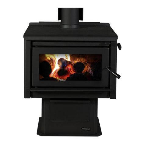
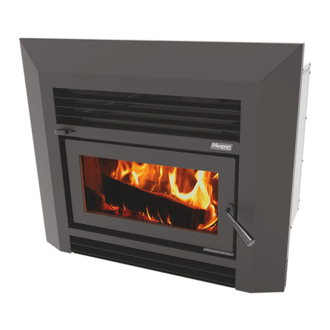
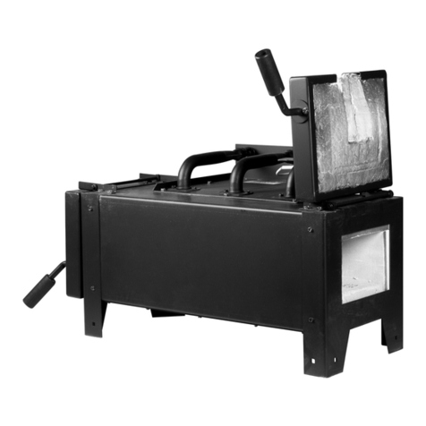
Masport CLUTHA User manual

1
CLUTHA
Ultra-low Emission Burner
Installation & Operation Manual
THIS MANUAL CONTAINS IMPORTANT INFORMATION.
PLEASEKEEPITINASAFEPLACEFORFUTUREREFERENCE.
Manufactured in New Zealand by:
GLEN DIMPLEX NEW ZEALAND LIMITED
P.O. Box 58473, Botany, Manukau - 2163
Ph: 0800 666 2824
Fax: 09 274 8472
Web: www.glendimplex.co.nz
Part No. 599586 V1.0
*Glen Dimplex New Zealand Ltd reserves the right to change specifications, the content of this manual, or the design of its product without prior notice.

2
CONTENTS
Section
PAGE
1
INTRODUCTION
3
2
ITEMS SUPPLIED WITH THE FIRE
3
3
HANDLING AND TRANSPORT
3
4
NOTES
4
4.1
CAUTIONS
4
5
TECHNICAL SPECIFICATIONS / SEIZMIC RESTRAINT
5
5.1
ALCOVE/RECESS INSTALLATION
6
5.3
REDUCING CLEARANCES
6
6
ASH HEARTH REQUIREMENTS
6
7
UNPACKING
6
8
POSITIONING
7
9
FLUE REQUIREMENTS
7
10
BRICK AND BAFFLE LAYOUT
7
11
FIRST BURN AND PAINT CURING
8
12
FUEL
8
12.1
WOOD MOISTURE
8
13.1
KINDLING INTERMEDIATE AND MAIN WOOD DETAIL
8
13.2
INITIAL LIGHT UP WITH KINDLING AND INTERMEDIATE LOAD
9
13.3
INTERMEDIATE LOAD 2 AND MAIN LOAD
9
13.4
CONTROLLING THE HEAT OUTPUT
9
13.5
REFUELING
9
14
ASH
10
15
OPTIMIZING THE BEST PERFORMANCE FROM YOUR HEATER
10
16
MAINTENANCE
10 & 11
17
REPLACEMENT PARTS
11 & 12
18
COMMON ISSUES AND PROBLEM SOLVING
12
19
FLUE TERMINATION REQUIREMENTS
13
20
WARRANTY TERMS AND CONDITIONS
14 & 15
21
FLUE SYSTEM INSTALLATION DIAGRAMS
16
22
WARRANTY REGISTRATION FORM
17

3
1.0 Introduction
Congratulations!
You are now the owner of a MASPORT Clutha” Ultra Low Emission wood Burner designed and
developed by Glen Dimplex New Zealand Ltd.
Firstly, thank you for purchasing a Masport appliance.
Your new generation wood fire has been designed to provide you with all the warmth and comfort
needed whilst having ULTRA LOW emissions to dramatically reduce the impact on the environment.
Environment Canterbury has approved the installation of this burner throughout New Zealand, as it
bears the MASPORT brand, it promises to provide you with the economy, safety, and efficiency and
quality.
To make the most of your appliance, installing, operating, and maintaining the burner correctly is
important. Please read this installation and operations manual carefully before installing or
operating your Clutha ULEB. Please take the time to understand the basic principles of this new
burner which uses the latest combustion technology.
The bricks fitted in this burner are of a ceramic composition which will store invaluable heat to be
released towards the end of the burn cycle whilst also reflecting heat into the ember bed creating a
high combustion environment as well as increasing the radiating heat through the door glass. The
baffle is made of stainless steel and supplies secondary air to aid the combustion process making
for a cleaner hotter burn. This type of construction makes the heat durable and can reduce service
costs in the long run.
2 Items supplied with the fire
1 x Masport ceiling plate
1 x St/St Main Baffle
7 x Ceramic Bricks
1 x Installation and Operation Manual which includes
•The Technical and Clearance Specification.
•Installation guidelines
•The Brick & Baffle Layout
3 Handling and Transport
The Clutha appliance has a Nett weight of 118kg
Masport recommends that a minimum of 2 people handle the heater while moving it around and
positioning
It is also recommended that suitable handling and safety equipment be used where applicable,
removing items like the baffle, bricks and the door will help reduce weight of the heater during
installation process.
Supplied in a wooden crate to reduce the risk of transport damage, if there is any visible damage to
the crate, please inspect the heater and notify your retailer if there is any damage.
4 Notes
•The installation of the Clutha ULEB requires a building consent before installation commences.
Check with your local Building Authority whether there are any additional requirements before
installing.
•The burner and flue system shall be installed in accordance with AS/NZS 2918:2001 and
appropriate requirements of the relevant local building codes.
•Masport highly recommends NZHHA trained SFAIT (Solid Fuel Appliance Installation technician)
installer to install your burner. Your dealer or heating specialist will be able to help with
recommendations and advice on permits/consents required for the installation in your area.

4
•Please read carefully all the dimensions and recommendations provided in the technical
specification section of this manual. The dimensions given comply with the required safety
standard AS/NZS 2918:2001.
•For safety, operational and warranty compliance, altering the appliance in any way, should not be
attempted, No modifications are permissible.
•Please ensure that only components approved by Masport heating New Zealand are used on the
installation, as substitutes may adversely affect performance and might nullify compliance with the
requirements of AS/NZS 2918 safety standards.
•The Clutha burner was tested using a Masport flue system, it is recommended that it is installed
using a Masport flue system or a flue system that has been tested and complies with AS/NZS
2918:2001 Appendix F. All Masport burners have been tested using a Masport double flue shield
and this must be used with your installation.
•Masport recommends that the flue system must be serviced annually by a NZHHA trained service
agent.
4.1 Cautions
•This appliance is not intended for use by persons (including children) with reduced physical,
sensory, or mental capabilities or lack of experience and knowledge unless they have been
given supervision or instruction concerning the use of the appliance by a person responsible
for their safety.
•Do not leave children unattended near the alighted fire and keep them well away from the fire
when in use. Supervise young children to ensure that they do not play with the appliance.
•Do not use flammable liquids or aerosols to start or rekindle the fire. Also, do not use such
flammable materials near this appliance when operating.
•Always keep clothing, firewood, furnishing, and other combustible materials at a safe distance
from the fire.
•Do not touch any part of the fire other than the door handle and the air control when in use, as
all other parts can be extremely hot.
•A Cracked/broken door glass makes operation of the heater unsafe. Do not operate the fire
with a cracked/broken door glass.
•Do not attempt to clean or maintain the fire when in use or with hot embers in the combustion
chamber. Ensure that embers and all other parts of the fire have cooled down completely
before starting ash removal or other maintenance.
•Do not use the fire if there is a malfunction, a suspicion of breakage, or unusual noises.
Contact your Masport dealer or customer service team at Glen Dimplex, New Zealand.
•This appliance should always be operated & maintained as per instructions in this manual.
Failure to follow above warnings, cautionary measures
and instruction given in this installation and operation
manual will void the Masport Heating warranty of this
product.

5
5 Masport Clutha - Technical Specifications
Overall Dimensions
Net Weight of the Burner
118 kg
Test Method
Emissions
mg/MJ
Emissions
g/kg
Efficiency
%
Authorization
No
Real-Life Test
Canterbury Method V1.6 (ULEB)
National Environment Standard
AS/NZS 4012/13:2014
0.46g/kg
Approx. Heating capability
Small to Medium Homes (2~3 Bedrooms)
Flue Shield
900mm Long SS Double Flue Shield (Included in the Masport flue
kit)
Flue System
Std 4.2M Long, 150mm Flue System (GDFLU013M) or Flue System
that has been tested to & comply with AS/NZS 2918:2001 Appendix F
** For installation in Canterbury & South of Canterbury, we recommend extending 200 inner
casings within 250~300 from flue termination. Also, we recommend not to use Masport Opti
or equivalent flue kits in this area, as they take ceiling or external cold air and cool the flue
casings, leading to accelerated creosote build-up in the main flue pipe.
Floor Protector Requirement
Ash Floor Protector or Steel Floor Protector
Minimum Clearances to Combustibles: Parallel, Corner & Alcove configurations with Minimum
2.4 m ceiling height.
Parallel Installation
Corner Installation
E- Cooktop Corner to Wall
144 mm
C- Glass to Floor Protector Front
300 mm
H- Flue Centre to Wall
384 mm
D- Floor Protector Side
117 mm
F- Flue Centre to Rear Wall
231 mm
G- Flue Centre to Side Wall
573 mm
N- Flue Centre to Floor
Protector Front
656mm
R- Flue Centre to Wall Corner
543 mm
WW- Overall Width of Fire
495 mm
K- Floor Protector Depth
887 mm
DD- Overall Depth of Fire
524 mm
HH- Overall Height of Fire
894 mm
Seismic Restraint - In New Zealand, it is a requirement that the wood burner and floor protector are
secured to prevent shifting in the event of an earthquake. This is best done by fastening the wood burner
right through the protector to the floor, using 8mm Dyna Bolts [ concrete floors] or 8mm coach screws or
equivalent fasteners [ wooden floors]. Seismic holes are located at the rear of the burner.
I-
Floor Protector Front Edge 428
mm
J-
Floor Protector Width 729 mm
L-
Floor Protector Diagonal 1199 mm
M-
Floor Protector Side 998 mm
A-
Rear Panel to Rear Wall
B-Cooktop Edge to Side Wall C-
Glass to Floor Protector Front68
mm
325
mm 300 mm
35
mg/MJ CRC 231303
CRC 231301
66%
NZ National Environmental Safety Test Standard
-
AS/NZS 2918:2001
NZ National
Environmental Test
Standards
-
AS/NZS 4012:2014 and AS/NZS 4013:2014.
Environment Canterbury’s Real-life test
-
Canterbury test method CM1.6
Clutha
burner model has
been tested and complies
with
the
following standards & tests:
495mm Wide x
524mm Deep x
894mm High

6
5.1 Installation in Alcove/Recess situation
The Clutha has been tested for alcove (recess) made of combustible material and complied
to the safety standard AS/NZS 2918:2001
Note –
- Refer to the table on
Page 1 for dimension
- The ceiling height must
be a minimum of
2400mm
- Dimensions are as per
above table for parallel
installation.
NOTE: Any variation to the specified clearances must be done in accordance with AS/NZ 2918 sect: 3
5.2 Reducing Clearances
The clearances to combustible specified in section 5.0 of this manual can be reduced by following
guidelines specified in AS/NZS 2918:2001 table 3.1 & 3.2.
Clearance factors for heat shield which is within 45 degrees of the vertical
Heat Shield Construction
Minimum Air Gap Dimension
Clearance Factor
Single layer of continuous material
12mm
0.4
Single layer of continuous material
25mm
0.3
Two spaced layers of continuous material
12mm+12mm
0.2
Clearance factors for heat shield which is more than 45 degrees off the vertical
Heat Shield Construction
Minimum Air Gap Dimension
Clearance Factor
Single layer of continuous material
12mm
0.8
Single layer of continuous material
25mm
0.6
6 Ash Hearth Requirements
The Clutha has been tested and met the minimum requirement for an ash hearth set out in AS/NZS
2918: 2001.
This heater weighs approx. 118kg so ensure that the floor structure is sufficient to withstand this weight,
materials used for the floor protector must also be able to withstand the weight and not crack nor break.
7 Unpacking
Remove the shipping wooden crate and packing material around the burner. Remove the loose pieces
from within the firebox. Remove and discard the screws holding the wood fire to the shipping pallet.

7
8 Positioning
Refer to minimum clearances in the above table. Note that the testing was carried out with a ceiling
height of 2.4mtrs from the ground.
Any proposed deviation from the specified clearances or installation configurations should in accordance
with AS/NZ 2918:200
9 Flue Requirements
A minimum 4.2M long, 150mm diameter Masport flue system or flue system tested in accordance with
AS/NZS 2918:2001, Appendix F shall be used with a 900mm long Masport double skin flue shield.
NOTE The Clutha has been tested and approved for the use of the Masport drop Box flue system.
It is highly recommended that the 200 inner casing of Masport flue system be extended to within
250~300mm below the top of the 250mm outer casing.
Please note that the environment may have an impact on how the flue system performs and may need
additional components added to remedy these issues, flue casings other than std height must be braced
in accordance with relevant building codes.
Flue installations other than a std vertical type are not recommended. however if an installation requires
offsets guidelines are set out with AS/NZS 2918:2001 and must be followed.
All flue pipe joints, and the flue spigot must be sealed using an appropriate fire cement, all flue pipes
must be secured using 3x 3.25mm stainless steel rivets.
Be sure that flue pipes have been sealed as this can cause issues with the draw and a lack of
performance from the heater.
10 Brick and Baffle Layout
Before the first light-up, ensure that the burner is correctly installed and signed off
by an approved installer or local council and all local council's wood fire permit
requirements have been completed satisfactorily and all components have been
fitted to the heater.

8
11 First burn & paint curing
Once your heater has been installed and meets the requirements of a consented installation you are
ready to have your first burn.
It is important to start off with a couple of small burns and not to over fuel the heater, this is because the
paint will require curing. During this process the paint will emit a blue-ish coloured smoke so it is
important to have adequate ventilation during this process. Continue to run the heater until there is no
more smoke, each burn can be progressively hotter and until the curing process is completed.
12 Fuel
The quality of the firewood you burn can considerably affect the performance of your burner.
Moisture content, tree species, and log size are the main factors affecting the performance of the wood
burner. Masport recommends using softwood, cutting your wood to a size fit into the fire box and has a
moisture content of 16 –25% range is preferable, also loading your wood in a front to back orientation is
better for performance and a cleaner burn.
DO NOT BURN
•Wood that has been treated with preservatives or impregnated with chemicals or glue
•Chipboard, particleboard, or laminated board
•Painted, stained, or oiled
•Driftwood or other salt impregnated wood
Burning such materials is not good for the environment, it can also damage the firebox and put you at
the risk of voiding the warranty your Masport heater
In NZ, radiata pine or macrocarpa are the most commonly available softwood species suitable as
firewood. Other hardwood species like eucalyptus (blue gum) can also be mixed with softwood to
achieve longer burns.
12.1 Wood Moisture
A wood moisture meter is the best way to check the moisture content of the firewood. Split a piece of
wood and then press the metering prongs firmly into the long side of a split piece to test moisture
content. 16-25% percent of moister content is ideal.
If you purchase firewood, ask for dry seasoned wood and get it checked from your wood merchant.
13.1 Kindling, intermediate and main wood loading details
Seasoned firewood pieces approx. 250mm long in various sizes should be used in the Masport Clutha.
oKindling –15 pieces cut to 1.0 kg approx
ointermediate 1 load –4 pieces total 1.2 kg, approx
ointermediate 2 load –4 pieces total 2.5kg approx
omain load –3 pieces 3kg approx.
Kindling
Intermediate 1
Intermediate 2
Main load

9
13.2 Initial light-up with kindling and intermediate load
1. Make sure the air control is set in the "HIGH" position.
2. Place the intermediate load 1 evenly across the base of the heater in a front to back direction.
3. Place the kindling pieces on to of the 4 logs, they should be stacked 5x5x5 as in image 3
4. Use 2 firelighters on the top of the kindling one in the middle and one at the rear.
5. Light the rear fire lighter than the middle fire lighter, leave the door on the safety starter latch for
approx 5-10 making sure the Kindling is well alight, now close the door.
(1)
(2)
(3)
(4)
13.3 Intermediate load 2 and main loads
6. Approximately 35mins after lighting the heater intermediate 2 can be loaded into fire.
7. Subsequent main loads should be loaded when the fuel in the heater has burnt down to good
embers, and there is minimal flame in the heater.
13.4 Controlling the heat output
Once the main load has a well-established flame the air control can now be adjusted to a lower setting.
Do not turn the air control directly from the high setting to low adjust to approximately half setting wait for
around 5-10mins the adjust to the lowest setting.
Adjusting directly from high to low will starve the fire of oxygen and result in a poor burn.
13.5 Refueling
Refueling is best done when the majority of the flame has died down and there is a good ember bed in
the heater with minimal flame, always turn the heater air control to high and leave it there for a few
minutes so the flue gasses can increase creating a good flue draught. Open the door slowly and not fast
this will stop any combustion gasses from being pulled into the room.
Place your next main load into the heater as efficiently as you can and close the door as soon as
possible, again this will reduce the risk of gasses coming back into the room..
(5)
(6)
(7)
Never leave the heater unattended during the startup phase and while the door is on the starter latch

10
14 Ash
Maintaining a good ash level will help the heater to operate more effectively, too much ash will reduce
the usable volume within the heater and effect performance so ensure that the ash does not reach the
level of the ash lip, always leave approx. 20mm of ash in the heater when cleaning the heater as this
acts as an insulator and allows air to pass into the embers aiding the combustion process.
Note when emptying ash always do it when the heater is cold and always use a steel bucket, or the
ash box on the ash model.
Dispose of the ash ONLY when it is cold.
15 Optimizing the best performance from your heater
•Using clean dry wood will help with ignition and the combustion process
•Maintaining a good hot ember bed at the start of each refueling will reduce pollutants and help with
efficiency
•Do not overfill the firebox as this will reduce air paths through the fuel and will not allow the heater
perform as intended.
•Using more medium sized pieces of wood as opposed to very large pieces will give a better burn
and will help keep the burn clean.
•Always open the air control to fully open position before refueling, do not run the heater on the low
setting permanently, and after long periods on the low setting, it is recommended the heater is run
on high to burn away any unwanted built up of particulate within the heater and flue system.
NOTE
For the heater to perform optimally it must have a good air supply, in today’s air tight homes this can
an issue so it is advised that an adequate fresh air supply be fitted into the room that the heater is
located in.
16 Maintenance
Maintaining a clean glass
Prolonged low burns, dirty wood and wet wood will cause the glass to blacken; this can be burnt off by
running the heater on the high setting for a good period. Alternatively, when the heater is cold the glass
can be cleaned by using damp newspaper and ash, glass cleaner and a cloth of a ceramic glass-
cleaning pad.
Cleaning the heater externally
Using a soft DRY cloth or soft paintbrush, gently dust/wipe the painted surfaces. Under no
circumstances use wet Cloths chemical sprays on the paint; this may cause issues with the finish of
your heater. Please note that the paint used on this heater will dull off over a period and can be
touched up Annually.
Door latch adjustment
•IT IS IMPORTANT THAT THE HEATER IS NOT USED IF THE GLASS IS BROKEN
•DO NOT USE FLAMMABLE LIQUIDS OR AEROSOLS TO START OR REKINDLE
THE BURNER
•DO NOT OPERATE THE HEATER IF EXCESSIVE SMOKE ENTERS THE ROOM

11
Open the main fuel loading door
To adjust the tension on the door rope and have a good seal, the door catch pin can be moved
forward and back, loosen the securing bolt on the inside of the firebox, move the pin toward the rear
of the fire and re-tighten, repeat until a good seal has been achieved.
Testing the door seal while adjusting the spindle, Sandwich a strip of paper between the firebox edge
and Seal, pull the paper gently and as you do there should be a resistance on the paper, adjust the
Spindle until you are satisfied a good seal has been made. The paper will be jammed or slide with
effort when the seal is good or sufficient.
Carry out this test on all four sides of the door to ensure the seal is even on all sides.
Door and Door Glass Seals
The main door seal should be checked periodically and, if required, will need to be replaced. Over time
the door and glass seals will degrade and cause air to leak into the firebox. This excess air can affect
the performance of the burner and possibly cause damage to the burner components. Air leaks can also
cause blackening of the glass.
Heat Output Control (Air Slide)
The air control on the burner should move freely, if at any time this becomes sticky have a
service technician inspect and make the appropriate adjustments to free it up.
Firebox Ceramic Bricks
The ceramic refractory bricks in your Clutha burner are an essential component for achieving a clean
and efficient burn. These bricks may degrade/break or crack depending on usage, if cracks are visible
but the brick is still secure then there is no need to replace them but if they degrade significantly or fall
apart then they will require replacement. The bricks are held in place using the brackets welded to the
firebox sides and the rear see fig 3.6 for brick details of brick layout.
Baffle
- The stainless-steel baffle used in Clutha is made of thick gauge stainless steel, it has a rear air
intake chute, which needs to be fitted properly into the slot on the back wall of the fire. For flue
cleaning, this baffle must be removed as described below.
- First, pull forward the front baffle slightly to disengage the rear chute from the slot on the rear wall.
Then push it to one side so that the baffle is off the other side's support. Keep dropping and tilting the
other side to dislodge it entirely from the supports and then manoeuvre the baffle out of the firebox.
- For replacing the baffle, reverse the steps mentioned above.
- Check that the baffle is locked and hard up against the rear wall of the firebox.
Flue Inspection & Cleaning
The flue system should be checked at least once a year and be swept by a professional chimney sweep.
If a flue system is becoming excessively blocked or needs more frequent cleaning, investigate the
installation, fuel, and operation of the burner with the help of a professional. First, remove all the ceramic
bricks and the baffle. This will enable to drop and collect all the chimney dirt into the firebox without
removing the main flue pipe. Once the chimney sweep operation is complete, clean the firebox chamber
properly replace the baffle then the bricks baffle, both the air tubes and the bricks.
17 Replacement Parts
Some components used in the CLUTHA are considered replaceable. These parts will wear out or
degrade over time. The life of these parts will vary upon
-How frequently fire is used
-Type of fuel.
-Moisture content in the wood
-Environmental effects
Following items are considered as replaceable items

12
-Bricks
-Baffle
-Front Air Deflector.
-Seals - Main Door Seal and Door Glass Seal
-Door Glass
These replaceable parts should be replaced when it is deemed that they are no longer fit for purpose,
running your burner with worn or broken parts may result in poor performance, an increase in fuel
consumption, and even damage the burner's firebox or other vital parts. We highly recommend a
frequent visual inspection of these parts be carried out to determine whether replacement is required.
18 Common Issues and Problem Solving
Blackening of the door glass –
Blacking of the glass is due to poor combustion, reasons can be.
wet wood- heater being run on low setting for long periods- leaking door seals-incorrectly fitted
components-poor flue draught-lack of combustion air
Only burn dry wood with an approx moisture content of 25% or less.
Make sure to run the heater on high occasionally to burn off creosote buildup on the glass.
Have the door and glass seals checked and replaced as required.
Have the heater inspected to ensure correct fitment of internal parts.
Have the heater installation checked remedy reasons for lack of flue draught.
Remedy the reason for a lack of air into the room where the heater is situated.
Smoke entering the room –
Smoke entering the room can be caused by several conditions, a lack of flue temperature, air starvation/
negative pressure in the room, incorrect flue system/ terrain, pitch of the roof, staggered roofs, poor
wood quality, installation issues and/or blocked flues.
Running the heater on a higher setting to increase the flue temperature especially when refuelling the
heater.
Always make sure the room has an adequate air supply i.e. fresh air inlet, make sure there are no
extractor fans running and or heat transfer kits.
Different flue terminations, extending the flue making sure there are no large trees around.
Make sure that the wood you are using has the correct moisture, is not to hard/ dense and is not too
resinous.
Have the installation checked and making sure that all flue joints are sealed, the correct flue lengths
have been used, the flue termination is adequate and all heater components are fitted.
Have the flue cleaned regularly, some situations may call for more frequent cleaning.
Paint –
Paint fade, flaking and surface marks can be common issues with paint.
Paint fade is a normal process mostly seen in the hotter areas of the heater, this can be easily fixed at
the end of the season with a touch up using STOVE BRIGHT metallic black paint.
Flaking paint can be caused by the use of chemical sprays/ cleaners or impurities in the paint
Consult your local dealer to have this inspected.
Surface marks can mostly be resolved with touching up the heater with the use of STOVE
BRIGHT metallic black paint.
Be sure to ONLY use a soft DRY cloth to clean your heater, the use of any other products May damage
the paint on the heater.
NEVER use a wet or damp cloth to clean your heater.

13
Noise general
Expansion noises, environmental noise excessive noise
General expansion noise or ticking is a normal part of a wood heater and occurs during initial heating up
and when the heater cools off.
Environmental noise caused by wind passing over the flue system at an acceptable level, however
excessive noise i.e. load bangs constant expansion noise can be the result of a poor Installation, consult
your local Masport representative to have this looked at in the first Instance.
Noise created by environmental influences can be resolved by changes to the System is flue
terminations.
Performance issues
Can be a result of installation issues, poor wood quality, where the heater is situated and environmental
influences.
If you suspect your heater is not performing contact your local MASPORT representative and have them
examine all factors to try and resolve this issue.
19 Flue Termination Requirements
Figure 3.3.1

14
WARRANTY FOR MASPORT ULTRA-LOW EMISSION BURNER
This warranty is provided in New Zealand by Glen Dimplex New Zealand Ltd and in
Australia by Glen Dimplex Australia Pty Ltd. (together referred to as “Glen Dimplex”)
This warranty is provided to the first domestic purchaser of a MASPORT CLUTHA Ultra-low
Emission Burner. It applies from the date of purchase, from or through an authorized Logaire
Fire Distributor in relation to each product or component for the period below.
TYPE OF PART
WARRANTY (In Years)
PARTS
LABOUR
BURNER’S STEEL FIRE BOX
15
5
STAINLESS STEEL BAFFLE
2
2
CERAMIC BRICKS
2
2
DOOR GLASS & SEAL
2
2
DOOR LOCKING MECHANISM PARTS
1
1
INTERNAL & EXTERNAL PAINT FINISH
1
1
GLEN DIMPLEX FLUE SYSTEM
1
1
During the warranty period, Glen Dimplex will repair or replace (at its option) any Logaire Wood
Fire which is found to be defective in materials or workmanship. Repairs will be carried out by
an approved Logaire Heating Service Agent.
What is covered under this warranty?
•Repair or replacement of parts
•Labour costs relating to the Wood Burner
•Reasonable transport or travel costs.
Consumers may have additional rights under the Consumer Guarantees Act 1993 (New
Zealand) or the Australian Trade Practices Act 1974 including the Australian Consumer
Law.
Conditions
This warranty does not apply and will be void where:
•The Wood Burner is not installed in accordance with AS/NZS2918/:2001 or any building
code or consent;
•The Wood Burner is not installed by a qualified specialist installer;
•Any electrical work has not been carried out by a Registered Electrician;
•The Wood Burner has been moved and reinstalled, or has been modified in a manner
that is not consistent with the Installation Guide or the Owner's Manual;
•The Wood Burner has not been installed, operated, or maintained according to the
Installation and Operations Manual;
Cut Here Cut Here Cut Here

15
•The Wood Burner is used for business use in any way
What is not covered under the terms of the warranty.
•Wear and tear, including wear and tear through normal use on Multi-fuel fire grates and
cast-iron firebox liners.
•Labour costs relating exclusively to components not manufactured by Glen Dimplex.
•Damage caused by incorrect use or the burning of treated or painted wood, driftwood or
other fuels which are not recommended;
•Travel costs for a distance greater than 50 km from the nearest approved Logaire
Heating Service Agent. (The location of the Wood Fire must be advised to Glen Dimplex
or its sales agents at the time of purchase or using warranty registration form)
•Defects, malfunctions, or failures caused by incorrect installation, poor installation,
normal wear and tear, misuse, neglect, accidental damage, or failure to follow operating
instructions in the Owner's Manual (including fuel selection, product operation and
maintenance instructions), repairs or modifications by persons not authorised by Glen
Dimplex, use of parts not supplied by Glen Dimplex, or damage or other events which
have occurred since the product left the control of Glen Dimplex.
•Direct, indirect, or consequential losses or special damages of any kind (including costs
of collection and delivery) other than repair or replacement of products or components
under this warranty, where any goods are acquired or used for the purposes of a
business;
•Performance issues due to site environmental conditions such as insufficient or
excessive draught, down draft. Issues created due to such conditions are noise from the
fire, smoke spillage into the room
How to obtain warranty service?
•Completed Warranty registration form (previous page) needs to be mailed within 30 days
of installation to your Glen Dimplex Warranty Registration Department.
•Warranty Claims must be made at the place of purchase.
•Reasonable proof of purchase date is required to make a warranty claim. You should
keep your purchase receipt.
•Warranty repair will be completed according to the normal work practices of the service
agent.
•Make the faulty part(s) available to Glen Dimplex for inspection so that the validity of the
claim can be established by them.
Manufactured in New Zealand by:
GLEN DIMPLEX NEW ZEALAND LTD
NZ Registration No –1506305
P.O. Box 58473, Botany,
Manukau, Auckland 2163
Phone: 0800 666 2824
Fax : 09 274 8472
Web : www.glendimplex.co.nz
*Glen Dimplex New Zealand Ltd reserves the right to change specifications, the content of this manual or the design of its product without prior notice.

16

17
GLEN DIMPLEX WARRANTY REGISTRATION
MASPORT CLUTHA ULTRA LOW EMISSION BURNER
Thank you for purchasing a Masport Fire. We ask you to complete the following information and
return to the Glen Dimplex Warranty Registration Department on the following address:
New Zealand : P O Box 58473, Botany, Manukau 2163, Auckland
Mr / Mrs / Miss / Ms
Name: _______________________________________________
Address: ________________________________________________________________
_________________________ Post Code: ___________________________
Telephone: _________________________ Fax: ________________________________
Email ________________________________________________________________
Model: _________________________ Serial Number: ________________________
Retailer: _________________________ Purchase Date: ________________________
Price: ________________________________________________________________
Installed By: _________________________ Date Installed: _________________________
We at Glen Dimplex strive to provide you with quality products and have a continuous product
development program. To help achieve our objectives to our mutual benefit we would welcome
your feedback on the following questionnaire.
Question
Please tick appropriate remark
1.General presentation of Product
□ Excellent
□ Good
□ Ok
□ Needs to Improve
2.Styling and Looks
□ Excellent
□ Good
□ Ok
□ Needs to Improve
3.Packaging
□ Excellent
□ Good
□ Ok
□ Needs to Improve
4.Is documentation easy to follow
and informative?
□Excellent
□ Good
□ Ok
□ Needs to Improve
5.Fixtures & Fittings (Loose parts)
□ In order
□ Items missing
□ Needs to Improve
6.Do you currently own Masport or
Dimplex product?
□ Yes
□ No
Which? -
7.Why did you decide on Masport?
(tick one or more options)
□ Knew this brand
□ Suggested by Friend
□ Dealer recommended
□ Better Price
□ Performance
□ Features
8.Other Comments
Privacy Act Notice: the owner named on the Warranty Registration consents and agrees that Glen Dimplex may retain and use
the information in this warranty card, including details about the owner for marketing and development purposes. The owner also
agrees that Glen Dimplex may also share purposes with [intended recipients of such information]. In accordance with the New
Zealand Privacy Act 1993 and the Australian Privacy Act 1988, the owner shall have the right to request the correction of, as well
as inspect, all personal information held by Glen Dimplex on that owner.
------------------------------------------------------------------------------------------------------------------------------
Please cut and mail this completed form within 30 days of installation to your
Glen Dimplex Warranty Registration Department at the above address
Table of contents
Other Masport Burner manuals
Popular Burner manuals by other brands

Eclipse
Eclipse BrightFire 200 series operating instructions

Riello
Riello RL 190 Installation, use and maintenance instructions

Kenmore
Kenmore 920.16203 Assembly instructions

TriangleTube
TriangleTube INSRKIT98 manual

Town & Country Fireplaces
Town & Country Fireplaces TC54.NG04C2 instructions

PVI Industries
PVI Industries SU-3 Installation & maintenance manual

Warmington
Warmington SG 700 installation instructions

Matador
Matador HS - 19FBI400 instruction manual

elco
elco P2.190 L-Z/LMO operating instructions

TJERNLUND
TJERNLUND VP-2, VP-3 8500567 0702 installation instructions

Fisher & Paykel
Fisher & Paykel DCS PBE1 installation guide

Bromic Heating
Bromic Heating DC100NG-S Installation & operating instructions