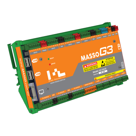
MASSO G3 Operator's manual

MASSO MASSO Documentation
MASSO
Documentation
v5.7 - 26 Sep,2020 www.masso.com.au Page 1 of 383

MASSO MASSO Documentation
How to use this documentation
Using QR codes for viewing interactive content and watching instructional videos.
v5.7 - 26 Sep,2020 www.masso.com.au Page 2 of 383

MASSO MASSO Documentation
Table Of Content
1. MASSO Documentation .................................................................................................. 8
2. Warnings and Cautions .................................................................................................. 9
3. Installing MASSO .......................................................................................................... 10
3.1. Powering MASSO-G3 .................................................................................................. 11
3.2. Powering MASSO-G2 .................................................................................................. 13
3.3. Connecting a Screen ................................................................................................... 14
3.4. Connecting Keyboard & Mouse .................................................................................... 15
3.5. Loading Software to MASSO-G3 .................................................................................. 17
3.6. Loading Software to MASSO-G2 .................................................................................. 18
3.7. Admin and User Passwords ......................................................................................... 20
3.8. Wiring and Calibration ................................................................................................. 23
3.9. Current Software Versions ........................................................................................... 24
4. Machining with MASSO ................................................................................................ 25
4.1. Loading Software to MASSO-G3 .................................................................................. 26
4.2. Loading Software to MASSO-G2 .................................................................................. 27
4.3. Admin and User Passwords ......................................................................................... 29
4.4. Graphical Interface ...................................................................................................... 30
4.4.1. Controller Alarms ..................................................................................................... 37
4.5. Touch Screen Interface
................................................................................................ 39
4.6. Keyboard and Key Shortcuts ........................................................................................ 41
4.6.1. Setting Time ........................................................................................................... 43
4.6.2. Homing the machine ................................................................................................ 44
4.6.3. Rapid/Jog .............................................................................................................. 45
4.6.4. Feed and Speed Override ......................................................................................... 46
4.6.5. MDI command ........................................................................................................ 47
4.6.6. Creating New G-Code Files ....................................................................................... 48
4.6.7. Editing G-Code ....................................................................................................... 49
4.6.8. Resetting Job Counter .............................................................................................. 50
4.7. Loading & Running G-Code ......................................................................................... 51
4.8. Resuming Program or Jump to Line .............................................................................. 52
4.9. Wi-Fi Connectivity ....................................................................................................... 54
4.9.1. MASSO Link Software .............................................................................................. 60
4.10. Calibrating Tools ....................................................................................................... 61
4.10.1. Lathe Tool Calibration Steps .................................................................................... 62
4.10.2. Mill Tool Calibration Steps ....................................................................................... 70
4.11. Work Offsets ............................................................................................................. 73
4.12. Conversational Programming ..................................................................................... 74
4.12.1. Lathe Conversational Wizards .................................................................................. 75
4.12.2. Mill Conversational Wizards ..................................................................................... 81
4.13. Auto Loading G-code ................................................................................................. 86
4.14. Probing
..................................................................................................................... 88
5. Quick Start Guides ........................................................................................................ 91
v5.7 - 26 Sep,2020 www.masso.com.au Page 3 of 383

MASSO MASSO Documentation
5.1. Safe work practices when wiring MASSO ...................................................................... 92
5.2. Setup MASSO Mill
....................................................................................................... 96
5.3. Setup MASSO Plasma .............................................................................................. 107
5.4. Homing Sensor Identify & Connect ............................................................................. 115
6. Supported G-codes ..................................................................................................... 123
6.1. G00 - Rapid Motion ................................................................................................... 124
6.2. G01 - Linear Interpolation Motion
................................................................................ 125
6.3. G02 – Circular Interpolation (Clockwise)
...................................................................... 126
6.4. G03 – Circular Interpolation (Counter Clockwise) ......................................................... 128
6.5. G04 – Dwell .............................................................................................................. 131
6.6. G10 – Set Work Offset Values
.................................................................................... 132
6.7. G17 – XY Plane Selection
.......................................................................................... 133
6.8. G18 – ZX Plane Selection .......................................................................................... 134
6.9. G19 – YZ Plane Selection .......................................................................................... 135
6.10. G20 – Set Machine Units To Inches .......................................................................... 136
6.11. G21 – Set Machine Units To Millimetres .................................................................... 137
6.12. G28 – Return To Machine Home .............................................................................. 138
6.13. G32 – Threading Cycle ............................................................................................ 140
6.14. G38.2 – Straight Probe Cycle ................................................................................... 141
6.15. G53 – Move In Absolute Machine Coordinates
........................................................... 142
6.16. G54 to G59 – Select Work Offset Coordinate System ................................................. 143
6.17. G73 – High Speed Peck Drilling
................................................................................ 144
6.18. G80 – Cancel Modal Motion ..................................................................................... 145
6.19. G81 – Drilling Cycle ................................................................................................. 146
6.20. G82 – Drilling Canned Cycle With Dwell .................................................................... 147
6.21. G83 – Peck Drilling For Deeper Holes ....................................................................... 148
6.22. G90 – Set Distance Mode To Absolute ...................................................................... 149
6.23. G91 – Set Distance Mode To Incremental ................................................................. 150
6.24. G92 – Temporary Work Offset .................................................................................. 151
6.25. G92.1 – Cancel Temporary Work Offset .................................................................... 152
6.26. G93 – Inverse Time Mode ........................................................................................ 153
6.27. G94 – Units Per Minute Mode
................................................................................... 154
6.28. G95 - Feed Per Revolution ....................................................................................... 155
6.29. G96 – Turn on Constant Surface Speed (CSS) .......................................................... 156
6.30. G97 – Turn off Constant Surface Speed (CSS) .......................................................... 157
6.31. G98 – Canned Cycle – Retract Back To The Initial Z .................................................. 158
6.32. G99 – Canned Cycle – Retract Back To R Plane ....................................................... 159
7. Supported M-codes ..................................................................................................... 160
7.1. M00 – Program Stop ................................................................................................. 161
7.2. M01 – Optional Program Stop .................................................................................... 162
7.3. M02 – Program End .................................................................................................. 163
7.4. M03 – Spindle ON (Clockwise) ................................................................................... 164
7.5. M03 – Plasma Torch ON
............................................................................................ 165
7.6. M04 – Spindle ON (Counter Clockwise) ...................................................................... 166
7.7. M05 – Spindle OFF ................................................................................................... 167
v5.7 - 26 Sep,2020 www.masso.com.au Page 4 of 383

MASSO MASSO Documentation
7.8. M05 – Plasma Torch OFF .......................................................................................... 168
7.9. M06 – Tool Change ................................................................................................... 169
7.10. M07 – Turn Mist Coolant On
..................................................................................... 171
7.11. M08 – Turn Flood Coolant On .................................................................................. 172
7.12. M09 – To Turn All Coolant Off .................................................................................. 173
7.13. M10 – Chuck Or Rotary Table Clamp On .................................................................. 174
7.14. M11 – Chuck Or Rotary Table Clamp Off .................................................................. 175
7.15. M30 – End The Program And Rewind ....................................................................... 176
7.16. M62 – Turn On Digital Output Synchronized With Motion
............................................ 177
7.17. M63 – Turn Off Digital Output Synchronized With Motion
............................................ 178
7.18. M64 – Turn On Digital Output Immediately ................................................................ 179
7.19. M65 – Turn Off Digital Output Immediately ................................................................ 180
7.20. M666 – Plasma – Turn THC Function Off .................................................................. 181
7.21. M667 – Plasma – Turn THC Function On .................................................................. 182
7.22. M98 & M99 – Sub Program Call ............................................................................... 183
8. CAM Post Processors ................................................................................................. 185
8.1. Plasma POST Processor Requirements ...................................................................... 186
8.2. Artcam ..................................................................................................................... 188
8.3. BobCAD-CAM
........................................................................................................... 189
8.4. Fusion 360
................................................................................................................ 191
8.5. SheetCAM ................................................................................................................ 192
8.6. Vectric VCarve and Vectric Aspire .............................................................................. 193
9. Setup and Calibration ................................................................................................. 194
9.1. Mounting and Mechanical Data .................................................................................. 195
9.2. E-Stop Wiring ........................................................................................................... 196
9.3. Axis Servo/Stepper examples
..................................................................................... 200
9.3.1. Gecko 203V ......................................................................................................... 203
9.3.2. Gecko G340 ......................................................................................................... 204
9.3.3. Gecko G540 ......................................................................................................... 205
9.3.4. Teknic - ClearPath ................................................................................................. 207
9.3.5. Leadshine MX4660 ................................................................................................ 210
9.3.6. Leadshine CS-D1008 ............................................................................................. 212
9.3.7. Longs Motors ........................................................................................................ 214
9.3.8. CNCdrive - DG4S-16035 ......................................................................................... 215
9.3.9. DMM - Dynamic Motor Motion .................................................................................. 216
9.3.10. VEXTA .............................................................................................................. 217
9.3.11. Viper ................................................................................................................. 218
9.3.12. Mitsubishi - MR-J3 ............................................................................................... 219
9.3.13. PoStep60 ........................................................................................................... 220
9.3.14. Panasonic .......................................................................................................... 221
9.3.15. Automation Technology Inc. ................................................................................... 223
9.3.16. Hiwin ................................................................................................................. 224
9.4. Spindle Control ......................................................................................................... 226
9.5. Spindle VFD examples .............................................................................................. 228
9.5.1. Bosch Rexroth VFD ............................................................................................... 229
v5.7 - 26 Sep,2020 www.masso.com.au Page 5 of 383

MASSO MASSO Documentation
9.5.2. Delta C200 VFD .................................................................................................... 230
9.5.3. Delta MS300 VFD .................................................................................................. 232
9.5.4. Delta VFD-M
......................................................................................................... 234
9.5.5. Yuhuan Huanyang ................................................................................................. 236
9.5.6. Lenze VFD ........................................................................................................... 238
9.5.7. Hitachi VFD .......................................................................................................... 239
9.5.8. TECO Westinghouse VFD ....................................................................................... 243
9.5.9. Schneider Altivar 18 ............................................................................................... 245
9.5.10. Mitsubishi FR-D720S-100 ...................................................................................... 246
9.6. Door Input ................................................................................................................ 248
9.7. Setting default units to mm or inches .......................................................................... 249
9.8. Axis Calibration ......................................................................................................... 250
9.9. Axis Calibration Wizard .............................................................................................. 253
9.10. Backlash Compensation .......................................................................................... 256
9.11. Slave Axis
............................................................................................................... 257
9.12. Homing / Home Inputs ............................................................................................. 258
9.13. Soft & Hard Limits ................................................................................................... 264
9.14. List of Configurable Inputs
........................................................................................ 265
9.15. List of Configurable Outputs ..................................................................................... 267
9.16. TTL Outputs
............................................................................................................ 268
9.17. Controlling Relays ................................................................................................... 269
9.18. MPG Pendant ......................................................................................................... 270
9.19. Tower Lights ........................................................................................................... 273
9.20. Installing or Replacing Backup Battery ...................................................................... 274
9.21. User Account Settings ............................................................................................. 275
9.22. MASSO Homing Sensor .......................................................................................... 276
9.23. MASSO Optical Encoder
.......................................................................................... 278
9.24. MASSO Relay Module ............................................................................................. 280
9.25. MASSO G2 Drive and Relay wiring ........................................................................... 286
9.26. Lubrication .............................................................................................................. 295
9.27. MASSO G2 Replacing Damaged Optocouplers ......................................................... 296
9.28. Spindle RPM Encoder
.............................................................................................. 301
9.28.1. Upgrading the Spindle encoder on MASSO G2 .......................................................... 304
10. Save & Load Settings ............................................................................................... 306
11. Touch Probe .............................................................................................................. 308
12. Tool Setter / Touch Plate .......................................................................................... 312
13. Automatic Tool Length Calibration ......................................................................... 314
14. Tool Changers ........................................................................................................... 316
14.1. Mill Tool Changers .................................................................................................. 317
14.1.1. Manual Tool Changer ........................................................................................... 318
14.1.2. Linear Tool Changer (Type 1) ................................................................................. 320
14.1.3. Linear Tool Changer (Type 2) ................................................................................. 325
14.1.4. Umbrella Tool Changer ......................................................................................... 330
14.2. Lathe Tool Changers ............................................................................................... 334
14.2.1. Manual Tool Change ............................................................................................ 335
v5.7 - 26 Sep,2020 www.masso.com.au Page 6 of 383

MASSO MASSO Documentation
14.2.2. Linear - Gang Type Setup ...................................................................................... 336
14.2.3. 4 Station Turret
.................................................................................................... 337
14.2.4. EMCO PC55 Turn ................................................................................................ 340
14.2.5. 4 Bit Digital Signal Output Turret ............................................................................. 342
14.2.6. Hercus PC200 - 8 Tool Turret ................................................................................. 345
14.2.7. Pragati BTP-63, BTP-80, BTP-100, BTP-125 ............................................................. 347
14.2.8. EMCOturn 120 .................................................................................................... 349
15. Plasma - Torch Height Control ................................................................................ 352
15.1. Proma Compact THC 150 ........................................................................................ 353
15.2. Hypertherm 45, 65 & 85 ........................................................................................... 355
15.3. Torch Touch (floating head) Signal ........................................................................... 356
15.4. Torch Breakaway Signal .......................................................................................... 358
15.5. How THC works ...................................................................................................... 359
16. OEM Logo & Details .................................................................................................. 367
17. Sherline Mills and Lathes ......................................................................................... 369
17.1. Wiring & Setup ........................................................................................................ 371
18. 3DTEK Routers .......................................................................................................... 373
19. CANCAM Routers ...................................................................................................... 374
20. Forums & Email Support .......................................................................................... 375
21. Reporting Bugs & Issues ......................................................................................... 376
22. Payment ..................................................................................................................... 377
23. Shipping & Delivery .................................................................................................. 379
24. Warranty ..................................................................................................................... 381
25. Returns ....................................................................................................................... 382
v5.7 - 26 Sep,2020 www.masso.com.au Page 7 of 383

MASSO MASSO Documentation
1. MASSO Documentation
Welcome to MASSO documentation. You can quickly search for information using the search bar on the top-
right.
We have prepared the following quick links to help you find the right information for your project.
Installing MASSO
Current Software Versions
Machining with MASSO
Getting Support
Original Equipment Manufacturer (OEM)
Purchasing
v5.7 - 26 Sep,2020 www.masso.com.au Page 8 of 383

MASSO MASSO Documentation
2. Warnings and Cautions
WARNING: Indicates circumstances or practices that can lead to personal injury as well as
damage to the controller, the machine, or other equipment.
CAUTION: Indicates circumstances or practices that can lead to damage to the controller or other
equipment.
INFORMATION: Indicates important information.
v5.7 - 26 Sep,2020 www.masso.com.au Page 9 of 383

MASSO MASSO Documentation
3. Installing MASSO
v5.7 - 26 Sep,2020 www.masso.com.au Page 10 of 383

MASSO MASSO Documentation
3.1. Powering MASSO-G3
The MASSO power supply connector is located at the top-right corner of the controller as seen in the picture
below. MASSO requires a power supply between 12 and 24 VDC with minimum of 1.5 Amps output.
MASSO will power on instantly once power is connected.
WARNING: The installation of a 1 amp fuse between your Power Supply and MASSO is required
to protect against an accidental short circuit of the auxiliary power connectors on MASSO, such an
event can damage the controller beyond repair.
INFORMATION: There are multiple Power (Red coloured) and Ground (Black coloured)
provided on the controller and can be used to easily wire drives, sensors and switches.
v5.7 - 26 Sep,2020 www.masso.com.au Page 11 of 383

MASSO MASSO Documentation
Some examples:
The Power terminals can be used to provide voltage to sensors or switches for machine homing.
The Ground terminals can be used to wire common ground signals between stepper or servo motor
drives.
CAUTION: Power and Ground terminals provided on the controller are only to be used for very
low current signals. Connecting high current loads can damage the controller beyond repair.
v5.7 - 26 Sep,2020 www.masso.com.au Page 12 of 383

MASSO MASSO Documentation
3.2. Powering MASSO-G2
The MASSO power supply connector is located at the top-right corner of the controller as seen in the picture
below. MASSO requires a power supply between 12 and 24 VDC with minimum of 1.5 Amps output.
MASSO will power on instantly once power is connected.
v5.7 - 26 Sep,2020 www.masso.com.au Page 13 of 383

MASSO MASSO Documentation
3.3. Connecting a Screen
MASSO uses a standard 15 pin female VGA connector (1024 x 768 screen resolution)
INFORMATION: If the monitor only supports HDMI input then a simple VGA to HDMI converter
can be used.
INFORMATION: The display is a 4:3 aspect ratio and will look distorted when displayed as 16:9 on
a widescreen monitor. Monitors have settings to set display ratio, please refer to your monitor's
user manual.
INFORMATION: For information about connecting touch screens, please use the below link.
Touch Screen Interface
v5.7 - 26 Sep,2020 www.masso.com.au Page 14 of 383

MASSO MASSO Documentation
3.4. Connecting Keyboard & Mouse
Standard USB Keyboard & Mouse can be connected to MASSO, both wired and wireless devices are
supported.
INFORMATION: MASSO G3 has 4 USB ports and MASSO G2 has 2 USB ports. If more USB
ports are required then a USB HUB can also be connected.
INFORMATION: MASSO supports English (QWERTY) and German (QWERTZ) keyboards. Select
your keyboard type under General Settings.
CAUTION: Avoid using unbranded Keyboard and Mouse as they are known to cause issues.
v5.7 - 26 Sep,2020 www.masso.com.au Page 15 of 383

MASSO MASSO Documentation
v5.7 - 26 Sep,2020 www.masso.com.au Page 16 of 383

MASSO MASSO Documentation
3.5. Loading Software to MASSO-G3
Regular updates are released to add more features to the units. Custom software's are also released for
special client requirements. The software upgrade process can be easily performed on site by following the
instructions below:
Scan the QR code to watch the MASSO video tutorial on YouTube
Or, Click here to view the video
Information: Avoid using unbranded USB Flash drives as these are known to give issues with
software install and upgrades
Information: It is advisable to make a backup of your settings before upgrading your software.
Information: Summary of install and upgrade process
Ensure your Flash drive is formatted to Fat32
Create a folder called MASSO on the flash drive and copy the software file emailed to you into this
folder.
On powering Masso immediately press the F1 key repeatedly until the Masso software load screen
appears. If the software load screen does not appear re-power Masso and start again.
Select the desired software from the list in the software load screen using the up/down arrow keys
and press the enter key on your keyboard.
After the software has finished loading press the ESC key and your Masso will restart with your new
software.
v5.7 - 26 Sep,2020 www.masso.com.au Page 17 of 383

MASSO MASSO Documentation
3.6. Loading Software to MASSO-G2
Regular updates are released to add more features to the units. Custom software's are also released for
special client requirements. The software up-gradation process can be easily performed on site by following
the instructions below:
Scan the QR code to watch the MASSO video tutorial on YouTube
Or, Click here to view the video
Information: Avoid using unbranded USB Flash drives as these are known to give issues with
software install and upgrades
Information: It is advisable to make a backup of your settings before upgrading your software.
NOTE: For the below example the controller serial number will be 5A-660
WARNING: Check that while copying file from email the file name is not renamed and is exactly
"00000660.HTG"
Check that the file name matches the serial number of the controller.
Connect a USB flash drive to your PC/MAC and make sure it's been formatted in FAT or FAT32
format.
v5.7 - 26 Sep,2020 www.masso.com.au Page 18 of 383

MASSO MASSO Documentation
Copy all the files received in the software update email including "00000660.HTG" and Data1.HTG
file to the USB flash drive.
When copying the files to the USB flash drive, please make sure that your email software does not
download the files as ZIP file.
Power off the controller.
NOTE: Make sure that there is nothing connected on the PlayStation connector on the MASSO
Insert the USB flash drive into the controller's USB flash drive connector and DO NOT connect a
USB hub.
Power up the controller and a progress bar will be displayed on the screen showing the upgrade
status.
Once the progress bar shows 100%, the upgrade process is finished, please power cycle the unit.
v5.7 - 26 Sep,2020 www.masso.com.au Page 19 of 383

MASSO MASSO Documentation
3.7. Admin and User Passwords
By default the system password is set to "HTG" (in capital letters) for both Admin and User logins.
INFORMATION: When the controller is powered up, Caps Key is enabled by default.
Scan the QR code to watch the MASSO video tutorial on YouTube
Or, Click here to view the video
INFORMATION: If want to lock Masso to prevent unauthorized use, Press CTRL + L and you will
be prompted to re-enter the User and Admin Passwords.
Changing the User or Admin Password
To change the User or Admin password Click on the Change Password in the Login box.
Enter the current Password and press enter. Default Password is "HTG"
Enter the new password up to 5 characters long in the New Password box. (Passwords are case
sensitive)
v5.7 - 26 Sep,2020 www.masso.com.au Page 20 of 383
This manual suits for next models
1
Table of contents
Other MASSO Controllers manuals