1Einsatzmöglichkeiten
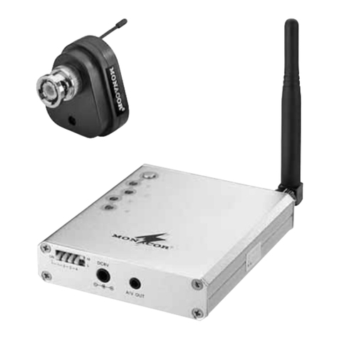
Der Sender AV-100TX dient in Verbindung mit einem
2,4-GHz-Empfänger der Serie „AV-...R“ von MONACOR
zur drahtlosen Übertragung von Videosignalen. Zum
Aufbau einer drahtlosen Video-Überwachungsanlage
werden zusätzlich nur noch eine Videokamera und ein
Monitor benötigt.
Die Übertragungsreichweite hängt stark von den ört-
lichen Gegebenheiten ab. Bei Sichtverbindung zwi-
schen Sender und Empfänger kann sie bis zu 300 m
betragen. In Gebäuden reduziert sich die Reichweite
jedoch durch die Wände und Decken je nach deren
Beschaffenheit auf ca. 30 m. Durch die Verwendung
einer gewinnbringenden Antenne am Empfänger kann
die Reichweite jedoch um ein Mehrfaches erhöht
werden.
1.1 Zulassung
Die Zulassung für den Sender ist nach der R + TTE-
Richtlinie (Radio and Telecommunication Technical
Equipment) in den Staaten der Europäischen Union
gültig. Für den Betrieb in Staaten außerhalb der EU fra-
gen Sie bitte Ihren Fachhändler oder die MONACOR-
Niederlassung des entsprechenden Landes.
2Hinweise für den sicheren Gebrauch
Dieser Sender entspricht der EU-Richtlinie 89/336/
EWG für elektromagnetische Verträglichkeit.
●Der Sender ist nur zur Verwendung im Innenbereich
geeignet. Schützen Sie ihn vor Feuchtigkeit und
extremen Temperaturen (zulässiger Einsatztempera-
turbereich:
-
10 °C bis +55 °C).
●Decken Sie die Lüftungsöffnungen des Gehäuses
nicht ab und stecken Sie keine Gegenstände hin-
durch. Der Sender kann dadurch beschädigt werden.
●Verwenden Sie für die Reinigung nur ein trockenes,
weiches Tuch, auf keinen Fall Chemikalien oder
Wasser.
●Wird der Sender zweckentfremdet, falsch ange-
schlossen oder nicht fachgerecht repariert, kann für
eventuelle Schäden keine Haftung übernommen
werden.
●Soll der Sender endgültig aus dem Betrieb genom-
men werden, übergeben Sie ihn zur umweltgerech-
ten Entsorgung einem örtlichen Recyclingbetrieb.
3Inbetriebnahme
3.1 Platzierung von Sender und Empfänger
Erfahrungen aus der Praxis zeigen, dass ein optimaler
Empfang bei einer Aufstellung in einer Höhe von min-
destens 1,5 m bis 2 m über dem Boden erreicht wird.
Vor der endgültigen Montage sollte ein Probebetrieb
erfolgen, da bereits durch Verschieben des Senders
und des Empfängers um nur einige Zentimeter sich die
Übertragungsqualität erheblich ändern kann.
3.2 Montage
Zur Montage auf eine Halterung oder auf ein Stativ wird
eine 6,3-mm-Gewindebuchse (1/4") mitgeliefert. Diese
kann mit einem handelsüblichen Kunststoffkleber am
Gehäuse des Senders befestigt werden.
3.3 Kanalwahl
Die Funkübertragung erfolgt im 2,4-GHz-Bereich, der
vom Hersteller in fünf Kanäle mit einem Abstand von
14 MHz aufgeteilt wurde. Maximal können gleichzeitig
drei Kanäle benutzt werden (Kanal 1, 3 und 5), weil
zwei direkt nebeneinander liegende Kanäle sich stören.
Es wird folgende Kanalwahl empfohlen:
bei zwei Kameras: Kanal 1 und 5
bei drei Kameras: Kanal 1, 3 und 5
Den gewünschten Sendekanal mit den DIP-Schaltern
auf der Gehäuserückseite einstellen:
Am Empfänger den gleichen Kanal einstellen.
3.4 Anschluss einer Kamera bzw. Signalquelle
Es können sowohl Schwarzweiß- als auch Farbkameras
angeschlossen werden. Den Videoausgang der Kamera
bzw. der Signalquelle über ein abgeschirmtes Kabel mit
der Cinch-Buchse „video“ verbinden. Der Pegel des
Videosignals muss normgerecht 1 Vss betragen.
3.5 Stromversorgung
Zur Stromversorgung wird ein stabilisiertes 12-V-Netz-
gerät mit einem Ausgangsstrom von mindestens
110mAbenötigt, z. B. PS-362ST von MONACOR.
1) Bei Netzgeräten mit variabler Ausgangsspannung
diese auf 12 V (±0,5 V) einstellen.
2) Die Stromversorgung über einen Kleinspannungs-
stecker 5,5/2,1 mm (Außen-/Innendurchmesser)
an die Buchse „12 V stab.“ anschließen. Dabei
unbedingt die Polung beachten: den Pluspol an
den Innenkontakt des Steckers anlegen.
3) Nach dem Anlegen der Betriebsspannung ist der
Sender betriebsbereit.
4Technische Daten
Zulassungsnummer: . . . . . BZT G 750 816 J
Sendefrequenz: . . . . . . . . . Kanal 1 2,4145 GHz
Kanal 2 2,4285 GHz
Kanal 3 2,4425 GHz
Kanal 4 2,4565 GHz
Kanal 5 2,4705 GHz
Sendeleistung: . . . . . . . . . 10 mW (EIRP)
Antenne: . . . . . . . . . . . . . . Rundstrahlantenne
Reichweite
bei Sichtverbindung: . . . bis 300 m
in Gebäuden: . . . . . . . . bis 30 m
Video
Eingangspegel: . . . . . . . 1 Vss/75 Ω
Bandbreite: . . . . . . . . . . 30 Hz – 5 MHz
Modulation: . . . . . . . . . . frequenzmoduliert F3F
Betriebsspannung: . . . . . . 12 V ±0,5 V/110 mA
Einsatztemperatur: . . . . . .
-
10 °C bis +55 °C
Abmessungen
ohne Antenne: . . . . . . . . . . 54 x 54 x 35 mm
Gewicht: . . . . . . . . . . . . . . 60 g
Laut Angaben des Herstellers.
Änderungen vorbehalten.
FRANÇAIS
DEUTSCH
1Possibilités d’utilisation
L’émetteur AV-100TX est utilisé, combiné à un récep-
teur 2.4 GHz de la série “AV-...R” de MONACOR, pour
la transmission sans fil de signaux vidéo. Pour conce-
voir une installation de surveillance vidéo sans fil, une
caméra vidéo et un moniteur uniquement sont égale-
ment nécessaires.
La portée de transmission dépend grandement de la
configuration des lieux. Lorsqu’il n’y a pas d’obstacle
entre l’émetteur et le récepteur, la portée peut atteindre
300 m; dans des bâtiments, selon la nature des murs et
plafonds, la portée est réduite à 30 m environ. Elle peut
être augmentée plusieurs fois si on utilise une antenne
prévue pour augmenter le gain sur le récepteur.
1.1 Autorisation
L’autorisation d’utilisation pour l’émetteur est valable
dans les pays de l’Union Européenne selon la directive
R+TTE (Radio and Telecomunication Technical Equip-
ment). Dans le cadre d’une utilisation hors de l’Union
Européenne, contactez votre revendeur ou la succur-
sale MONACOR du pays où l’appareil va fonctionner.
2Conseils d’utilisation et de sécurité
L’émetteur répond à la norme européenne 89/336/CEE
relative à la compatibilité électromagnétique.
●L’émetteur n’est conçu que pour une utilisation en
intérieur. Protégez-le de l’humidité et des températures
extrêmes (plage de température de fonctionnement
autorisée :
-
10 °C à +55 °C).
●Ne couvrez pas les ouïes de ventilation du boîtier, ne
faites pas tomber d’objets à travers. L’émetteur pour-
rait être endommagé.
●Pour nettoyer l’appareil, utilisez uniquement un chif-
fon sec et doux, en aucun cas de produits chimiques
ou d’eau.
●Nous déclinons toute responsabilité en cas de dom-
mage si l’émetteur est utilisé dans un but autre que
celui pour lequel il a été conçu, s’il n’est pas correcte-
ment branché, ou réparé par une personne habilitée.
●Lorsque l’émetteur est définitivement retiré du marché,
vous devez le déposer dans une usine de recyclage
de proximité pour contribuer à son élimination non
polluante.
3Fonctionnement
3.1 Placement de l’émetteur et du récepteur
L’expérience montre que la réception est optimale pour
un positionnement des appareils à une hauteur de
1,5 m à 2 m au moins au-dessus du sol. Avant le mon-
tage définitif, il est conseillé d’effectuer un test car un
déplacement de l’émetteur et du récepteur de quelques
centimètres uniquement peut modifier considérable-
ment la qualité de transmission.
3.2 Montage
Pour le montage sur un support ou un pied, une prise
filetée de 6,3 mm (1/4") est livrée. Elle peut être fixée sur
le boîtier de l’émetteur avec une colle usuelle.
3.3 Sélection du canal
La transmission sans fil s’effectue dans la plage 2,4 GHz,
divisée en 5 canaux par le fabricant avec un intervalle de
14 MHz. On peut utiliser simultanément 3 canaux au plus
(canal 1, 3 et 5) car deux canaux immédiatement proches
génèrent entre eux des interférences : nous recomman-
dons la sélection suivante :
pour deux caméras : canal 1 et 5
pour trois caméras: canal 1, 3, 5
Réglez le canal d’émission avec les interrupteurs DIP
sur la face arrière du boîtier.
Réglez le même canal sur le récepteur.
3.4 Branchement d’une caméra ou d’une source
de signal
Il est possible de brancher des caméras noir et blanc ou
couleur. Reliez la sortie vidéo de la caméra ou de la
source vidéo via un câble blindé à la prise RCA “video” ;
le niveau du signal vidéo doit, selon les normes, être de
1 Vcc.
3.5 Alimentation
Pour l’alimentation, une alimentation stabilisée de 12 V
avec un courant de sortie de 110 mA minimum est
nécessaire, par exemple PS-362ST de MONACOR.
1) Dans le cas d’appareils avec une tension de sortie
variable, réglez-la sur 12 V (±0,5 V).
2) Reliez l’alimentation via un adaptateur 5,5/2,1 mm
(diamètre extérieur/diamètre intérieur) à la prise
“12 V stab.” Respectez impérativement la polarité :
le pôle plus doit être au contact intérieur de la fiche.
3) Une fois la tension de fonctionnement appliquée,
l’émetteur est prêt à fonctionner.
4Caractéristiques techniques
Numéro d’identification : . . BZT G 750 816 J
Fréquence d’émission : . . . canal 1 2,4145 GHz
canal 2 2,4285 GHz
canal 3 2,4425 GHz
canal 4 2,4565 GHz
canal 5 2,4705 GHz
Puissance d’émission : . . . 10 mW (EIRP)
Antenne : . . . . . . . . . . . . . . antenne omnidirectionnelle
Portée
en l’absence
d’obstacles : . . . . . . . . . jusqu’à 300 m
dans des bâtiments : . . . jusqu’à 30 m
Vidéo
Niveau d’entrée : . . . . . . 1 Vcc/75 Ω
Largeur de bande : . . . . 30 Hz – 5 MHz
Modulation : . . . . . . . . . modulation de fréquence
F3F
Tension de fonctionnement : 12 V ±0,5 V/110 mA
Température
de fonctionnement : . . . . . .
-
10 °C à +55 °C
Dimensions sans antenne : 54 x 54 x 35 mm
Poids : . . . . . . . . . . . . . . . . 60 g
D’après les données du constructeur.
Tout droit de modification réservé.
