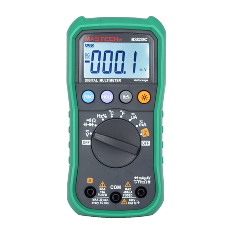
4.15 Measuring DC Millivoltage
4.15.1 Plug the black test lead into the COM jack and
the red test lead into the V jack.
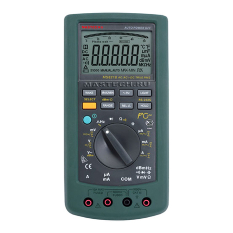
4.15.2 Set the rotary selector to the mV range position.
4.15.3 Press the "SELECT" button to switch to DC
measurement. Then press the “RANGE” button
to choose the auto range or manual range mode.
4.15.4 Connect the test leads to the voltage source or
load terminals for measurement.
4.15.5 Take the reading on the main indicator of the LCD.
The polarity symbol denotes the polarity of the end
1) When the input is open, unsteady readings may
appear. This is normal because the meter is highly
sensitive. When the test leads contact the circuit,
the true reading will be shown.
2) At the manual range mode, when only 'OL' or '-OL' is
shown on the LCD, it means the measurement has
exceeded the range. A higher range should be selected.
3) At the manual range mode, when the scale of the
value to be measured is unknown beforehand, set
the rotary selector to the highest range.
4.16 Measuring AC Millivoltage
4.16.1 Plug the black test lead into the COM jack and
the red test lead into the V jack.
4.16.2 Set the rotary selector to the mV range position.
4.16.3 Press the "SELECT" button to switch to AC
measurement. Then press the “RANGE” button
to choose the auto range or manual range mode.
4.16.4 Connect the test leads to the voltage source or
load terminals for measurement.
4.16.5 Take the reading on the main indicator of the LCD.
1) When the input is open, unsteady readings may
appear. This is normal because the meter is highly
sensitive. When the test leads contact the circuit,
the true reading will be shown.
2) At the manual range mode, when only 'OL' or '-OL' is
shown on the LCD, it means the measurement has
exceeded the range. A higher range should be selected.
3) At the manual range mode, when the scale of the
value to be measured is unknown beforehand, set
the rotary selector to the highest range.
4.17 Measuring DC Current
Beware of Electrocution.
Turn off the power of the circuit to be
measured before connecting the meter to
the circuit.
4.17.1 Plug the black test lead into the COM jack. When
the current to be measured is under 400mA,
plug the red test lead into the mA jack; when the
current to be measured is over 400mA but under
10A, plug the red test lead into the 10A jack.
4.17.2 Set the rotary selector to the A range position.
4.17.3 Press the "SELECT" button to switch to DC
measurement. Then press the “RANGE” button
to choose the auto range or manual range mode.
4.17.4 Connect the test leads to the circuit for
measurement.
4.17.5 Take the reading on the main indicator of the
LCD. The polarity symbol denotes the polarity
of the end connected by the red test lead.