Master cool 53376 User manual

1www.mastercool.com
Deutsch
Français
Español
Italiano
Nederlands
English
Portuguese
OPERATING INSTRUCTIONS
R134a Visual Inspection Sight Glass
R1234yf Visual Inspection Sight Glass
53376, 53376-YF,
53377, 53377-YF
BEDIENUNGSANLEITUNG
R134a Schauglas f. Sichtprüfung
R1234yf Schauglas f. Sichtprüfung
53376, 53376-YF,
53377, 53377-YF
MANUEL D’OPÉRATION
Voyant D’Inspection pour R134a
Voyant D’Inspection pour R1234yf
53376, 53376-YF,
53377, 53377-YF
INSTRUCCIONES DE OPERACION
R134a Cápsula de Vidrio para
Inspección Visual
R1234yf Cápsula de Vidrio para
Inspección Visual
53376, 53376-YF,
53377, 53377-YF
ISTRUZIONI PER L’USO
Unità di Ispezione Visiva per R134a
Unità di Ispezione Visiva per R1234yf
53376, 53376-YF,
53377, 53377-YF
HANDLEIDING
R134a Kijkglas voor Visuele Inspectie
R1234yf Kijkglas voor Visuele Inspectie
53376, 53376-YF,
53377, 53377-YF
MANUAL DE OPERAÇÃO
R134a Pirex de Inspeção Visual
R1234yf Pirex de Inspeção Visual
53376, 53376-YF,
53377, 53377-YF

2www.mastercool.com
English
WARNING
• WEAR GOGGLES!!
• AVOID CONTACT WITH REFRIGERANT
PREPARING THE SIGHT GLASS
When Using Vacuum from a Recycling Machine
1. Connect both the red and the blue hoses supplied to the corresponding end of the sight glass.
2. Connect both the red and blue coupler to the corresponding end of the hose. Close each coupler by turning the knob
counterclockwise (manual couplers only.) Connect the blue low side hose and coupler from your RRR machine to the
low side fitting on the blue side of the sight glass.
3. Open both ball valves on each side of the sight glass.
4. Run a vacuum for 3 minutes from the control panel on your RRR machine. This will remove any atmosphere from the
sight glass to allow for an accurate test.
5. Disconnect the low side RRR machine coupler from the sight glass when vacuum run time is completed.
6. Go to using the sight glass section.
When Using Vacuum from a Vacuum Pump
1. Close both ball valves. Connect the red hose supplied to the red side of the sight glass. Attach the high side coupler
to the hose and close the coupler by turning the knob counterclockwise (manual couplers only.)
2. Connect the low side coupler to the blue hose and close the coupler by turning the knob counterclockwise (manual
couplers only.)
3. Connect the low side coupler to the service port on the sight glass. Open the coupler by turning the knob clockwise
(manual couplers only.)
4. Connect the other end of the blue hose to your vacuum pump.
5. Open the red high side ball valve, leave the blue low side ball valve closed.
6. Run your vacuum pump for 3 minutes. This will remove any atmosphere from the sight glass to allow for an accurate
test.
7. Disconnect the blue hose from the vacuum pump when vacuum time is completed. Close the low side coupler by
turning the knob counterclockwise (manual couplers only.) Disconnect the blue coupler from the sight glass. The
fittings on the blue hose and coupler both have auto shutoff’s which will maintain the vacuum created in the sight
glass and hoses.
8. Connect the blue hose to the blue side of the sight glass.
USING THE SIGHT GLASS
1. Close both ball valves on the sight glass.
2. Connect the red coupler to the high side of the AC system. Open the coupler by turning the knob clockwise (manual
couplers only.)
3. Connect the blue coupler to the low side of the AC system. Open the coupler by turning the knob clockwise (manual
couplers only.)
4. Start the vehicle and turn the AC system on.
5. Hold the sight glass in a vertical position with the red hose down.
6. SLOWLY open the red side ball valve.
7. When the sight glass is ¼ full of liquid refrigerant, close the red side ball valve (be sure the blue side ball valve is still
closed as well).
8. Allow the refrigerant to stabilize.
9. Check the color of the refrigerant using the chart below. Check for any debris in the refrigerant.
CLEARING THE SIGHT GLASS OF REFRIGERANT
1. To put the refrigerant back into the AC system, first turn off the AC system and vehicle.
2. Close the high side coupler by turning the knob counterclockwise (manual couplers only.) Remove the red coupler
from the high side of the vehicle.

3www.mastercool.com
3. Turn on the vehicle and the AC system.
4. Open the red high side ball valve on the sight glass.
5. SLOWLY OPEN THE BLUE LOW SIDE BALL VALVE ON THE SIGHT GLASS.
6. Wait for 1 minute after the liquid refrigerant is removed from the sight glass. This allows any refrigerant in the blue
hose to enter the AC system.
7. Close the low side coupler by turning the knob counterclockwise (manual couplers only.) Remove the blue coupler
from the low side.
8. Turn off the AC system and the vehicle.
POSSIBLE CONTAMINANTS THAT CAN BE SEEN IN THE INSPECTION GLASS INCLUDE:
CARBONIZED OIL PARTICLES When oil is exposed to high temperatures
RUBBER PARTICLES Aggressive acids penetrating rubber parts
MOISTURE Leaks, incorrect or insufficient vacuum or wrong/inferior quality additives
METAL SILVER/CHIPS Compressor seizure or metal parts abrasion
AGGRESSIVE ACIDS Chemical reaction between moisture and refrigerant/oil or incorrect oil mixtures
VARIOUS PARTICLES Soiled compounds created from using poor quality or incorrect additives such as leak
stop agents, UV dye or oil mixture composites
UNACCEPTABLE CONDITIONS
These conditions when viewed in the inspection glass are an indication of serious system/component issues
DARK GREEN
Excessive UV dye in the system
RUBBER/PLASTIC COMPOUNDS
Aged seals, strong additives reacting
with seals and hoses, receiver dryer
failure or too much dryer wear
RED/ORANGE
Excessive red leak tracing dye in the
system
BUBBLE/PEARLS
Moisture in the system, contamination
caused by insufficient quality additives,
incorrect vacuum pulled during
previous services
LIGHT BROWN
System or compressor subjected to
overheating
GEL-LIKE, CRYSTALLIZED TEXTURE
Insufficient quality leak stop agents
reacting with refrigerant/oil or UV dye,
no/incorrect vacuum pulled before leak
stop applications
DARK BROWN OR BLACK
System or compressor subjected to
excessive overheating
CREAM/UNCLEAR TEXTURE
Aggressive flushing agent residues
reacting with aluminum and teflon
coating on the compressor’s parts,
incorrect flushing and vacuum pulled
after flushing
METAL CHIPS/PARTICLES
Compressor seizure caused by oil
starvation or incorrect lubrication
IMBALANCED LIQUIDS MIXTURE
Application of universal/incorrect oils,
unbalanced, non-homogeneous mixture
of various oils
ACCEPTABLE CONDITIONS
These conditions when viewed in the inspection glass are an indication that no issues are present
ACCEPTABLE CONDITION
Pure mix of refrigerant and lubricant
ACCEPTABLE CONDITION
Appropriate mix of refrigerant, lubricant
and UV dye

4www.mastercool.com
PARTS LIST
Item # Part # Description
1. 53375 Refrigerant Oil Visual Inspection Sight Glass
2. 82274 Low Side, 1/4” (7/16”-20) x 13 mm Retrofit Adapter
3. 53376-601 60” Blue R134a Charging Hose
4. 53376-603 60” Red R134a Charging Hose
5. 66234 R134a High Side Quick Coupler
6. 66334 R134a Low Side Quick Coupler
7. 84274 1/4 fl-f x 17 mm-m R1234yf Adapter with Valve Core
8. 53376-601YF 60” Blue R1234yf Charging Hose
9. 53376-603YF 60” Red R1234yf Charging Hose
10. 67434 R1234yf High Side Quick Coupler
11. 67534 R1234yf Low Side Quick Coupler
12. 82834 R134a High Side Manual Coupler
13. 82934 R134a Low Side Manual Coupler
14. 83834 R1234yf High Side Manual Coupler with Extended Disconnect Sleeve
15. 83934 R1234yf Low Side Manual Coupler with Extended Disconnect Sleeve
1
7
10 11
56
3
4
14 15
12 13
9
8
WARNING: This product can expose you to chemicals including Di (2-ethylhexyl) phthalate, lead and lead compounds,
which are known to the State of California to cause cancer and birth defects or other reproductive harm. For more
information go to www.P65Warnings.ca.gov
2

5www.mastercool.com
WARNUNG
• TRAGEN SIE EINE SCHUTZBRILLE!
• VERMEIDEN SIE KONTAKT MIT KÄLTEMITTEL
VORBEREITUNG DES SCHAUGLASES
Bei Verwendung eines Vakuums aus einer Recycling-Maschine
1. Schließen Sie die mitgelieferten roten und blauen Schläuche an die ent-sprechende Seite des Schauglases an.
2. Schließen Sie die rote und blaue Kopplung an die entsprechende Seite des Schlauches an. Schließen Sie jede
Kopplung durch Drehen des Knopfes gegen den Uhrzeigersinn (nur bei manuellen Kopplungen). Schließen Sie den
blauen Niederdruck-Schlauch und die Kopplung aus Ihrer RRR-Maschine an die Niederdruck-Armatur auf der blauen
Seite des Schauglases an.
3. Öffnen Sie die beiden Kugelhähne auf jeder Seite des Schauglases.
4. Lassen Sie vom Bedienpult aus 3 Minuten lang ein Vakuum auf Ihrer RRR-Maschine laufen. Dadurch wird jegliche
Atmosphäre aus dem Schauglas entfernt, um eine akkurate Prüfung zu ermöglichen.
5. Trennen Sie die Niederdruck-Kopplung der RRR-Maschine vom Schau-glas, wenn die Vakuumlaufzeit abgeschlossen
ist.
6. Gehen Sie zum Abschnitt „Verwendung des Schauglases“.
Bei Verwendung eines Vakuums aus einer Vakuumpumpe
1. Schließen Sie beide Kugelhähne. Schließen Sie den mitgelieferten ro-ten Schlauch an die rote Seite des Schauglases
an. Bringen Sie die Hochdruck-Kopplung am Schlauch an und schließen Sie die Kopplung durch Drehen des Knopfes
gegen den Uhrzeiger-sinn (nur bei manuellen Kopplungen).
2. Bringen Sie die Niederdruck-Kopplung am blauen Schlauch an und schließen Sie die Kopplung durch Drehen des
Knopfes gegen den Uhr-zeigersinn (nur bei manuellen Kopplungen).
3. Schließen Sie die Niederdruck-Kopplung an den Service-Anschluss des Schauglases an. Öffnen Sie die Kopplung
durch Drehen des Knopfes im Uhrzeigersinn (nur bei manuellen Kopplungen).
4. Schließen Sie die andere Seite des blauen Schlauches an Ihre Vakuum-pumpe an.
5. Öffnen Sie den roten Hochdruck-Kugelhahn, lassen Sie den blauen Niederdruck-Kugelhahn geschlossen.
6. Lassen Sie Ihre Vakuumpumpe 3 Minuten lang laufen. Dadurch wird jegliche Atmosphäre aus dem Schauglas
entfernt, um eine akkurate Prüfung zu ermöglichen.
7. Trennen Sie den blauen Schlauch von der Vakuumpumpe, wenn die Vakuumdauer abgeschlossen ist. Schließen Sie
die Niederdruck-Kopplung durch Drehen des Knopfes gegen den Uhrzeigersinn (nur bei manuellen Kopplungen).
Trennen Sie die blaue Kopplung vom Schau-glas. Die Armaturen am blauen Schlauch und der Kopplung haben bei-de
automatische Abschaltungen, welche das erzeugte Vakuum im Schauglas und den Schläuchen aufrechterhalten.
8. Schließen Sie den blauen Schlauch an die blaue Seite des Schauglases an.
VERWENDUNG DES SCHAUGLASES
1. Schließen Sie beide Kugelhähne am Schauglas.
2. Schießen Sie die rote Kopplung an den Hochdruck-Anschluss der Klimaanlage an. Öffnen Sie die Kopp-lung durch
Drehen des Knopfes im Uhrzeigersinn (nur bei manuellen Kopplungen).
3. Schließen Sie die blaue Kopplung an den Niederdruck-Anschluss der Klimaanlage an. Öffnen Sie die Kopplung durch
Drehen des Knopfes im Uhrzeigersinn (nur bei manuellen Kopplungen).
4. Starten Sie das Fahrzeug und schalten Sie die Klimaanlage ein.
5. Halten Sie das Schauglas in einer vertikalen Position, mit dem roten Schlauch unten.
6. Öffnen Sie LANGSAM den Kugelhahn auf der roten Seite.
7. Wenn das Schauglas zu ¼ mit flüssigem Kältemittel gefüllt ist, schließen Sie den Kugelhahn der roten Seite (stellen
Sie sicher, dass auch der Kugelhahn der blauen Seite immer noch geschlossen ist).
8. Lassen Sie das Kältemittel stabilisieren.
9. Prüfen Sie die Farbe des Kältemittels mit dem nachfolgenden Chart. Prüfen Sie auf Ablagerungen im Kältemit-tel.
Deutsch

6www.mastercool.com
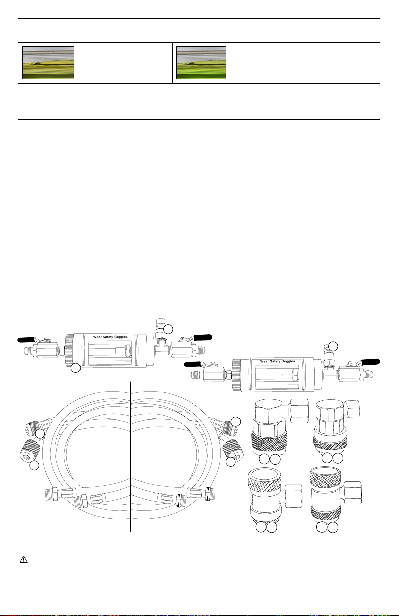
DAS SCHAUGLAS VON KÄLTEMITTEL FREIMACHEN
1. Um das Kältemittel zurück in die Klimaanlage zu bringen, schalten Sie zuerst die Klimaanlage und das Fahr-zeug ab.
2. Schließen Sie die Hochdruck-Kopplung, durch Drehen des Knopfes gegen den Uhrzeigersinn (nur bei manuellen
Kopplungen). Entfernen Sie die rote Kopplung vom der Hochdruck-Anschluss des Fahr-zeugs.
3. Schalten Sie das Fahrzeug und die Klimaanlage ein.
4. Öffnen sie den roten Hochdruck-Kugelhahn am Schauglas.
5. ÖFFNEN SIE LANGSAM DEN BLAUEN NIEDERDRUCK-KUGELHAHN AM SCHAUGLAS.
6. Warten Sie 1 Minute lang, nachdem das flüssige Kältemittel aus dem Schauglas entfernt wurde. Dadurch kann
Kältemittel im blauen Schlauch in die Klimaanlage gelangen.
7. Schließen Sie die Niederdruck-Kopplung durch Drehen des Knopfes gegen den Uhrzeigersinn (nur bei manuellen
Kopplungen). Entfernen Sie die blaue Kopplung vom Niederdruck-Anschluss.
8. Schalten Sie die Klimaanlage und das Fahrzeug ab.
UNTER DEN MÖGLICHEN VERUNREINIGUNGEN, DIE IM PRÜFGLAS GESEHEN WERDEN KÖNNEN, SIND:
VERKOHLTE ÖLPARTIKEL Wenn Öl hohen Temperaturen ausgesetzt ist
GUMMIPARTIKEL Aggressive Säuren dringen in Gummiteile ein
FEUCHTIGKEIT Leckagen, fehlerhaftes oder unzureichendes Vakuum oder Additive von fal-scher/minderw-
ertiger Qualität
SILBERMETALL/-SPÄNE Festfressen des Kompressors oder Abrieb von Metallteilen
AGGRESSIVE SÄUREN Chemische Reaktion zwischen Feuchtigkeit und Kältemittel / Öl oder fehlerhafte Öl-gemische
VERSCHIEDENE PARTIKEL Verschmutzte Stoffe, erzeugt aus der Verwendung minderwertiger oder falscher Addi-tive,
wie z.B. Abdichtungsmittel für Leckagen, UV-Färbemittel oder Ölgemisch-Verbundstoffen
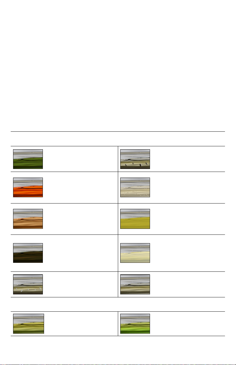
INAKZEPTABLE BEDINGUNGEN
Sofern im Prüfglas zu sehen, sind diese Bedingungen ein Hinweis auf schwerwiegende Anlagen-/Komponentenprobleme
DUNKELGRÜN
Übermäßiges UV-Färbemittel
in der An-lage
GUMMI/KUNSTSTOFF-ZUSAMMENSETZUNGEN
Alte Dichtungen, starke Additive, die mit Dichtun-
gen und Schläuchen rea-gieren, Sammler/Trock-
ner-Ausfall oder zu großer Trocknerverschleiß
ROT / ORANGE
Übermäßige rote Leckage-Na-
chverfolgungsfarbe in der
Anla-ge
BLASEN/PERLEN
Feuchtigkeit in der Anlage; Kontami-nation,
verursacht durch Additive von unzureichender
Qualität; während vorherigen Diensten
gezogenes, feh-lerhaftes Vakuum
HELLBRAUN
Anlage oder Kompressor
übermä-ßiger Überhitzung
ausgesetzt
GELARTIGE, KRISTALLISIERTE STRUKTUR
Abdichtmittel für Leckagen von unzu-reichender
Qualität, die mit Kältemit-tel/Öl oder UV-Färbe-
mittel reagieren; vor Leckage-Stopp-Anwendun-
gen kein/fehlerhaftes Vakuum gezogen
DUNKELBRAUN ODER
SCHWARZ
Anlage oder Kompressor
übermä-ßiger Überhitzung
ausgesetzt
KREMIGE/DIFFUSE STRUKTUR
Aggressive Spülmittelreste, die mit Aluminium-
und Teflonbeschichtung an den Kompressorteilen
reagieren, fehlerhafte Spülung und fehlerhaf-tes
Vakuum nach der Spülung ge-zogen
METALLSPÄNE/-PARTIKEL
Festfressen des Kompressors,
verursacht durch Ölmangel
oder fehlerhafte Schmierung
UNAUSGEGLICHENES FLÜSSIGKEI-TENGEMISCH
Anwendung universeller/falscher Öle; unaus-
geglichenes, uneinheitliches Ge-misch aus
verschiedenen Ölen

7www.mastercool.com
AKZEPTABLE BEDINGUNGEN
Sofern im Prüfglas zu sehen, sind diese Bedingungen ein Hinweis, dass keine Probleme vorliegen
AKZEPTABLE BEDINGUNGEN
Reines Gemisch aus Kälte-
und Schmiermittel
AKZEPTABLE BEDINGUNGEN
Geeignetes Gemisch aus Kältemittel, Schmier-
mittel und UV-Färbemittel
TEILELISTE
Artikel-Nr. Teile-Nr. Beschreibung
1. 53375 Schauglas f. Sichtprüfung Kältemittel-Öl
2. 82274 Niederdruck-Nachrüst-Adapter, 1/4” (7/16”-20) x 13 mm
3. 53376-601 60” Blauer R134a Füllschlauch
4. 53376-603 60” Roter R134a Füllschlauch
5. 66234 R134a Hochdruck-Schnellkopplung
6. 66334 R134a Niederdruck-Schnellkopplung
7. 84274 1/4 fl-f x 17 mm-m R1234yf Adapter mit Ventileinsatz
8. 53376-601YF 60” Blauer R1234yf Füllschlauch
9. 53376-603YF 60” Roter R1234yf Füllschlauch
10. 67434 R1234yf Hochdruck-Schnellkopplung
11. 67534 R1234yf Niederdruck-Schnellkopplung
12. 82834 R134a Manuelle Hochdruck-Kopplung
13. 82934 R134a Manuelle Niederdruck-Kopplung
14. 83834 R1234yf Manuelle Hochdruck-Kopplung mit verlängerter Trennhülse
15. 83934 R1234yf Manuelle Niederdruck-Kopplung mit verlängerter Trennhülse
1
7
10 11
56
3
4
14 15
12 13
9
8
WARNUNG: Durch dieses Produkt können Sie Chemikalien, einschließlich Diethylhexylphthalat, Blei und Blei-verbind-
ungen ausgesetzt sein, welche dem Bundesstaat Kalifornien als krebserregend und Geburtsschäden sowie andere
reproduktive Schäden verursachend bekannt sind. Um weitere Informationen zu erhalten, gehen
Sie zu www.P65Warnings.ca.gov
2

8www.mastercool.com
AVERTISSEMENT
• PORTEZ DES LUNETTES DE PROTECTION !
• ÉVITEZ TOUT CONTACT AVEC LE RÉFRIGÉRANT
PRÉPARER LE VOYANT D’INSPECTION
Utilisation du vide d’une machine à recycler
1. Raccorder les tuyaux rouge et bleu fournis aux extrémités correspondantes du voyant.
2. Raccorder les coupleurs rouge et bleu aux extrémités correspondantes du tuyau. Fermer chaque coupleur en
tournant le bouton dans le sens inverse des aiguilles d’une montre (coupleurs manuels uniquement.) Raccorder
le tuyau bleu du côté bas et le coupleur de votre machine RRR au raccord du côté bas sur le côté bleu du voyant
d’inspection.
3. Ouvrir les deux robinets à boisseau sphérique de chaque côté du voyant.
4. Faire le vide pendant 3 minutes depuis le panneau de commande de votre machine RRR. Cela permettra d’éliminer
toute atmosphère du voyant pour permettre un test précis.
5. Débrancher le coupleur du côté bas de la machine RRR du voyant lorsque le temps d’exécution du vide est terminé.
6. Passer à la section d’utilisation du voyant.
Utilisation du vide d’une pompe à vide
1. Fermer les deux robinets à boisseau sphérique. Raccordez le tuyau rouge fourni au côté rouge du voyant. Fixer le
coupleur du côté haut au tuyau et fermer le coupleur en tournant le bouton dans le sens inverse des aiguilles d’une
montre (coupleurs manuels uniquement)
2. Raccorder le coupleur du côté bas au tuyau bleu et fermer le coupleur en tournant le bouton dans le sens inverse des
aiguilles d’une montre (coupleurs manuels uniquement)
3. Raccorder le coupleur du côté bas à l’orifice de service du voyant . Ouvrir le coupleur en tournant le bouton dans le
sens des aiguilles d’une montre (coupleurs manuels uniquement).
4. Raccorder l’autre extrémité du tuyau bleu à votre pompe à vide.
5. Ouvrir le robinet à boisseau sphérique rouge du côté haut, laisser le robinet à boisseau sphérique bleu du côté bas fermé.
6. Faire fonctionner votre pompe à vide pendant 3 minutes. Cela permettra d’éliminer toute atmosphère du voyant pour
permettre un test précis.
7. Débrancher le tuyau bleu de la pompe à vide lorsque le temps de vide est terminé. Fermer le coupleur du bas en
tournant le bouton dans le sens inverse des aiguilles d’une montre (coupleurs manuels uniquement.) Débrancher
le coupleur bleu du voyant. Les raccords du tuyau bleu et du coupleur sont tous deux dotés de dispositifs d’arrêt
automatique qui maintiennent le vide créé dans le voyant d’inspection et les tuyaux.
8. Raccorder le tuyau bleu au côté bleu du voyant..
UTILISATION DU VOYANT D’INSPECTION
1. Fermer les deux robinets à boisseau sphérique sur le voyant.
2. Brancher le coupleur rouge sur le côté supérieur du système de climatisation. Ouvrir le coupleur en tournant le
bouton dans le sens des aiguilles d’une montre (coupleurs manuels uniquement).
3. Brancher le coupleur bleu sur le côté inférieur du système de climatisation. Ouvrir le coupleur en tournant le bouton
dans le sens des aiguilles d’une montre (coupleurs manuels uniquement).
4. Démarrer le véhicule puis mettre le système de climatisation en marche.
5. Maintenir le voyant en position verticale avec le tuyau rouge vers le bas.
6. Ouvrir LENTEMENT le robinet à boisseau sphérique du côté rouge.
7. Lorsque le voyant d’inspection est rempli avec ¼ de réfrigérant liquide, fermer le robinet à boisseau sphérique latéral
rouge (s’assurer que le robinet à boisseau sphérique latéral bleue est également fermé).
8. Laisser le réfrigérant se stabiliser.
9. Vérifier la couleur du réfrigérant à l’aide du tableau ci-dessous. Vérifier s’il y a des débris dans le réfrigérant..
NETTOYAGE DU VOYANT DU RÉFRIGÉRANT
1. Pour remettre le réfrigérant dans le système de climatisation, arrêter tout d’abord le système de climatisation et le
Français

9www.mastercool.com
véhicule.
2. Fermer le coupleur du haut en tournant le bouton dans le sens inverse des aiguilles d’une montre (coupleurs
manuels uniquement.) Enlever le coupleur rouge du côté haut du véhicule.
3. Mettre le véhicule et le système de climatisation en marche.
4. Ouvrir le robinet à boisseau sphérique rouge du côté haut sur le voyant d’inspection.
5. OUVREZ LENTEMENT LE ROBINET À BOISSEAU SPHÉRIQUE BLEU DU CÔTÉ BAS DU VOYANT.
6. Attendre 1 minute après avoir retiré le réfrigérant liquide du voyant d’inspection. Ceci permet au réfrigérant présent
dans le tuyau bleu de retourner dans le système de climatisation.
7. Fermer le coupleur du bas en tournant le bouton dans le sens inverse des aiguilles d’une montre (coupleurs manuels
uniquement.) Retirer le coupleur bleu du côté bas.
8. Arrêter le système de climatisation et le véhicule.
LES CONTAMINANTS QUI PEUVENT ÊTRE VUS DANS LE VOYANT D’INSPECTION COMPRENNENT:
PARTICULES D’HUILE CARBONISÉE Lorsque l’huile est exposée à des températures élevées
PARTICULES DE CAOUTCHOUC Acides agressifs pénétrant dans les pièces en caoutchouc
HUMIDITÉ Fuites, vide incorrect ou insuffisant ou additifs de mauvaise qualité ou inappropriés
ARGENT MÉTAL/COPEAUX Grippage du compresseur ou abrasion des pièces métalliques
ACIDES AGRESSIFS Réaction chimique entre l’humidité et le réfrigérant/l’huile ou mélanges d’huile
incorrects
AUTRES PARTICULES Composés souillés créés par l’utilisation d’additifs de mauvaise qualité ou inappro-
priés tels que des agents anti-fuite, des colorants UV ou des mélanges d’huiles
CONDITIONS INACCEPTABLES
Ces conditions sont le signe de graves problèmes du système/composant lorsqu’elles sont observées dans le voyant
VERT FONCÉ
Excès de colorant UV dans le
système
COMPOSÉS DE CAOUTCHOUC/PLASTIQUE
Joints vieillis, additifs forts réagissant avec les
joints et les tuyaux, défaillance du sécheur du
récepteur ou usure trop importante du sécheur
ROUGE/ORANGE
Présence excessive de colorant
rouge de traçage des fuites
dans le système
BULLES/PERLES
Humidité dans le système, contamination
causée par des additifs de qualité insuffisante,
vide tiré incorrect lors des services précédents
MARRON CLAIR
Système ou compresseur
soumis à une surchauffe
TEXTURE GELÉE, CRISTALLISÉE
Qualité insuffisante des agents anti-fuite
réagissant avec le réfrigérant/l’huile ou le
colorant UV, vide tiré absent/incorrect avant les
applications anti-fuite
MARRON FONCÉ OU NOIR
Système ou compresseur
soumis à une surchauffe
excessive
TEXTURE CRÈME/NON CLAIRE
Résidus d’agents de rinçage agressifs réag-
issant avec l’aluminium et le revêtement de
téflon sur les pièces du compresseur, rinçage
incorrect et vide tiré après le rinçage
COPEAUX/PARTICULES DE
MÉTAL
Grippage du compresseur dû
à un manque d’huile ou à une
mauvaise lubrification
MÉLANGE DE LIQUIDES NON-ÉQUILIBRÉ
Application d’huiles universelles/incorrectes,
mélange non-équilibré et non-homogène de
diverses huiles
CONDITIONS ACCEPTABLES
Ces conditions indiquent qu’il n’y a pas de problème lorsqu’elles sont observées dans le voyant d’inspection
ÉTAT ACCEPTABLE
Mélange pur de réfrigérant et
de lubrifiant
ÉTAT ACCEPTABLE
Mélange approprié de réfrigérant, de lubrifiant
et de colorant UV

10 www.mastercool.com
LISTE DES PIÈCES
Réf. # Pièce # Description
1. 53375 Voyant d’inspection de l'huile réfrigérante
2. 82274 Côté inférieur, adaptateur de rétrofit 1/4" (7/16"-20) x 13 mm
3. 53376-601 Tuyau de chargement 60" bleu R134a
4. 53376-603 Tuyau de chargement 60" rouge R134a
5. 66234 Coupleur rapide côté haut R134a
6. 66334 Coupleur rapide côté bas R134a
7. 84274 Adaptateur R1234yf 1/4 fl-f x 17 mm-m avec noyau de vanne
8. 53376-601YF Tuyau de chargement 60" bleu R1234yf
9. 53376-603YF Tuyau de chargement 60" rouge R1234yf
10. 67434 Coupleur rapide côté haut R1234yf
11. 67534 Coupleur rapide côté bas R1234yf
12. 82834 Coupleur manuel côté haut R134a
13. 82934 Coupleur manuel côté bas R134a
14. 83834 Coupleur manuel côté haut R1234yf avec manchon de déconnexion prolongé
15. 83934 Coupleur manuel côté bas R1234yf avec manchon de déconnexion prolongé
1
7
10 11
56
3
4
14 15
12 13
9
8
AVERTISSEMENT : ce produit peut vous exposer à des produits chimiques, notamment le phtalate de di(2-éthylhex-
yle), le plomb et les composés du plomb, dont l’État de Californie sait qu’ils provoquent des cancers et des anomalies
congénitales ou d’autres atteintes à la reproduction. Pour plus d’informations, voir le site www.P65Warnings.ca.gov
2

11www.mastercool.com
ADVERTENCIA
• ¡¡USE GUANTES DE PROTECCION!!
• EVITAR CONTACTO CON EL REFRIGERANTE
PREPARAR LA CAPSULA DE VIDRIO PARA LA INSPECCION VISUAL
Al usar el vacío de una máquina de reciclaje
1. Conecte las mangueras roja y azul suministradas al extremo correspondiente de la Cápsula de Vidrio.
2. Conecte los acoples rojo y azul al extremo correspondiente de la manguera. Cierre cada acople girando la perilla en
sentido contrario a las agujas del reloj (solo acoples manuales). Conecte la manguera y acople azul del lado de baja
de su equipo de reciclaje (RRR) con el conector del lado azul de la Cápsula de Vidrio.
3. Abra ambas válvulas de bola a cada lado de la Cápsula de Vidrio.
4. Ejecute un vacío de 3 minutos desde el panel de control de su máquina de reciclaje (RRR). Esto eliminará cualquier
atmósfera dentro de la Cápsula de Vidro, lo cual permitirá hacer una prueba precisa.
5. Una vez se cumpla el tiempo de vacío, desconecte el acople del lado de baja de la máquina de reciclaje (RRR), de la
Cápsula de Vidrio.
6. Vaya a la Sección Uso de la Cápsula de Vidrio
Al usar el vacío de una bomba de vacío
1. Cierre ambas válvulas de bola. Conecte la manguera roja suministrada al lado rojo de la Cápsula de Vidrio. Fije el
acople del lado de alta a la manguera y cierre el acople girando la perilla en sentido contrario a las agujas del reloj
(solo acoples manuales).
2. Conecte el acople del lado de baja de la manguera azul y cierre el acople girando la perilla en sentido contrario a las
agujas del reloj (solo acoples manuales.)
3. Conecte el acople del lado de baja (azul) al puerto de servicio de la Capsula de Vidrio. Abra el acople girando la perilla
en el sentido de las agujas del reloj (sólo acoples manuales.)
4. Conecte el otro extremo de la manguera azul a la bomba de vacío.
5. Abra la válvula de bola del lado de alta (rojo) y deje la válvula de bola del lado de baja (azul) cerrada.
6. Ejecute (con la bomba de vacío) un vacío durante 3 minutos. Esto eliminará cualquier atmósfera de la Cápsula de
Vidrio para permitir una prueba precisa.
7. Desconecte la manguera azul de la bomba de vacío cuando finalice el tiempo de vacío. Cierre el acople del lado
de baja girando la perilla en sentido contrario a las agujas del reloj (solo acoples manuales.) Desconecte el acople
azul de la Cápsula de Vidrio. Los conectores de la manguera azul y el acople, ambos tienen cierre automático que
mantendrá el vacío creado en la Cápsula de Vidrio y mangueras.
8. Conecte la manguera azul al lado azul de la Cápsula de Vidrio.
USO DE LA CAPSULA DE VIDRIO
1. Cierre ambas válvulas en la Capsula de Vidrio.
2. Conecte el acople rojo al puerto de servicio de alta del sistema de A/C. Abra el acople girando la perilla en el sentido
de las agujas del reloj (acoples manuales solamente.)
3. Conecte el acople azul al puerto de servicio de baja del sistema de A/C. Abra el acople girando la perilla en el sentido
de las agujas del reloj (solo acoples manuales.)
4. Encienda el vehículo y encienda el sistema de A/C.
5. Sujete y mantenga la Cápsula de Vidrio en posición vertical con la manguera roja hacia abajo.
6. Abra lentamente la válvula de alta (roja).
7. Cuando ¼ de la Cápsula de Vidrio este llena de refrigerante líquido, cierre la válvula de alta (roja). Asegúrese de que
la válvula de baja (azul) permanezca cerrada.
8. Deje que el refrigerante se estabilice.
9. Compruebe el color del refrigerante utilizando la tabla que se muestra más abajo. Compruebe si hay residuos/
impurezas en el refrigerante.
Español

12 www.mastercool.com
RETORNO DEL REFRIGERANTE DE LA CAPSULA DE VIDRIO AL SISTEMA A/C
1. Para volver a colocar el refrigerante en el sistema de A/C del vehículo, apague primero el sistema de A/C y también
el motor del vehículo.
2. Cierre el acople del lado de alta girando la perilla en sentido contrario a las agujas del reloj (solo acoples manuales.)
Retire el acople rojo del puerto de servicio de alta del vehículo.
3. Encienda el vehículo y el sistema de A/C de este.
4. Abra la válvula del lado de alta (rojo) de la Cápsula de Vidrio.
5. ABRA LENTAMENTE LA VÁLVULA DEL LADO DE BAJA (AZUL) DE LA CAPSULA DE VIDRIO.
6. Espere por lo menos 1 minuto después de que el refrigerante líquido se haya removido de la Cápsula de Vidrio. Esto
permitirá que cualquier residuo de refrigerante que haya quedado en la manguera azul, vuelva al sistema de A/C del
vehículo.
7. Cierre el acople del lado de baja girando la perilla en sentido contrario a las agujas del reloj (solo acoples manuales).
Retire el acople azul del puerto de servicio de baja.
8. Apague el sistema de A/C y el motor del vehículo.
POSIBLES CONTAMINANTES QUE SE PUEDEN VISUALIZAR E INSPECCIONAR EN LA CAPSULA DE VIDRIO:
PARTICULAS DE ACEITE CARBONIZADO Cuando el aceite está expuesto a altas temperaturas
PARTICULAS DE GOMA (CAUCHO) Ácidos agresivos que penetran piezas de goma
HUMEDAD/IMPUREZAS Debido a fugas, vacío incorrecto o insuficiente, aditivos incorrectos y/o de baja
calidad
PARTICULAS/ASTILLAS METALICAS Del compresor, desgaste de piezas
ACIDOS AGRESIVOS Reacción química entre humedad y refrigerante/aceite o mezclas de aceite
incorrectas
OTRAS VARIAS PARTÍCULAS Creadas a partir del uso de aditivos, agentes para detener fugas, tinte UV
incorrectos y/o de mala calidad, compuestos de mezcla de aceite
CONDICIONES INACEPTABLES
Estas condiciones cuando se ven e inspeccionan en la Cápsula de Vidrio, son una indicación de problemas graves del
sistema/componentes.
VERDE OSCURO
Excesivo tinte UV en el sistema.
COMPUESTOS DE CAUCHO/PLÁSTICO
Sellos envejecidos, aditivos fuertes que
reaccionan con sellos y mangueras, falla
del deshumidificador receptor o demasiado
desgaste del deshumidificador.
ROJO/NARANJA
Excesivo tinte (trazador) rojo UV
de rastreo de fugas en el sistema.
BURBUJAS/PERLAS
Humedad en el sistema, contaminación debido
a aditivos de baja calidad, vacío incorrecto
realizado durante servicios anteriores.
MARRÓN CLARO
Sistema o compresor sometido a
temperaturas excesivamente
altas.
TEXTURA CRISTALIZADA, GELATINOSO
Agentes para detener fugas de mala calidad
que reaccionan con refrigerante/aceite o tinte
(trazador) UV, no/vacío incorrecto realizado
antes de la aplicación para detener las fugas.
MARRÓN OSCURO O NEGRO
Sistema o compresor sometido a
temperaturas extremadamente
altas.
CREMA/TEXTURA NO CLARA
Residuos agresivos del agente de lavado que
reaccionan con aluminio y el recubrimiento
de teflón en las partes del compresor, lavado
incorrecto y mal vacío realizado después del
lavado.
PARTÍCULAS/ASTILLAS DE METAL
Falla o traba del compresor
causada por la falta de aceite y/o
lubricación incorrecta.
MEZCLA DE LÍQUIDOS DESEQUILIBRADO
Aplicación de aceites universales-genéricos/
incorrectos, mezcla desequilibrada y no
homogénea de varios aceites.

13www.mastercool.com
CONDICIONES ACEPTABLES
Si se ven las condiciones que se muestran más abajo, es un buen indicativo de que no hay problemas.
CONDICIÓN ACEPTABLE
Mezcla pura y adecuada de
refrigerante y lubricante.
CONDICIONES ACEPTABLES
Mezcla pura y adecuada de refrigerante,
lubricante y el tinte (trazador) UV.
LISTA DE PIEZAS
Ítem Modelo Descripción
1. 53375 Capsula de Vidrio de Inspección para Visual del Aceite Refrigerante
2. 82274 Lado de baja, 1/4” (7/16”-20) x 13 mm, retro adaptador
3. 53376-601 Manguera Azul de carga, 60”, R134a
4. 53376-603 Manguera Roja de carga, 60”, R134a
5. 66234 Acople rápido de alta, R-134a
6. 66334 Acople rápido de baja, R-134a
7. 84274 1/4 fl-f x 17 mm-m R1234yf Adaptador con válvula
8. 53376-601YF Manguera azul de carga, 60", R1234yf
9. 53376-603YF Manguera roja de carga, 60", R1234yf
10. 67434 Acople rápido de alta, R1234yf
11. 67534 Acople rápido de baja, R1234yf
12. 82834 Acople Manual de alta, R134a
13. 82934 Acople Manual de baja, R134a
14. 83834 Acople Manual de alta, R1234yf, con una extensión de manguera para desconexión
15. 83934 Acople Manual de baja, R1234yf, con una extensión de manguera para desconexión
1
7
10 11
56
3
4
14 15
12 13
9
8
ADVERTENCIA: Este producto puede exponerlo a productos químicos como Di (2-etilhexil) ftalato, plomo y
compuestos de plomo, que son conocidos por el Estado de California como causantes de cáncer y defectos de
nacimiento u otros daños reproductivos. Para más información ir a www.P65Warnings.ca.gov
2

14 www.mastercool.com
ATTENZIONE
• INDOSSARE OCCHIALI PROTETTIVI!
• EVITARE IL CONTATTO CON IL REFRIGERANTE
PREPARAZIONE DELLO STRUMENTO
Se si utilizza vuoto prodotto da una macchina per il riciclo
1. Collegare il tubo rosso e quello blu in dotazione alla corri-spondente estremità dello strumento d’ispezione.
2. Collegare alla corrispondente estremità di ciascun tubo uno degli attacchi (rosso e blu) in dotazione. Chiudere
ciascun attacco girando la manopola in senso antiorario (vale per gli attacchi manuali). Collegare il tubo e l’attacco
blu lato di bassa in uscita dalla macchina RRR al raccordo lato-bassa sul lato blu dello strumento d’ispezione.
3. Aprire la valvola a sfera su ciascun lato dello strumento.
4. Dal pannello di controllo della macchina RRR, pompare vuoto per 3 minuti. In questo modo l’intera atmosfera dello
strumento d’ispezione verrà estratta in modo da consentire un test accurato.
5. Dopo aver fatto il vuoto, scollegare dallo strumento l’attacco della macchina RRR lato di bassa.
6. Andare al paragrafo “Uso dello strumento d’ispezione”.
Se si utilizza vuoto prodotto da una pompa
1. Chiudere entrambe le valvole a sfera. Collegare il tubo rosso in dotazione al lato rosso dello strumento d’ispezio-ne.
Collegare l’attacco lato alta pressione al tubo e chiudere l’attacco girando la manopola in senso antiorario (vale per
gli attacchi manuali).
2. Collegare l’attacco lato-bassa al tubo blu e chiudere l’attac-co girando la manopola in senso antiorario (vale per gli
at-tacchi manuali).
3. Collegare l’attacco lato di bassa alla bocchetta di servizio dello strumento. Aprire l’attacco girando la manopola in
senso orario (vale per gli attacchi manuali).
4. Collegare l’altro capo del tubo blu alla pompa per vuoto.
5. Aprire la valvola a sfera rossa lato alta pressione e lascia-re chiusa la valvola a sfera blu lato-bassa.
6. Fate funzionare per 3 minuti la pompa per vuoto. In questo modo l’intera atmosfera dello strumento verrà estratta per
consentire un test accurato.
7. Dopo aver fatto il vuoto, scollegare il tubo blu dalla pompa. Chiudere l’attacco lato di bassa girando la manopola
in senso antiorario (vale per gli attacchi manuali). Scollegare l’attacco blu dallo strumento d’ispezione. I raccordi
presenti sul tubo e sull’attacco blu sono entrambi dotati di chiusura automatica che manterrà il vuoto creato nello
strumento e nei tubi.
8. Collegare il tubo blu al lato blu dello strumento d’ispezione.
USO DELLO STRUMENTO D’ISPEZIONE
1. Chiudere entrambe le valvole a sfera dello strumento d’ispezione.
2. Collegare l’attacco rosso al lato-alta dell’impianto AC. Aprire l’attacco girando la manopola in senso orario (vale per
gli attacchi manuali).
3. Collegare l’attacco blu al lato-bassa dell’impianto AC. Aprire l’attacco girando la manopola in senso orario (vale per
gli attacchi manuali).
4. Avviare il veicolo e poi accendere l’impianto AC.
5. Mantenere lo strumento d’ispezione in posizione verticale, con il tubo rosso in basso.
6. Aprire LENTAMENTE la valvola a sfera sul lato rosso.
7. Quando lo strumento d’ispezione è pieno per ¼ di refrigerante liquido, chiudere la valvola a sfera sul lato rosso
(assicurarsi che anche la valvola a sfera sul lato blu sia ancora chiusa).
8. Attendere che il refrigerante si stabilizzi.
9. Controllare il colore del refrigerante utilizzando lo schema fornito più avanti. Verificare che nel refrigerante non siano
presenti residui.
RIMOZIONE DEL REFRIGERANTE DALLO STRUMENTO
1. Per reintrodurre il refrigerante nell’impianto AC, spegnere prima l’impianto e il veicolo.
Italiano

15www.mastercool.com
2. Chiudere l’attacco lato alta pressione girando la manopola in senso antiorario (vale per gli attacchi manuali).
Rimuovere l’attacco rosso dal lato alta pressione del veicolo.
3. Accendere il veicolo e l’impianto AC.
4. Aprire la valvola a sfera rossa lato alta pressione dello strumento.
5. APRIRE LENTAMENTE LA VALVOLA A SFERA BLU SUL LATO DI BASSA PRESSIONE DELLO STRUMENTO D’ISPEZIONE.
6. Attendere 1 minuto dopo la rimozione del liquido refrigerante dallo strumento. In questo modo tutto il refrigerante
presente nel tubo blu verrà immesso nell’impianto AC.
7. Chiudere l’attacco lato-bassa girando la manopola in senso antiorario (vale per gli attacchi manuali). Rimuovere
l’attacco blu dal lato-bassa.
8. Spegnere l’impianto AC e il veicolo..
TRA I CONTAMINANTI CHE POSSONO ESSERE RILEVATI DALLO LO STRUMENTO D’ISPEZIONE
DURANTE L’ISPEZIONE VI SONO:
PARTICELLE DI OLIO
CARBONIZZATO Quando l’olio viene esposto ad alte temperature
PARTICELLE DI GOMMA Acidi aggressivi che penetrano nelle parti in gomma
UMIDITÀ
Perdite, vuoto non corretto o insufficiente oppure additivi inappropriati o di cattiva qualità
ARGENTO METALLO/FRAMMENTI Grippaggio del compressore o abrasione delle parti metalliche
ACIDI AGGRESSIVI Reazione chimica tra umidità e refrigerante/olio o miscele d’olio non corrette
PARTICELLE DI VARIO TIPO Composti contaminati creati a seguito dell’utilizzo di additivi inappro-priati o di catti-
va qualità, quali agenti tura-falle, traccianti fluorescenti o composti di miscele d’olio
CONDIZIONI NON ACCETTABILI
Se rilevate attraverso lo strumento durante l’ispezione, le condizioni di seguito descritte segnalano gravi problemi a
livello di impianto/componenti
VERDE SCURO
Presenza di tracciante UV in eccesso
nell’impianto
COMPOSTI DI GOMMA/PLASTICA
Guarnizioni vecchie, reazione di additivi
aggressivi con guarnizioni e tubi, gua-
sto all’essiccatore del serbatoio o
essic-catore usurato
ROSSO/ARANCIO
Presenza eccessiva di tracciante rosso
per la ricerca di perdite nell’impianto
BOLLE/PERLE
Umidità nell’impianto, contaminazione
causata da additivi di cattiva qualità
o non corretta produzione del vuoto
du-rante precedenti interventi di manu-
tenzione
MARRONE CHIARO
Impianto o compressore sottoposti a
surriscaldamento
CONSISTENZA CRISTALLIZZATA,
GELATINOSA
Reazione di agenti tura-falle di qualità
scadente con refrigerante/olio o trac-ci-
anti UV, produzione del vuoto assen-te
o non corretta prima dell’applicazio-ne
di agenti tura-falle
MARRONE SCURO O NERO
Impianto o compressore sottoposti a
surriscaldamento eccessivo
CONSISTENZA PASTOSA/OPACA
Reazione di residui di agenti di
la-vaggio aggressivi con il rivestimento
di alluminio e teflon delle parti del
compressore, lavaggio e produzione del
vuoto dopo il lavaggio non cor-retti
FRAMMENTI/PARTICELLE DI MET-
ALLO
Grippaggio del compressore cau-sato
dalla mancanza di olio o da una lubrifi-
cazione non corretta
MISCELA DI LIQUIDI SBILANCIATA
Utilizzo di oli universali/non corretti,
mi-scela non uniforme e non omogenea
di oli diversi

16 www.mastercool.com
CONDIZIONI ACCETTABILI
Le condizioni di seguito descritte, se rilevate attraverso lo strumento durante l’ispezione, indicano l’assenza di problemi
CONDIZIONE ACCETTABILE
Pura miscela di refrigerante e lubrif-
icante
CONDIZIONE ACCETTABILE
Appropriata miscela di refrigerante,
lubri-ficante e tracciante fluorescente
LISTA DELLE PARTI
Elemento n. N. catalogo Descrizione
1. 53375 Unità di ispezione visiva per olio refrigerante
2. 82274 Lato bassa pressione, adattatore retrofit 1/4” (7/16”-20) x 13 mm
3. 53376-601 Tubo di carico per R134a blu 60”
4. 53376-603 Tubo di carico per R134a rosso 60”
5. 66234 Attacco rapido per R134a lato-alta
6. 66334 Attacco rapido per R134a lato-bassa
7. 84274 Adattatore per R1234yf 1/4 fl-f x 17 mm-m con nucleo della valvola
8. 53376-601YF Tubo di carico per R1234yf blu 60”
9. 53376-603YF Tubo di carico per R1234yf rosso 60”
10. 67434 Attacco rapido per R1234yf lato-alta pressione
11. 67534 Attacco rapido per R1234yf lato-bassa pressione
12. 82834 Attacco manuale per R134a lato-alta
13. 82934 Attacco manuale per R134a lato-bassa
14. 83834 Attacco manuale per R1234yf lato-alta con manicotto di disconnessione prolungato
15. 83934 Attacco manuale per R1234yf lato-bassa con manicotto di disconnessione
prolungato
1
7
10 11
56
3
4
14 15
12 13
9
8
ATTENZIONE: questo prodotto può esporvi a sostanze chimiche tra cui il di(2-etilesil)ftalato, piombo e composti del
piombo, che nello Stato della California sono riconosciuti come causa di cancro e di difetti alla nascita, o di altri danni
riproduttivi. Per altre informazioni, visitare www.P65Warnings.ca.gov
2

17www.mastercool.com
WAARSCHUWING
• DRAAG EEN VEILIGHEIDSBRIL!!
• VERMIJD CONTACT MET HET KOELMIDDEL
HET KIJKGLAS VOORBEREIDEN
Bij gebruik van vacuüm uit een recycleermachine
1. Verbind zowel de meegeleverde rode als blauwe slangen aan het overeenkomstige uiteinde van het kijkglas.
2. Verbind zowel de rode als de blauwe koppeling aan het overeenkomstige uiteinde van de slang. Sluit elke koppeling
door de knop linksom te draaien (enkel handmatige koppelingen.) Verbind de blauwe slang van de lagedrukzijde en
de koppeling van uw RRR machine aan de fitting van de lagedrukzijde op de blauwe zijde van het kijkglas.
3. Open de kogelkranen aan elke zijde van het kijkglas.
4. Vacuümeer gedurende 3 minuten vanuit het controlepaneel op uw RRR machine. Dit haalt alle lucht uit het kijkglas
om een nauwkeurige test mogelijk te maken.
5. Maak de koppeling van RRR machine aan de lagedrukzijde los van het kijkglas wanneer de vacuümeertijd voorbij is.
6. Ga naar de rubriek over het gebruik van het kijkglas.
Bij het gebruik van vacuüm vanuit een vacuümpomp
1. Sluit beide kogelkranen. Verbind de meegeleverde rode slang aan de rode zijde van het kijkglas. Bevestig de
koppeling van de hogedrukzijde aan de slang en sluit de koppeling door de knop linksom te draaien (enkel
handmatige koppelingen.)
2. Verbind de koppeling van de lagedrukzijde met de blauwe slang en sluit de koppeling door de knop linksom te
draaien (enkel handmatige koppelingen.)
3. Verbind de koppeling van de lagedrukzijde aan de servicepoort op het kijkglas. Open de koppeling door de knop
rechtsom te draaien (enkel handmatige koppelingen.)
4. Verbind het andere uiteinde van de blauwe slang met uw vacuümpomp.
5. Open de rode kogelkraan aan de hogedrukzijde, laat de blauwe kogelkraan aan de lagedrukzijde gesloten.
6. Laat uw vacuümpomp gedurende 3 minuten. Dit haalt alle lucht uit het kijkglas om een nauwkeurige test mogelijk te
maken.
7. Maak de blauwe slang los van de vacuümpomp wanneer de vacuümeertijd voorbij is. Sluit de koppeling van de
lagedrukzijde door de knop linksom te draaien (enkel handmatige koppelingen.) Maak de blauwe koppeling los van
het kijkglas. De fittingen aan de blauwe slang en de koppeling kunnen beide automatisch worden afgesloten. Dit
houdt het gecreëerde vacuüm in het kijkglas en de slangen.
8. Verbind de blauwe slang aan de blauwe zijde van het kijkglas.
HET KIJKGLAS GEBRUIKEN
1. Sluit beide kogelkranen op het kijkglas.
2. Verbind de rode koppeling met de hogedrukzijde van het AC-systeem. Open de koppeling door de knop rechtsom te
draaien (enkel handmatige koppelingen.)
3. Verbind de blauwe koppeling met de lagedrukzijde van het AC-systeem. Open de koppeling door de knop rechtsom
te draaien (enkel handmatige koppelingen.)
4. Start het voertuig en schakel het AC-systeem in.
5. Houd het kijkglas verticaal met de rode slang naar beneden
6. Open de kogelkraan van de rode zijde LANGZAAM.
7. Wanneer het kijkglas een kwart gevuld is met vloeibaar koelmiddel, sluit de kogelkraan van de rode zijde (zorg
ervoor dat de kogelkraan van de blauwe zijde ook nog steeds gesloten is).
8. Laat het koelmiddel stabiliseren.
9. Controleer de kleur van het koelmiddel met behulp van de tabel hieronder. Controleer of er zich stukjes in het
koelmiddel bevinden.
HET KIJKGLAS VRIJMAKEN VAN KOELMIDDEL
1. Om het koelmiddel terug in het AC-systeem te brengen, moet eerst het AC-systeem en het voertuig worden
Nederlands

18 www.mastercool.com
uitgeschakeld.
2. Sluit de koppeling aan de hogedrukzijde door de knop linksom te draaien (enkel handmatige koppelingen.) Verwijder
de rode koppeling van de hogedrukzijde van het voertuig.
3. Schakel het voertuig en het AC-systeem in.
4. Open de rode kogelkraan aan de hogedrukzijde op het kijkglas.
5. OPEN LANGZAAM DE BLAUWE KOGELKRAAN VAN DE LAGEDRUKZIJDE OP HET KIJKGLAS.
6. Wacht 1 minuut nadat het vloeibaar koelmiddel is verwijderd uit het kijkglas. Dit maakt het mogelijk dat koelmiddel
in de blauwe slang in het AC-systeem kan.
7. Sluit de koppeling van de lagedrukzijde door de knop linksom te draaien (enkel handmatige koppelingen.) Verwijder
de blauwe koppeling van de lagedrukzijde.
8. Schakel het AC-systeem en het voertuig uit.
DE MOGELIJKE VERONTREINIGINGEN DIE TE ZIEN KUNNEN ZIJN IN HET KIJKGLAS ZIJN:
GECARBONISEERDE OLIEPARTIKELS Wanneer olie is blootgesteld aan hoge temperaturen
RUBBERPARTIKELS Agressieve zuren die de rubber onderdelen binnendringen
VOCHT Lekken, incorrect of onvoldoende vacuüm of verkeerde/lagekwaliteitsadditieven
METALEN ZILVER/SCHILFERTJES Falen van de compressor of slijtage van de metalen onderdelen
AGRESSIEVE ZUREN Chemische reactie tussen vocht en koelmiddel/olie of incorrecte oliemengsels
VERSCHILLENDE PARTIKELS Vuile bestanddelen door gebruik van lagekwaliteits- of incorrecte additieven
zoals lekstopmiddelen, UV-kleurstof of oliemengsels
ONAANVAARDBARE OMSTANDIGHEDEN
Wanneer deze omstandigheden te zien zijn in het kijkglas, zijn dit een indicatie van ernstige problemen in het systeem/
onderdelen
DONKERGROEN
Overmatig UV-kleurstof in het
systeem
RUBBER/PLASTIC BESTANDDELEN
Oude afdichtingen, sterke additieven die
reageren met afdichtingen en slangen, fout
in filterdroger of te veel drogerslijtage
ROOD/ORANJE
Overmatige rode lektraceerkleurst-
of in het systeem
BUBBEL/PARELS
Vocht in het systeem, verontreiniging
veroorzaakt door additieven van
onvoldoende kwaliteit, incorrect vacuüm
getrokken tijdens de vorige services
LICHTBRUIN
Systeem of compressor bloot-
gesteld aan oververhitting
GEL-ACHTIGE, GEKRISTALLISEERDE
TEXTUUR
Lekstopmiddelen van onvoldoende
kwaliteit die reageren met koelmiddel/olie
of UV-kleurstof, geen/incorrect vacuüm
getrokken voorafgaand aan lekstoptoe-
passingen
DONKERBRUIN OF ZWART
Systeem of compressor
blootgesteld aan overmatige
oververhitting
ROOMKLEURIGE/ONDOORZICHTIGE
TEXTUUR
Agressieve spoelmiddelresten die reageren
met aluminium en tefloncoating op de
onderdelen van de compressor, incorrect
spoelen en vacuüm getrokken na spoelen
METALEN SCHILFERS/PARTIKELS
Falen van de compressor door ver-
ouderde olie of incorrecte smering
ONEVENWICHTIG VLOEISTOFMENGSEL
Toepassing van universele/incorrecte oliën,
onevenwichtig, niet-homogeen mengsel van
verschillende oliën

19www.mastercool.com
AANVAARDBARE OMSTANDIGHEDEN
Wanneer deze omstandigheden te zien zijn in het kijkglas, zijn dit een indicatie dat er geen problemen zijn
AANVAARDBARE OMSTANDIGHEID
Puur mengsel van koelmiddel en
smeermiddel
AANVAARDBARE OMSTANDIGHEID
Gepast mengsel van koelmiddel, smeermid-
del en UV-kleurstof
LIJST VAN ONDERDELEN PARTS LIST
Itemnr. Onderdeelnr. Beschrijving
1. 53375 Kijkglas voor visuele inspectie van koelmiddelolie
2. 82274 Lagedrukzijde, 1/4” (7/16”-20) x 13 mm Retrofitadapter
3. 53376-601 60” Blauwe R134a Vulslang
4. 53376-603 60” Rode Red R134a Vulslang
5. 66234 R134a Snelkoppeling hogedrukzijde
6. 66334 R134a Snelkoppeling lagedrukzijde
7. 84274 1/4 fl-f x 17 mm-m R1234yf Adapter met ventielinzetstuk
8. 53376-601YF 60” Blauwe R1234yf Vulslang
9. 53376-603YF 60” Rode R1234yf Vulslang
10. 67434 R1234yf Snelkoppeling hogedrukzijde
11. 67534 R1234yf Snelkoppeling lagedrukzijde
12. 82834 R134a Handmatige koppeling hogedrukzijde
13. 82934 R134a Handmatige koppeling lagedrukzijde
14. 83834 R1234yf Handmatige koppeling hogedrukzijde met verlengde ontkoppelingsbus
15. 83934 R1234yf Handmatige koppeling lagedrukzijde met verlengde ontkoppelingsbus
1
7
10 11
56
3
4
14 15
12 13
9
8
WAARSCHUWING: Dit product kan u blootstellen aan chemische producten inclusief Di (2-ethylhexyl) ftalaat die gek-
end zijn bij de Staat van Californië om kanker en geboorteafwijkingen of andere reproductieve schade te veroorzaken.
Ga voor meer informatie naar www.P65Warnings.ca.gov
2

20 www.mastercool.com
AVISO
• USAR ÓCULOS !!
• EVITE CONTATO COM REFRIGERANTE
PREPARAÇÃO DA INSPEÇÃO VISUAL
Quando usar o vácuo de uma máquina de reciclagem
1. Conecte as mangueiras vermelha e azul fornecidas à extremidade correspondente do visor.
2. Conecte o engate vermelho e azul à extremidade correspondente da mangueira. Feche cada engate girando o botão
no sentido anti-horário (somente engates manuais.) Conecte a mangueira azul lateral baixa e o engate da sua
máquina RRR ao encaixe lateral abaixo no lado azul do visor.
3. Abra as duas válvulas de esfera em cada lado do visor.
4. Execute um vácuo por 3 minutos no painel de controle da sua máquina RRR. Isso removerá qualquer atmosfera do
visor para permitir um teste preciso.
5. Desconecte o engate da máquina RRR do lado inferior do visor quando o tempo de execução de vácuo estiver
concluído.
6. Vá para o uso da seção de visor.
Quando usar o vácuo de uma bomba de vácuo
1. Feche as duas válvulas de esfera. Conecte a mangueira vermelha fornecida ao lado vermelho do visor. Encaixe o
engate lateral alto na mangueira e feche o engate girando o botão no sentido anti-horário (somente engates manuais).
2. Conecte o engate lateral baixo à mangueira azul e feche o engate girando o botão no sentido anti-horário (somente
engates manuais).
3. Conecte o engate lateral baixo à porta de serviço no visor. Abra o engate girando o botão no sentido horário (somente
engates manuais.)
4. Conecte a outra extremidade da mangueira azul à sua bomba de vácuo.
5. Abra a válvula de esfera lateral alta vermelha, deixe a válvula de esfera lateral de baixa azul fechada.
6. Opere sua bomba de vácuo por 3 minutos. Isso removerá qualquer atmosfera do visor para permitir um teste preciso.
7. Desconecte a mangueira azul da bomba de vácuo quando o tempo de aspiração estiver concluído. Feche o engate
lateral baixo, girando o botão no sentido anti-horário (somente engates manuais.) Desconecte o engate azul do visor.
Os acessórios na mangueira azul e no engate têm desligamentos automáticos, os quais manterão o vácuo criado no
visor e nas mangueiras.
8. Conecte a mangueira azul ao lado azul do visor.
USANDO O PIREX VISUAL
1. Feche as duas válvulas de esfera no visor.
2. Conecte o engate vermelho ao lado alto do sistema AC. Abra o engate girando o botão no sentido horário (somente
engates manuais.)
3. Conecte o engate azul ao lado inferior do sistema AC. Abra o engate girando o botão no sentido horário (somente
engates manuais.)
4. Dê partida no veículo e ligue o sistema AC.
5. Segure o visor na posição vertical com a mangueira vermelha abaixada.
6. Abra LENTAMENTE a válvula de esfera lateral vermelha.
7. Quando o visor estiver cheio de refrigerante líquido, feche a válvula de esfera lateral vermelha (verifique se a válvula
de esfera lateral azul ainda está fechada).
8. Deixe o refrigerante estabilizar.
9. Verifique a cor do refrigerante usando a tabela abaixo. Verifique se há detritos no refrigerante.
LIMPAR O PIREX VISUAL DO REFRIGERANTE
1. Para colocar o refrigerante de volta no sistema AC, primeiro desligue o sistema AC e o veículo.
2. Feche o engate lateral alta, girando o botão no sentido anti-horário (apenas engates manuais.) Remova o engate
vermelho do lado superior do veículo.
Portuguese
This manual suits for next models
3
Table of contents
Languages:
Other Master cool Service Equipment manuals