SyxthSense SYX-CSC-V User manual

SYX661-CSC Commissioning Guide V1.1 10/2020
Page 1 of 17

SYX661-CSC Commissioning Guide V1.1 10/2020
Page 2 of 17
Table of Contents
1. INTRODUCTION.......................................................................................................................................................3
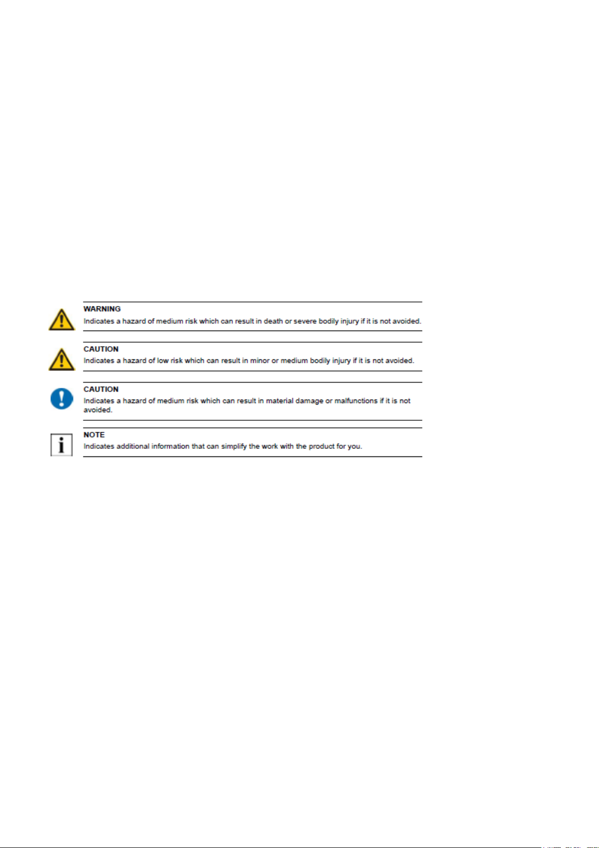
1.1 Important Information Regarding Product Safety..........................................................................................4
1.2 Notes on Disposal...........................................................................................................................................4
1.3 INPUTS ............................................................................................................................................................5
1.5 OUTPUTS.........................................................................................................................................................6
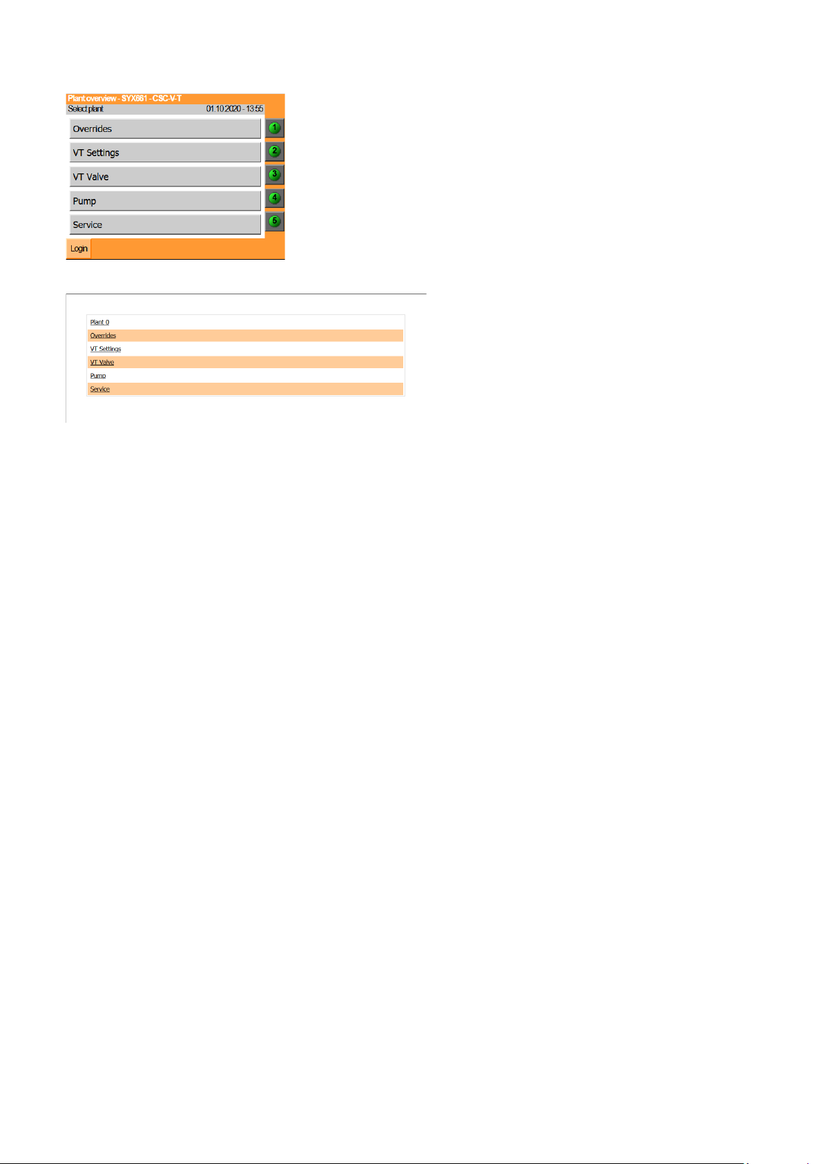
1.6 WEB BROWSER CONNECTION..............................................................................................................................7
2 CONFIGURATION OVERVIEW..................................................................................................................................8
3 Equipment Selection and location..........................................................................................................................9
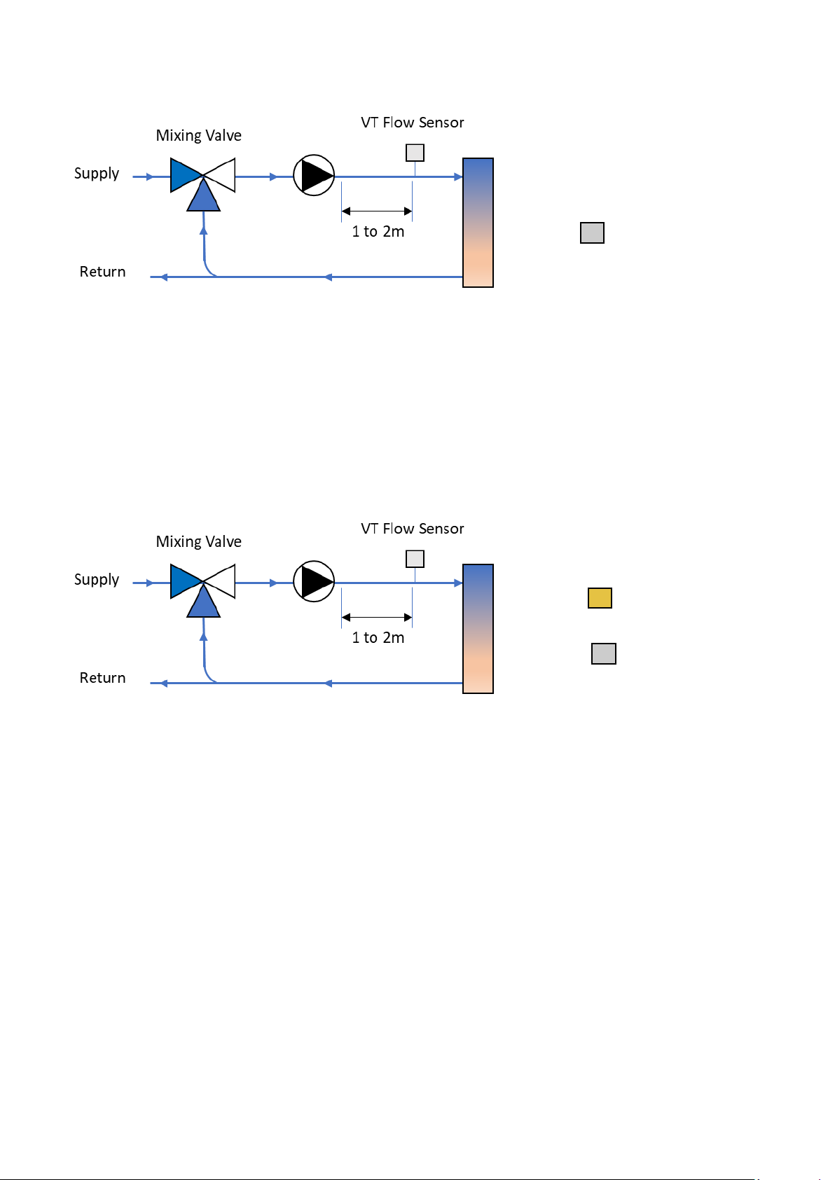
3.1 Heating Application Example (CSC-V) - Valve Control Only .................................................................................9
3.2 Heating Application Example (CSC-V-T)- Pump and Valve Control ......................................................................9
3.2 Access and Controller Configuration....................................................................................................................9
6.1 SYX661-CSC-V-T ............................................................................................................................................11
7. Controller Settings in detail..................................................................................................................................11
7.1 Outside High Limit ........................................................................................................................................11
7.2 Frost Protection (SYX661-CSC-V-T Only) ......................................................................................................11
7.3 Pump Overrun ..............................................................................................................................................11
7.4 Valve Exercise ...............................................................................................................................................12
7.5 Pump Exercise...............................................................................................................................................12
7.6 Heating Time Extension (CSC-V-T)................................................................................................................12
7.7 Summer Winter Time Change and Leap Years .............................................................................................12
7.8 Flow Temperature High Limit.......................................................................................................................12
8. Parameter Summary –CSC-V and CSC-V-T Controllers........................................................................................13
8.1 Connecting with a laptop..............................................................................................................................15
8.2 Passcodes......................................................................................................................................................15
8.3 Factory Defaults............................................................................................................................................15
8.4 Service Level - Sensor Calibration.................................................................................................................15
9. Overrides ..............................................................................................................................................................16
10. Alarms and Management .................................................................................................................................16
10.1 Flow High Limit .............................................................................................................................................16
10.2 Sensor Alarms...............................................................................................................................................16
11. Maintenance and Warranty .............................................................................................................................16
12. FAQ ...................................................................................................................................................................16

SYX661-CSC Commissioning Guide V1.1 10/2020
Page 3 of 17
1. INTRODUCTION
The SYX661 CSC controllers are configured by the installer in the field to provide control of simple Variable
Temperature plant. The flow setpoint is calculated based on the standard VT slope principle to cater for building heat
losses. The VT valve is modulated to control the flow temperature required. If the controller is overridden to Night
mode, open the NSB contact) the flow setpoint is reduced by the night reduction setting. If the controller is overridden
to Boost mode, open the Boost contact) the flow setpoint is increased by 20’C. The temperature can be limited by
flow maximum and flow minimum settings.
Controllers will also provide alarm indication via a dedicated output. This will close should a sensor fail or if the flow
high limit alarm has been triggered. (5’C above Flow Max setting for 30 seconds)
The info button provides direct access to visual indication of all input and output status.
The Malfunction button allows the alarms to be seen and actioned
There is a user button to quickly acknowledge and clear Alarms
The simple user screen is text based using simple language and is backlit for easy use in poor plant room lighting.
The internal web browser allows local site and remote site monitoring/supervision. Users can interrogate relevant
parameters with 3 distinct user levels. Access levels are changed by entering the correct code between: Information
Level (default), Change Level, Set-up level.
Historical records of temperature are taken at regular
intervals and sensor are monitored for their operational
condition. Performance can be assessed and savings increased through better information and analysis. Simple
configuration and simple use are key features of the SYX661-CSC Controllers.

SYX661-CSC Commissioning Guide V1.1 10/2020
Page 4 of 17
1.1 Important Information Regarding Product Safety
Safety Instructions
This document contains information on installing and commissioning the product "SYX66x". Each person who carries
out work on this product must have read and understood this document. If you have any questions that are not
resolved by this document, you can obtain further information from the supplier.
If the product is not used in accordance with this document, the protection provided will be impaired.
Applicable regulations must be observed when installing and using the device. Within the EU, these include
regulations regarding occupational safety and accident prevention as well as those from the
VDE (Association for Electrical, Electronic & Information Technologies). If the device is used in other countries, it is
the responsibility of the system installer or operator to comply with local regulations.
Mounting, installation and commissioning work on the devices may only be carried out by qualified technicians.
Qualified technicians are persons who are familiar with the described product and who can assess given tasks and
identify possible dangers due to technical training, knowledge and experience as well as knowledge of the appropriate
regulations.
1.2Notes on Disposal
For disposal, the product is considered waste from electrical and electronic equipment (electronic waste) and must
not be disposed of as household waste. Special treatment for specific components may be legally binding or
ecologically sensible. The local and currently applicable legislation must be observed.

SYX661-CSC Commissioning Guide V1.1 10/2020
Page 5 of 17
1.3 INPUTS
Temperature sensor inputs and DigitalInputsare available and are to be used
as follows.
The sensor characteristic type to be used is NTC103KA1:
Terminal
Pin
Function
Details
13&15
Pin 1
Outside Air Temperature
Sensor Part:
TEU-NTC10
•
Outside economy
•
Compensation
•
Frost protection
14&15
Pin 2
Compensator Flow Sensor
Sensor Part:
TEAT Immersion
or TEP Strap-On
•
Heating Valve Compensation
Control
16&15
Pin 3
Room Sensor (CSC-V-T)
Sensor Part:
TERP
•
Room Influence
•
Space Frost protection
35+30
Pin 8
Day Extend (CSC-V-T)
•
Close the contact to put the
controller into Day Mode
27&28
Pin 9
Night Reduction
•
Open to put the controller into Night
Setback Mode. This reduces the
calculated flow temperature by the
user set night setback value.
29&30
Pin 10
Boost Mode
•
Open then connection to put the
controller into Boost Mode. This
raises the calculated flow
temperature by 20’C
Special Note: Are the overrides being used?
The Satchwell CSC controller had normally closed contacts for the Night and Boost Modes, if these are not being
used on the above P9 and P10 connections then the above Night terminals need to be linked as do the Boost
Terminals when installing the controller.

SYX661-CSC Commissioning Guide V1.1 10/2020
Page 6 of 17
1.5 OUTPUTS
All the relay outputs are 230Vac 5A rated SPST. The switch feeds can be Volt Free, 230v or 24v and all switched
feeds derived from an external source that the installer must connect as required. The HWS output requires an
auxiliary relay to function (see HWS relay wiring diagram). The outputs are allocatedas
follows:
Terminal
Pin
Function
Details
3&4
Pin 11
VT Valve Open
•
Actuator open signal VFC, 230V or 24v
reversing actuator (supply to be provided)
5&6
Pin 12
VT Valve Close
•
Actuator close signal VFC, 230V or 24v
reversing actuator (supply to be provided)
7&8
Pin 13
Pump
•
VFC Control output either direct to Pump
enable or via a relay/contactor
•
Can also be used to drive a twin pump set via
the PMPCO Auto change over module from
SyxthSense
9&10
Pin 14
Day Mode
•
Closes when the controller is running in Day
Mode to drive other external equipment.
11&12
Pin 15
Alarm Output
•
Closes when a fault is seen with a sensor or
on VT Flow High Limit
•

SYX661-CSC Commissioning Guide V1.1 10/2020
Page 7 of 17
1.6 WEB BROWSER CONNECTION
Customer Interface is possible using a Web Browser, Smart Phone (with SYX661-CSC connected to a network with
Wi-Fi access). Users can quickly:
•
Check current status of control system
•
Change User level
•
Change of settings
•
View historic information
•
Time Schedule and Holiday Planning
•
Configuration of all the controller options
•
Remote overrides and time extensions
•
Observe Live Controller Operation
IP: 192.168.1.99
SM: 255.255.255.0
DG: 192.168.1.1
Users must ensure that their chosen device is configured to be on the same network range to ensure that a
connection can be made. For more information please see the Laptop Fixed IP config video on SyxthSense Video
Resource Library
http://www.syxthsense.com/video_resources

SYX661-CSC Commissioning Guide V1.1 10/2020
Page 8 of 17
2CONFIGURATION OVERVIEW
The SYX661-CSC controller is configured by the installer to provide control of simple Variable Temperature circuits.
On start-up, the settings have been pre-set to
give sensible values suitable for a Radiator VT Heating System, the
settings can be adapted to suit other heating systems such as underfloor heating, radiant panels, and fan convectors
with the ability to compensate above a defined minimum flow setting.

SYX661-CSC Commissioning Guide V1.1 10/2020
Page 9 of 17
3Equipment Selection and location
3.1 Heating Application Example (CSC-V) - Valve Control Only
3.2 Heating Application Example (CSC-V-T)- Pump and Valve Control
3.2 Access and Controller Configuration
To Set-up the controller, the user must be logged into the SYX661-CSC at level 2.
To access the Logon Screen on the controller please Press and Hold the ESC button for 5 Seconds.
Select User 2
The passcode for Set-up level is 0112
Turn and Press the Wheel to select the above code
Once you have 0112 on the Controller press the Select Button to enter it
To access the Logon Screen using the browser or the TPC Touchscreen select the Logon Button in the bottom corner
and follow the same instructions as above but using the keys on the screen. Press enter on the screen to enter the
value.
Once at this User Level the Set-Up Menu options are available to tune the controller to the application you have.
Each menu shown on the controller interface (shown below) has application Set-Up features inside.
The controller offers a menu structure and the navigation can be made using the controller interface or the web
Room Sensor (Optional)
Outside Sensor (North Wall)

SYX661-CSC Commissioning Guide V1.1 10/2020
Page 10 of 17
browser. The controller offers two different browser options as shown below with and without /mo/ after the IP address
of the controller and either can be used:
Above: example 192.168.1.99/mo/
Above: example using basic browser on 192.168.1.99
Once logged into the controller at Level 2 you can configure the controller.

SYX661-CSC Commissioning Guide V1.1 10/2020
Page 11 of 17
6.1 SYX661-CSC-V-T
The SYX661-CSC-V-T has a key configuration option. This selects how the time schedule controls the heating.
Access the controller at user level 2, Select Overrides, Switch then navigate to the Times Clock Mode.
Press the wheel and choose the required Clock mode:
Night Setback –Reduces the flow temperature at night and keeps the pump running. (Default Setting). This
mode is used in 24hr occupied buildings.
Timed On/Off –Turns the heating to frost protection mode at night, the pump is not running subject to pump
overrun and pump exercise modes. This mode is used where the building is not occupied outside of the time
settings.
After the Time Clock Set-Up options have been checked you can go into the individual menus and adjust the other
associated parameters as required to get the best application performance. These are listed in the below Parameter
Summary.
7. Controller Settings in detail
7.1 Outside High Limit
The Outside High feature will disable the heating if the Outside Air Temperature goes above this Set point for 10
minutes. The Outside Air Temperature will need be one
degree below the Outside High Limit Set point before the
heating will be re-enabled. If this feature is not required then the Outside High Limit point should be set to a high
value.
7.2 Frost Protection (SYX661-CSC-V-T Only)
This is potentially a two-stage system if the associated sensors are connected.
The first stage will bring on the
heating pump and open the mixing valve (if connected) if the outside
temperature
falls below the Outside Frost setting. The Outside sensor must be fitted during commissioning for this to be activated.
The Third stage
will bring on the pump and boiler(s) ifthe space or average of the two sensors fallsbelow
the Space
Frost setting, with flow temperature being fixed to the
Day calculated value to increase the space temperature by 2
degrees as quickly as possible.
Frost protection is active at all times if the sensors are active.
7.3 Pump Overrun
Pump Overrun allows for the dissipation of heat from the circuit to the
system by allowing the heating pump to

SYX661-CSC Commissioning Guide V1.1 10/2020
Page 12 of 17
continue running after the end
of any heating period. Pump run-on will operate at the end of any
programmed time
period, extended time period, frost period or when
the manual switch overrides the heating off.
If not
required, pump run-on can be disabled by setting the run on time to 0 minutes.
7.4 Valve Exercise
The Valve will be driven, aiming for the mid position for 1 minute every inactive day at midnight.
7.5 Pump Exercise
The Heating Pump will be run for 2 minutes at midnight during periods of non-use.
7.6 Heating Time Extension (CSC-V-T)
An external button (latching type like SyxthSense LAP5) connected to pin 8 will directly start a time extend period when
the input closes. The external timer/input is not interlocked with the time schedule and acts directly.
7.7 Summer Winter Time Change and Leap Years
This is fully automated. Leap years are fully accommodated into the Calendar and no user adjustment is required.
7.8 Flow Temperature High Limit
The SYX661-CSC-V-T controller has a high flow temperature limit feature. This uses the flow max set point setting
and adds a 5’C offset to this value. If the flow sensor rises above the limit set point then the heating will be switched
to off mode and an alarm will be raised/alarm output makes. Should the flow temp then fall by 5’C below the Flow Max
limit value then the heating will be re-enabled. The controller will record High Limit events so these can be investigated
and reasons can be reviewed. The default offset is 5’C and has a 30 second time delay into and out of alarm.

SYX661-CSC Commissioning Guide V1.1 10/2020
Page 13 of 17
8. Parameter Summary –CSC-V and CSC-V-T Controllers
Parameter
Default
Range
Description
Heating Times
(CSC-V-T)
06:00 –
22:00
Monday to
Sunday
00:00 –24:00
Periods of occupation. Up to 4
on off
periods per day
Parameter
Default
Range
Description
Origin
20°C
10°C - 80°C
The base flow temperature set point
during the day when the outside air
temperature is 20°C
Space Frost Set point
10°C
5°C –25°C
Minimum Space Temp allowed before
heating is enabled. If space temperature
falls below theSpace
Frost limit, the valve
will be controlled to the
compensated flow
high value and pump
and boiler will switch
on.
VT Ratio
3
0.1 –20
Influence on the Heating Flow Set point
based on 1’C change in Outside air
temperature.
Flow Minimum
25°C
0°C –150°C
Minimum value of compensated flow
temperature during compensation.
Flow Maximum
82°C
25°C –150°C
Maximum value of compensated flow
temperature during compensation. If the
flow rises 5°C above this setting for over
30 seconds then the heating will be
disabled. When the flow is 5°C below Flow
max the heating will be enabled.
Night Reduction
-15°C
0°C to -50°C
Compensated flow depression –this will
cause the subtraction from the calculated
compensated flow temperature of x°C.
Space Set point
20°C
5°C –50°C
The desired temperature for the controlled
space.
Space Influence
3°C
0°C –20°C
(for every 1°C in room
error)
This will cause the +/- adjustment of the
calculated compensated flow temperature
set point for each 1°C error in space
temperature.

SYX661-CSC Commissioning Guide V1.1 10/2020
Page 14 of 17
Outside High
Set point
20°C
10°C - 50°C
Turns off heating if outside air temp goes
above this value for 10 minutes. Turns
back on 1°C below this value.
Outside Frost Set
point
3°C
-10°C –10°C
If outside temperature falls below the
Outside Frost limit, the valve will be opened
and the heating pump will switch on.
Pump Run On
0 mins
0 –120 minutes
Pump overrun time period.
Setting to 0 will
disable overrun for next
event
VT Valve Time
180s
10 to 600s
Time for the valve to move from closed to
open (seconds)

SYX661-CSC Commissioning Guide V1.1 10/2020
Page 15 of 17
8.1 Connecting with a laptop
The controller is shipped with the following IP Address: 192.168.1.99/Subnet Mask 255.255.255.0/Gateway
192.168.1.1. Your laptop must be configured to be on the same IP address range. For more information on this task
please see a tutorial on this subject at http://www.syxthsense.com/video_resources.
8.2 Passcodes
Hold the ESC key for 5 Seconds to change user level, Press the wheel to select a number, Press Select button when
code complete to Enter it.
Level 0 = 0000, Level 1 = 1111, Level 2 = 0112, Level 3 = Reserved
8.3 Factory Defaults
Do not try to reset the controller. There is no factory default reset feature. Once parameters have been changed
they will be remembered by the controller even after power loss. The settings are documented in this manual and
they can be returned to default by setting them back to the values as shown on the following pages manually.
A controller that has been damaged or misapplied in any way will not be covered under warranty.
8.4 Service Level - Sensor Calibration
An offset can be applied to each of the individual sensors to calibrate the readings (-20 to 20 range). Sensors should
be checked annually for accuracy and correct operation.

SYX661-CSC Commissioning Guide V1.1 10/2020
Page 16 of 17
9. Overrides
The controller allows the control mode to be manually set, this can be achieved by using the override menu. Chose
Switch and select the mode you require. Night/Boost/Off/Auto the CSC-V-T version offers Continuous Mode also
for permanent Day mode.
The controller allows the valve position to be manually set, the can this can be achieved by using the override
menu. Chose Switch and select the option you require. Open/Close/Hold/Auto
The Hand light will illuminate until the controller is returned to the Auto Mode.
The external overrides (Volt free contacts) work to override the controller also. If Night and Boost are set at the
same time by external or software override then Night mode will have priority.
10. Alarms and Management
10.1 Flow High Limit
If the flow sensor sees a temperature 5 ‘C higher than the flow max setting for more then 30 seconds then the flow
high temp alarm will be triggered and the heating will be shut down until the flow temperature has cooled 5’C
lower than the flow max setting.
10.2 Sensor Alarms
All Sensors are monitored for correct connection. Messages will be populated based on the time and date of
disconnection. It is essential that wiring of sensors is made when the controller is isolated from a power supply to
avoid unwanted alarms.
Alarms can be acknowledged by pressing the lower left button on the controller facia.
Old Alarms that are no longer active can be cleared by pressing and holding the lower left button for over 5
seconds.
11. Maintenance and Warranty
The controller itself requires no maintenance. The controller is covered by a 12 month warranty.
12. FAQ
Q. Will the controller compensate the Boilers?
A. No. To compensate boilers please use the SYX661 Optimiser Compensator.
Q. Will the SYX66x controller provide 24vAC for my actuator?
A. No. You will require an external Power Supply. An isolating Transformer is preferred. Please see the wiring
examples provided with the controller and on the data sheet.
Q. Can I re-use the existing wiring?
A. Yes. If the wiring worked on the previous controller then there is no real reason why they cannot be re-used. If the
wiring causes issues with the controller it has probably caused issues with the old device as well. If replacing sensor
wiring then use Screened Twisted Pair cable from the sensor all the way through the panel onto the controller
terminal.
Q. The sensors are not reading as I would expect.
If the sensors are going up and down please observe screening cable recommendations and grounding of cable
screens. Also check that the correct GND connections have been used for all inputs and outputs. If the sensors are
reading a little high or a little low then use the sensor calibration feature in the Connections Menu.

SYX661-CSC Commissioning Guide V1.1 10/2020
Page 17 of 17
Q. What are the access codes for the user levels?
A. User 0 = 0000, User 1 = 1111, User 2 is 0112, User 3 is for special access purposes only.
Q. I want to change the controller IP address, how can this be done?
A. Contact SyxthSense and we will provide assistance on this.
Q. Does the time clock automatically adjust for Summer/Winter and Leap Years?
A. Yes, the clock is self-managed for these events.

SYX661-CSC Commissioning Guide V1.1 10/2020
Page 18 of 17
SyxthSense Ltd
3 Topsham Units
Dart Business Park
Topsham Exeter
EX3 0QH
United Kingdom
Tel: 0844 840 3100
Fax: 0844 840 3200
Internet: www.syxthsense.com
This manual suits for next models
1
Table of contents