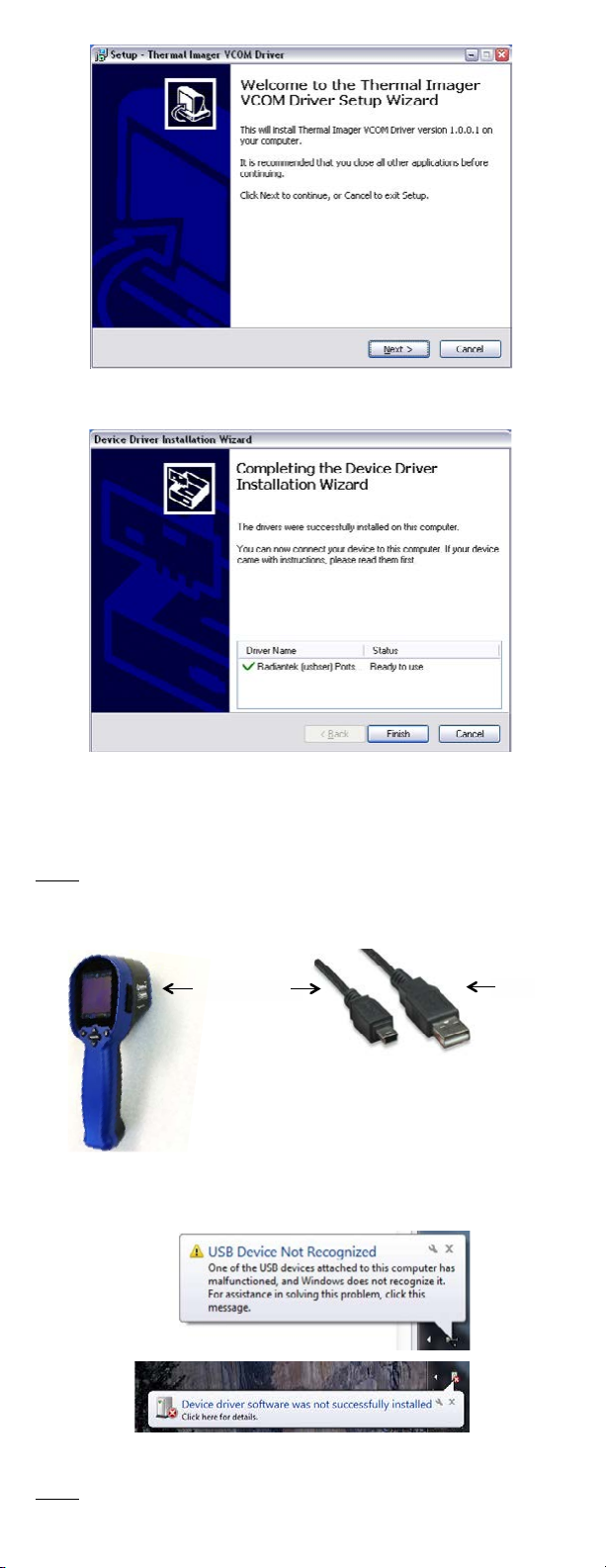
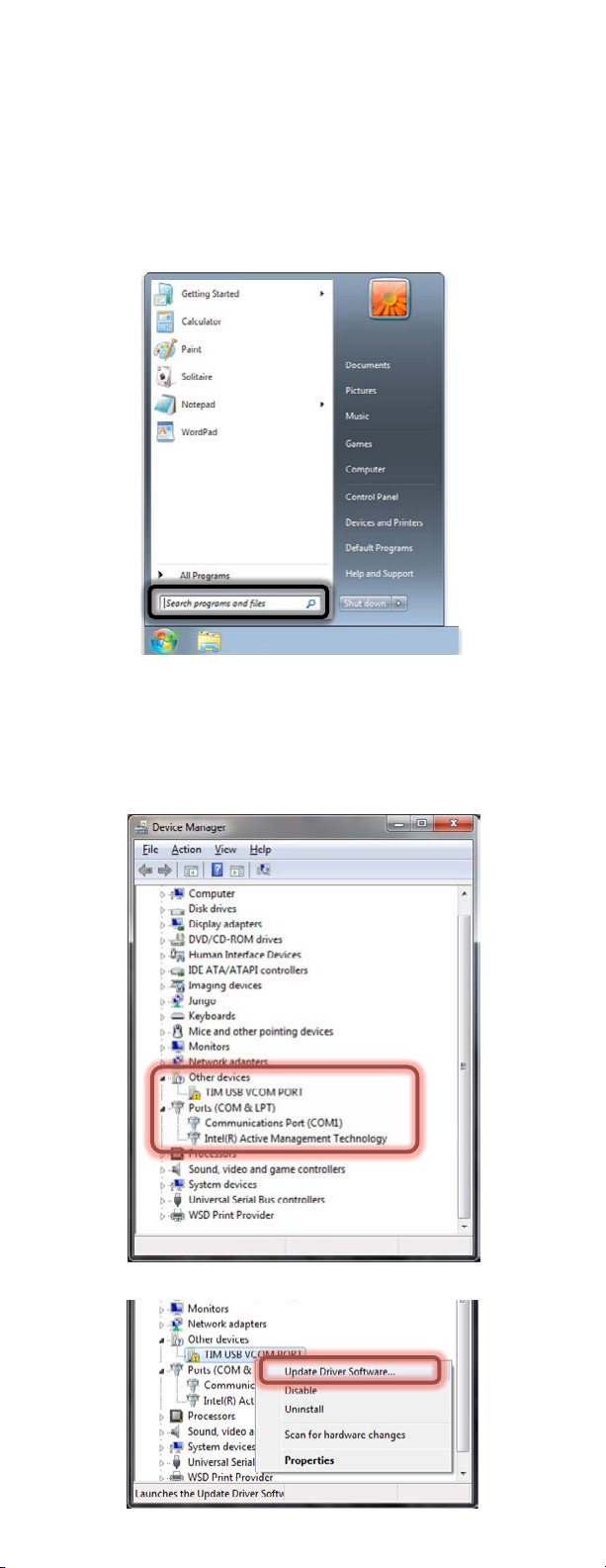
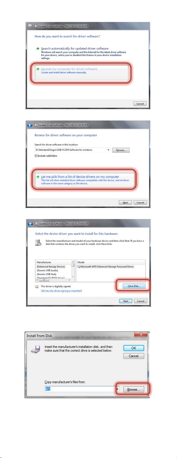
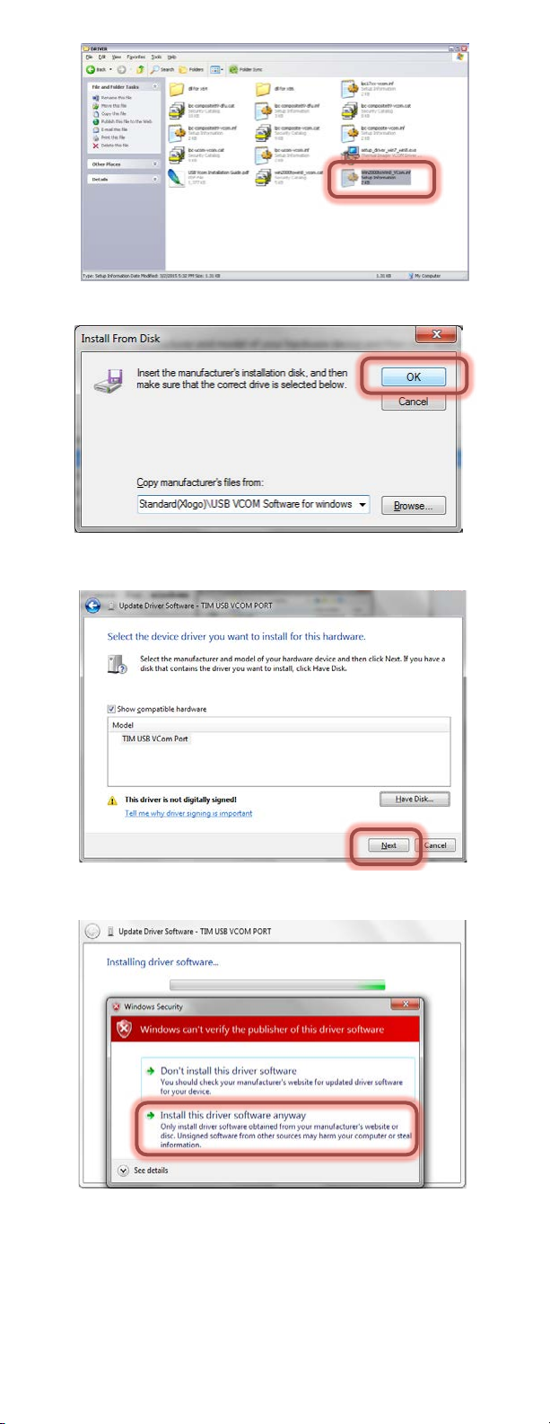
www.mastercool.com 54
function, then press Trigger (10) to confirm. Use the arrows to change the value. Press the
Trigger to save and Mode to return to normal functioning.
E The default emissivity is 0.95, or select other default emissivity: Matt:
0.95, Semi-matt: 0.8, Semi-glossy: 0.6, Glossy: 0.3
Select Set Value to adjust the emissivity (0.1 to 1, in 0.01 steps)
HAL You can select HAL or LAL to adjust the High Alarm ( HAL) or Low Alarm
(LAL) limits.
LAL
Power off The default setting is “Auto off 1 min”, you can select other default values:
5, 10, 20 minutes or “No auto off”. Manually power off the device by
pressing Mode Key (2) for 3 seconds.
Backlight Select low, middle or high
Set time Set the date and time in MM/DD/YYYY (month/day/year) and HH/MM/SS
(hour/minute/second) formats.
Time
stamp
Turn on Time Stamp to save thermal images with time stamp.
Turn off Time Stamp to hide date and time on stored thermal images.
Erase file Select All picture! to clear all stored thermal images.
Select All movie! to clear all stored videos.
Save
mode
Select Picture to save thermal images in image mode. (BMP and Excel
formats)
Select Movie to save thermal images in video mode.
Noise filter Turn on Filter to reduce noise in an image.
Turn off Filter to display real image noise.
STORAGE & CLEANING
The thermal imaging camera should be stored at room temperature. The sensor lens is
the most delicate part of the thermometer. The lens should be kept clean at all times, care
should be taken when cleaning the lens using only a soft cloth or cotton swab with water
or medical alcohol. Allowing the lens to fully dry before using the thermometer. Do not
submerge any part of the thermometer.
BATTERIES
The thermometer incorporates visual low battery indication as follows:
O
Op
pe
er
ra
at
ti
in
ng
g
M
Ma
an
nu
ua
al
l
f
fo
or
r
T
TI
IM
M0
03
3
T
Th
he
er
rm
ma
al
l
I
Im
ma
ag
ge
er
r
C
Ca
am
me
er
ra
a
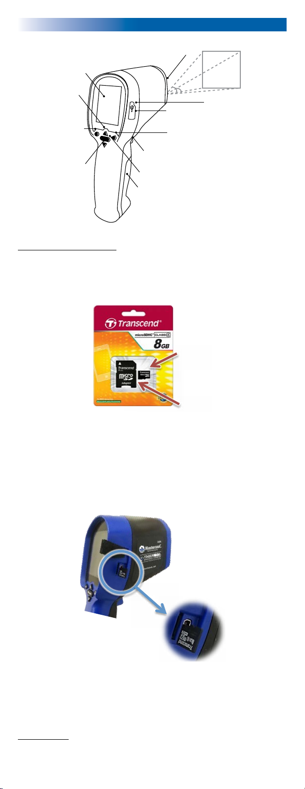
The thermal imager camera can measure from -20~250°C (-4~482°F) and displays the thermal image and temperature.
Furthermore, thermal images can be saved to a micro SD card. Transferring images to the software is included for image report
generation from these saved images.
OPERATION
1. Power on
Press Mode Key ( 2) or Trigger ( 10 ) to power on the unit.
2. Taking a thermal image and temperature
After power on, simply aim the thermal imager camera at the measure target with Lens
(9) and get the thermal image and temperature immediately. Please make sure the
target area is within the field of view.
Note: There are three cursors on the screen. The cross sign shows the temperature of
the object located in the middle of the screen. Other two moving cursors indicate the
highest and lowest temperatures in the thermal image.
3. Save thermal images
Press Trigger ( 10 ) to save the thermal image to the micro SD card, press Up Key ( 3) or
Down Key ( 4) to show the saved images. Press Mode Key ( 2) again to return to the
measurement screen.
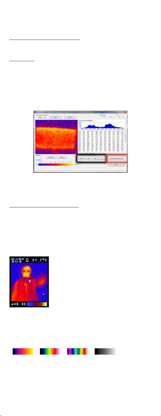
Press Color Palette Key ( 6) to select the color palette (4 selectable color palettes) to view thermal images.
5. C/°F/K
Press Unit Key ( 5) for C°F or K transferred.
6. Power off
Press Mode Key ( 2) for more than 5 sec. to power off the unit. Auto power off time is around 30 sec..
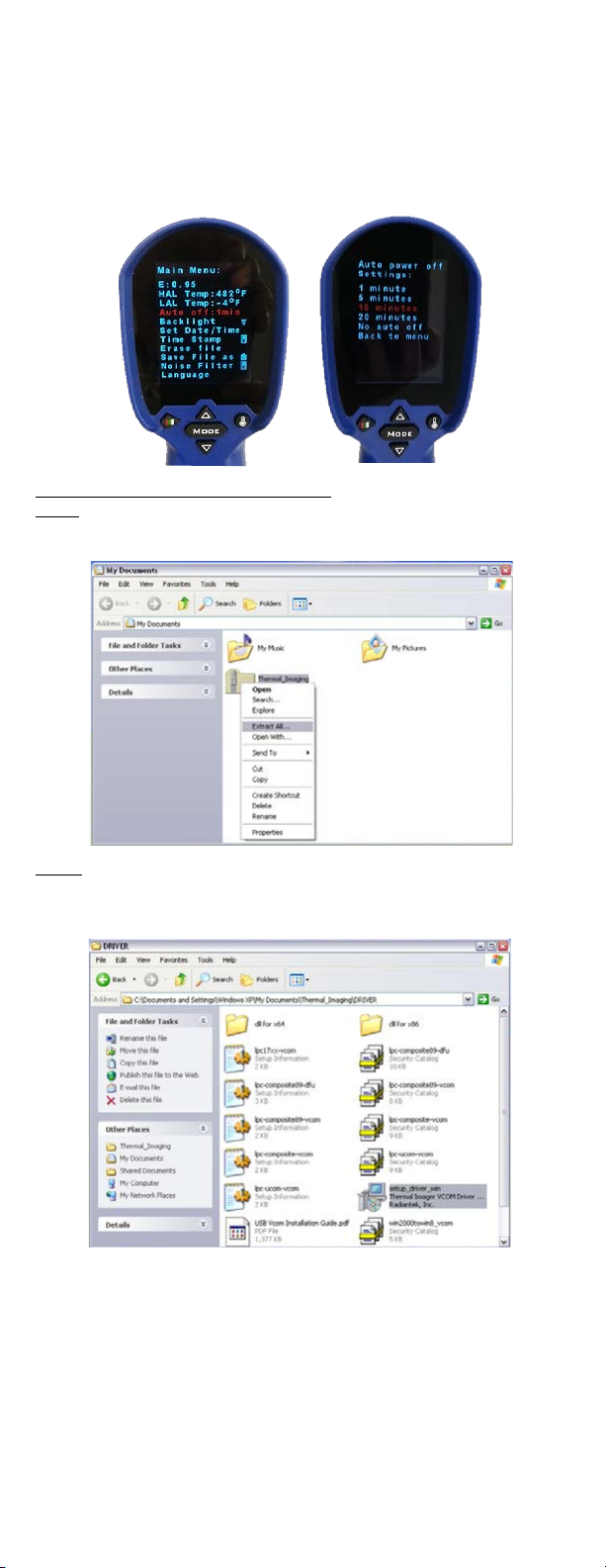
FUNCTIONS
Press Mode Key ( 2) for scrolling more display functions, then press Up key ( 3) or Down key ( 4) to change the
functions, then press Trigger ( 10 ) to confirm it.
Emissivity
Glossy:0.3
Select Set value to adjust the emissivity (0.1 to 1 step .01).
HAL You can select Set Min temp or Set Max item to adjust the High Alarm (HAL) or Lo Alarm (LAL) limits
(step .1).
LAL
Language Selectable Chinese or English.
Backlight Selectable 5 levels of brightness.
Set Time Set the date and time in MM/DD/YYYY (month/day/year) and HH/MM/SS (hour/minute/second) formats.
Time stamp Turn on Time stamp to save thermal images with real-time stamp.
Turn off Time stamp to hide date and time on stored thermal images.
Erase Image Select Yes, All image! to clear all stored thermal images.
Reset Select Reset to recover the factory setting data.
Set parameter
Select Use Median Value to reduce noise in an image.
Select No Filter to display real image noise.
STORAGE & CLEANING
It should be stored at room temperature. The sensor lens is the most delicate part of the thermometer. The lens should be kept
clean at all times, care should be taken when cleaning the lens using only a soft cloth or cotton swab with water or medical alcohol.
Allowing the lens to fully dry before using the thermometer. Do not submerge any part of the thermometer.
BATTERIES
The thermometer incorporates visual low battery indication as follows:
replaced, measurements are still possible
not possible
When the ‘Low Battery’ icon indicates the battery is low, the battery should be replaced immediately with AA, 1.5V batteries.
Please note: It is important to turn the instrument off before replacing the battery otherwise the thermometer may malfunction.
Dispose of used battery promptly and keep away from children.
SPECIFICATION
Thermal Image Resolution 32*31
Measurement Range -20~250°C (-4~482°F)
Accuracy (Tamb=20~26°C) 2% of reading, or 2°C(4°F) whichever is greater
Thermal Sensitivity 0.1°C
Frame Rate 9Hz
Field of View 40*40 deg
Emissivity Range 0.95 default – adjustable 0.1 to 1 step .01
Focus Focus free
LCD (inch) 2.8
LCD Type Color
Image Storage Stores up to 60000 images/GB, Bitmap (BMP) file format.
Memory Type Support 8G micro SD card
Sensor Filter (um) 8~14um
Interface USB
Battery Type AA*4
Battery Life (hr)(backlit) 6
Dimensions 94.65 x 74.03 x 233.68mm (3.73 x 2.91 x 9.20 inch)
Weight 411 grams(14.5 oz) including batteries (AA*4pcs)
EMC/RFI: Readings may be affected if the unit is operated within radio frequency electromagnetic field strength of approximately 3 volts per
meter, but the performance of the instrument will not be permanently affected.
* IP54 Splash Proof
O
Op
pe
er
ra
at
ti
in
ng
g
M
Ma
an
nu
ua
al
l
f
fo
or
r
T
TI
IM
M0
03
3
T
Th
he
er
rm
ma
al
l
I
Im
ma
ag
ge
er
r
C
Ca
am
me
er
ra
a
The thermal imager camera can measure from -20~250°C (-4~482°F) and displays the thermal image and temperature.
Furthermore, thermal images can be saved to a micro SD card. Transferring images to the software is included for image report
generation from these saved images.
OPERATION
1. Power on
Press Mode Key ( 2) or Trigger ( 10 ) to power on the unit.
2. Taking a thermal image and temperature
After power on, simply aim the thermal imager camera at the measure target with Lens
(9) and get the thermal image and temperature immediately. Please make sure the
target area is within the field of view.
Note: There are three cursors on the screen. The cross sign shows the temperature of
the object located in the middle of the screen. Other two moving cursors indicate the
highest and lowest temperatures in the thermal image.
3. Save thermal images
Press Trigger ( 10 ) to save the thermal image to the micro SD card, press Up Key ( 3) or
Down Key ( 4) to show the saved images. Press Mode Key ( 2) again to return to the
measurement screen.
Press Color Palette Key ( 6) to select the color palette (4 selectable color palettes) to view thermal images.
5. C/°F/K
Press Unit Key ( 5) for C°F or K transferred.
6. Power off
Press Mode Key ( 2) for more than 5 sec. to power off the unit. Auto power off time is around 30 sec..
FUNCTIONS
Press Mode Key ( 2) for scrolling more display functions, then press Up key ( 3) or Down key ( 4) to change the
functions, then press Trigger ( 10 ) to confirm it.
Emissivity
Glossy:0.3
Select Set value to adjust the emissivity (0.1 to 1 step .01).
HAL You can select Set Min temp or Set Max item to adjust the High Alarm (HAL) or Lo Alarm (LAL) limits
(step .1).
LAL
Language Selectable Chinese or English.
Backlight Selectable 5 levels of brightness.
Set Time Set the date and time in MM/DD/YYYY (month/day/year) and HH/MM/SS (hour/minute/second) formats.
Time stamp Turn on Time stamp to save thermal images with real-time stamp.
Turn off Time stamp to hide date and time on stored thermal images.
Erase Image Select Yes, All image! to clear all stored thermal images.
Reset Select Reset to recover the factory setting data.
Set parameter
Select Use Median Value to reduce noise in an image.
Select No Filter to display real image noise.
STORAGE & CLEANING
It should be stored at room temperature. The sensor lens is the most delicate part of the thermometer. The lens should be kept
clean at all times, care should be taken when cleaning the lens using only a soft cloth or cotton swab with water or medical alcohol.
Allowing the lens to fully dry before using the thermometer. Do not submerge any part of the thermometer.
BATTERIES
The thermometer incorporates visual low battery indication as follows:
replaced, measurements are still possible
not possible
When the ‘Low Battery’ icon indicates the battery is low, the battery should be replaced immediately with AA, 1.5V batteries.
Please note: It is important to turn the instrument off before replacing the battery otherwise the thermometer may malfunction.
Dispose of used battery promptly and keep away from children.
SPECIFICATION
Thermal Image Resolution 32*31
Measurement Range -20~250°C (-4~482°F)
Accuracy (Tamb=20~26°C) 2% of reading, or 2°C(4°F) whichever is greater
Thermal Sensitivity 0.1°C
Frame Rate 9Hz
Field of View 40*40 deg
Emissivity Range 0.95 default – adjustable 0.1 to 1 step .01
Focus Focus free
LCD (inch) 2.8
LCD Type Color
Image Storage Stores up to 60000 images/GB, Bitmap (BMP) file format.
Memory Type Support 8G micro SD card
Sensor Filter (um) 8~14um
Interface USB
Battery Type AA*4
Battery Life (hr)(backlit) 6
Dimensions 94.65 x 74.03 x 233.68mm (3.73 x 2.91 x 9.20 inch)
Weight 411 grams(14.5 oz) including batteries (AA*4pcs)
EMC/RFI: Readings may be affected if the unit is operated within radio frequency electromagnetic field strength of approximately 3 volts per
meter, but the performance of the instrument will not be permanently affected.
* IP54 Splash Proof
“Battery OK”:
Measurements are
possible
“Battery Low”:
Battery needs to be replaced,
measurements are still possible
“Battery Exhausted:
Measurements are not
possible
• When the ‘Low Battery’ icon indicates the battery is low, the battery should be replaced
immediately with 4 AA, 1.5V batteries.
• Please Note: It is important to turn the instrument off before replacing the battery
otherwise the thermometer may malfunction
• Dispose of used batteries properly and keep away from children.
SPECIFICATIONS:
Thermal Image Resolution: 32 x 31
Measurement Range: -20 to 250°C(4°F) whichever is greater
Accuracy(Tamb=20~26°C): ±2% of reading, or 2°C (4°F) whichever is greater
Thermal Sensitivity: 0.1°C
Frame Rate: 9Hz
Field of View: 40 x 40 deg
Emissivity Range: 0.95 default - adjustable 0.1 to 1 (in 0.01 steps)
Focus: Focus free
LCD (inch): 2.8
LCD type: Color
Image Storage: Store up to 25000 images/GB, BMP format.
Memory Type: Support 8G micro SD card
Spectral Range: 8.14um
Interface: USB
Battery Type: AA*4
Battery Life (with backlight): 6 hrs continuous use
Dimensions: 94.65 x 74.03 x 233.68 mm (3.73 x 2.91 x 9x20 inch)
Weight: 390 grams (13.8 oz) Including batteries (AA*4pcs)
EMC/CRFI: Reading may be affected if the unit is operated within radio frequency elec-
tromagnetic field strength of approximately 3 volts per meter, but the performance of the
instrument will not be permanently affected.