Master GHIBLI User manual

Questo dispositivo non protegge le tende in caso di forti e improvvise raffiche di vento.
Gentile cliente, la ringraziamo per aver acquistato un prodotto Master S.p.A. Prima di procedere all’installazione leggere attentamente questo manuale. Il dispositivo è stato
progettato per il comando di motori tubolari con finecorsa meccanici alimentati alla tensione di rete per la movimentazione di tende da sole, tapparelle e simili. Ogni altro uso al di fuori
dal campo definito da Master S.p.A. è vietato e comporta, così come il mancato rispetto delle istruzioni riportate in questo manuale, l'annullamento della responsabilità e della
garanzia Master S.p.A. L'installatore deve formare l'utilizzatore finale all'uso dell'automazione e fornirgli il presente manuale d’uso e manutenzione per eventuali successive
consultazioni.
In caso di rischi meteorologici di questo tipo, verificare che le tende restino chiuse! Master S.p.A. declina ogni responsabilità per danni verificatisi a causa di eventi atmosferici non
rilevati dal dispositivo.
Rispettare l’ambiente è un dovere di tutti! MASTER utilizza materiali di imballo
riciclabili. Al termine del ciclo di vita del prodotto smaltisci i materiali negli appositi
contenitori, secondo le norme vigenti sul territorio. Questo prodotto potrebbe
contenere sostanze inquinanti per l’ambiente e pericolose per la salute. E’
severamente vietato e pericoloso smaltire il prodotto gettandolo nei rifiuti
domestici.
Rispettiamo l’ambiente
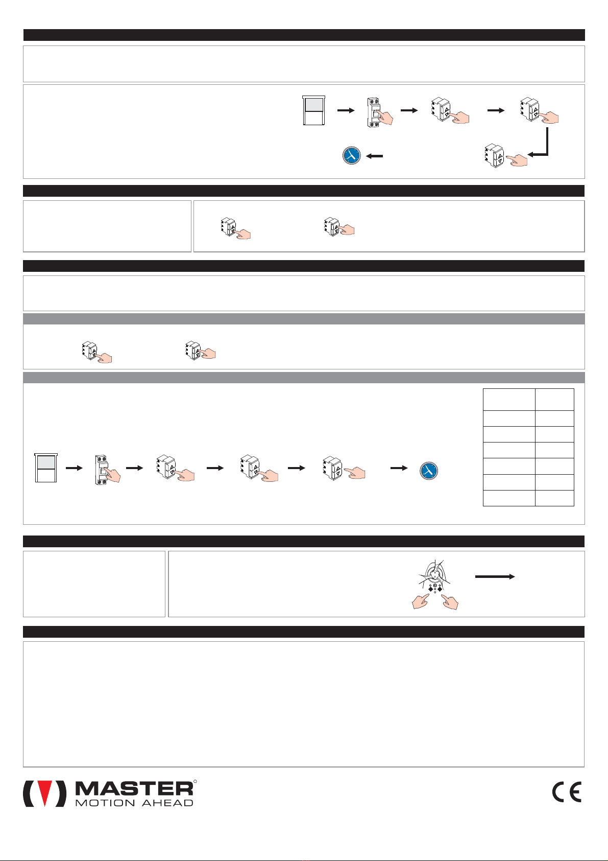
Soglia sole :(serie ZENITH) 1 klux - 45 klux
Alimentazione: 230 V~ 50 Hz
Grado di protezione: IPX4
Soglia vento: 10 km/h - 35 km/h
Temperatura di esercizio: –20°C - +55 °C
Portata max contatti: 1 x 2,6A / 2 x 2,6A
Peso: 200 g
Dimensioni: 236 x 54 x 73 mm
Caratteristiche tecniche
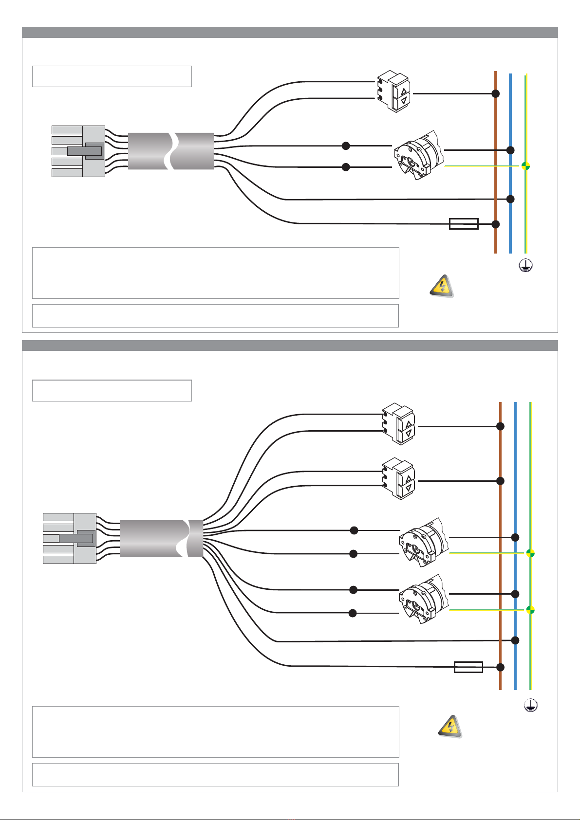
Effettuare i collegamenti in assenza di alimentazione Verificare che la linea di alimentazione non dipenda da circuiti elettrici destinati all’illuminazione Collegare sempre il motore
all'impianto di messa a terra (giallo/verde) Prevedere a monte della rete di alimentazione dell'automazione un dispositivo che assicuri la disconnessione completa onnipolare dalla
rete, con una distanza di apertura dei contatti in ciascun polo di almeno 3 mm. Tale dispositivo deve essere installato conformemente alle regole di installazione e deve essere collegato
direttamente ai morsetti di alimentazione Il prodotto non prevede alcuna protezione contro sovraccarichi o cortocircuiti. Prevedere sulla linea di alimentazione una protezione
adeguata al carico, ad esempio un fusibile di valore massimo 3,15 A (per GHIBLI e ZENITH) o 6,3A (per GHIBLI DUO e ZENITH DUO) La sezione dei cavi di collegamento deve
essere proporzionata alla lunghezza degli stessi ed all’assorbimento del carico, ed in ogni caso non inferiore ad 1,5 mm
● ●
●
●
●
●Utilizzare pulsanti di comando a posizioni momentanee
(a “uomo presente”), NON utilizzare deviatori a posizione mantenuta I pulsanti di comando sono connessi alla tensione di rete e quindi devono essere adeguatamente isolati e
protetti.
●
02. COLLEGAMENTI ELETTRICI
GHIBLI 2019
GHIBLI Duo 2019
centrale vento per 1 motore - 2 motori
ZENITH 2019
ZENITH Duo 2019
centrale sole/vento per 1 motore - 2 motori
rev05.3 27.05.2021
R
01. MONTAGGIO
L'installazione non corretta può causare gravi ferite Conservare queste istruzioni per eventuali interventi futuri di manutenzione e smaltimento del prodotto Tutte le operazioni di
installazione, collegamento, programmazione e manutenzione del prodotto devono essere effettuate esclusivamente da un tecnico qualificato e competente, rispettando le leggi, le
normative, i regolamenti locali e le istruzioni riportate in questo manuale Il cablaggio elettrico deve rispettare le norme CEI in vigore. La realizzazione dell'impianto elettrico definitivo è
riservato, secondo le disposizioni del D.M. 37/2008, esclusivamente all'elettricista Certe applicazioni richiedono il comando a «uomo presente» e possono escludere l'utilizzo di
comandi radio o necessitare di particolari sicurezze Per prevenire situazioni di potenziale pericolo, verificare periodicamente le condizione operative dell'avvolgibile
● ●
●
●
●
01.1 Avvertenze per la sicurezza
Leggere i dati tecnici riportati nel paragrafo “Caratteristiche tecniche” per valutare i limiti d'impiego del prodotto Prima di
installare il prodotto, verificarne la compatibilità con le apparecchiature e gli accessori associati Il motore collegato al
dispositivo deve essere del tipo a “finecorsa meccanici”, senza alcuna elettronica di controllo; il motore deve essere di potenza
adeguata al carico applicato (verificare i dati di targa riportati sul motore) Verificare che la confezione sia integra e non abbia
subito danni durante il trasporto L'urto violento e l'utilizzo di utensili non adeguati può causare la rottura di parti esterne o interne
del dispositivo È vietato forare o manomettere in alcun modo il dispositivo. Non modificare o sostituire parti senza
l'autorizzazione del costruttore Verificare che la superficie prescelta per l'installazione sia di materiale solido e possa garantire
un fissaggio stabile Installare il prodotto con le palette rivolte verso il basso e con il corpo del sensore orizzontale (l'uso di una
livella a bolla facilita l'operazione, l'attacco a muro basculante con angolo ±90° consente di fissare il sensore anche su strutture
non verticali) Il prodotto deve essere installato ben esposto al sole-vento, lontano da fonti di calore (es: canne fumarie), lontano
da ostacoli che possono interferire con il movimento delle palette Il cavo di alimentazione deve essere posizionato in modo tale
da non entrare in contatto con parti in movimento Non utilizzare prodotti abrasivi o solventi per la pulizia del prodotto, non
utilizzare pulitori a getto d’acqua o ad alta pressione Per la vostra sicurezza, è vietato operare in prossimità del rullo avvolgitore
a motore alimentato
●
●
●
●
●
●
●
●
●
●
●
Il prodotto non è destinato ad essere usato da persone (bambini compresi) le cui capacità fisiche, sensoriali o mentali siano
ridotte, oppure con mancanza di esperienza o di conoscenza, a meno che esse non abbiano potuto beneficiare, attraverso
l'intermediazione di una persona responsabile della loro sicurezza, di una sorveglianza o di istruzioni riguardanti l'uso del
prodotto Prima di azionare l'avvolgibile, assicurarsi che persone o cose non si trovino nell'area interessata dal movimento
dell'avvolgibile. Controllare l'automazione durante il movimento e mantenere le persone a distanza di sicurezza, fino al termine
del movimento Non permettere ai bambini di giocare con l'apparecchio e con i dispositivi di comando Non azionare
l'avvolgibile quando si stanno effettuando operazioni di manutenzione (es. pulizia vetri, ecc). Durante le manutenzioni scollegare
la linea di alimentazione
●
● ●
01.2 Avvertenze per l’installazione
01.3 Avvertenze per l’uso
MASTER S.p.A. via Pertini 3, 30030 Martellago (VE)
X
ATTENZIONE:
Installare il prodotto in orizzontale e con le
palette rivolte verso il basso
Funzionamento e Grado di protezione IP non
sono garantiti se il montaggio non avviene
secondo le indicazioni date
Nello scegliere la zona a cui fissare la centralina,
tenere conto che il sensore utilizzato nei modelli
ZENITH è sensibile alla luce solare: per
funzionare correttamente deve essere colpito dai
raggi solari; la sola luce non è sufficiente.
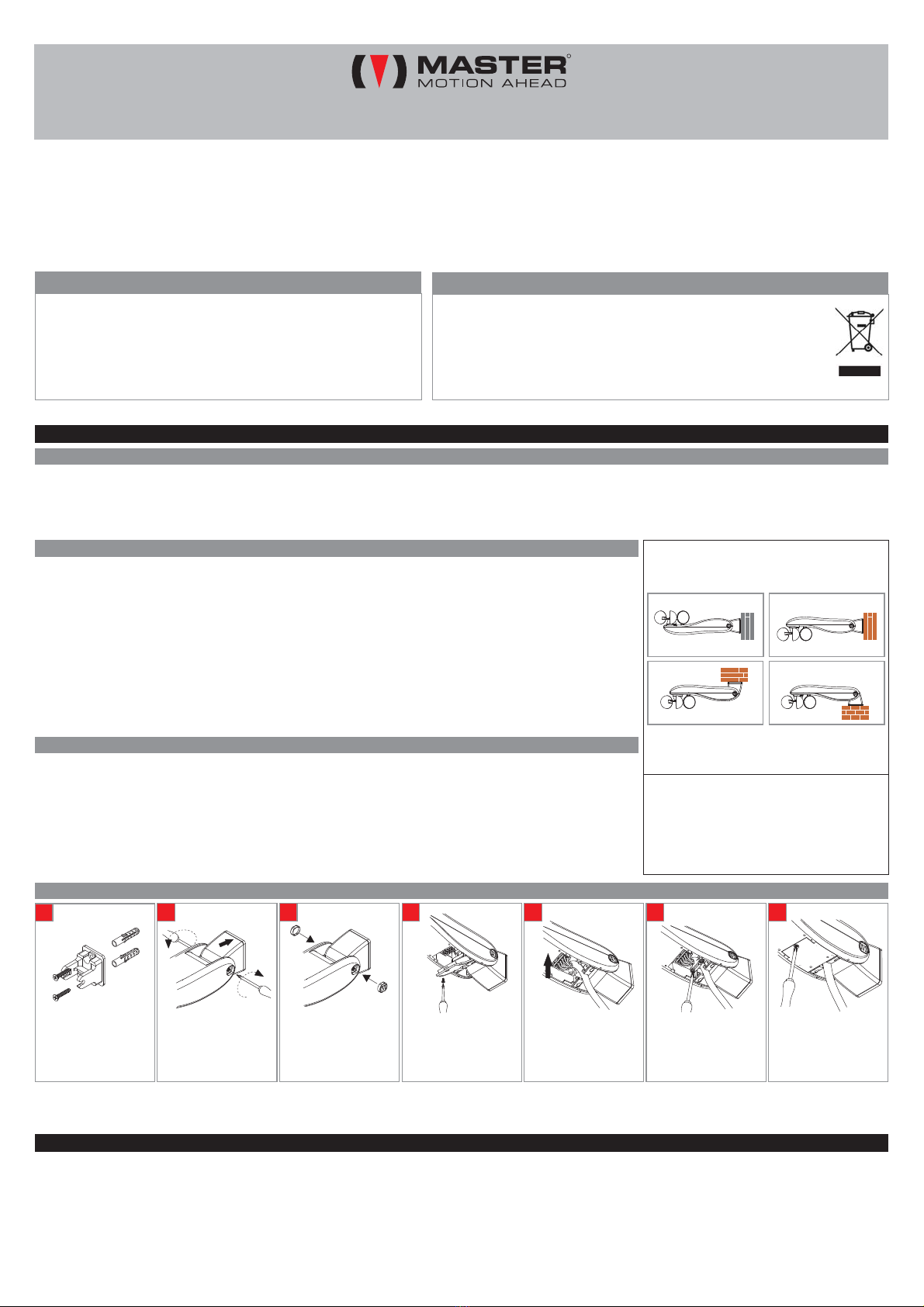
Indicazione per modelli ZENITH
Fissare il supporto con i
tasselli e le viti in
dotazione
A
Inserire il corpo sul
supporto e in
posizione orizzontale
chiudendo saldamente
le due viti laterali
bloccare
B
Applicare gli appositi
coperchi sulle due viti
laterali
C
Aprire il coperchio
sotto il sensore
D
Connettere il cavo in
dotazione: controllare
che il connettore sia
ben agganciato
E
Bloccare il cavo
utilizzando il ferma
cavo in dotazione
F
Chiudere il coperchio,
controllando che sia a
filo con il resto
dell’involucro
G
01.4 Montaggio
(1)
(1)ATTENZIONE: queste viti non devono mai essere svitate completamente.
Click!

02
02.1 COLLEGAMENTO GHIBLI - ZENITH
02.2 COLLEGAMENTO GHIBLI DUO - ZENITH DUO
connettore
cavo
GHIBLI 2019
ZENITH 2019
ALIMENTAZIONE
DI RETE
LN
5
comune
motore
messa a terra
comune pulsante
FUSIBILE
3,15A
MARRONE
BLU
NERO
NERO/BIANCO
ROSSO/BIANCO
ROSSO
Utilizzare pulsanti a posizioni momentanee
connettore
cavo
GHIBLI DUO 2019
ZENITH DUO 2019
ALIMENTAZIONE
DI RETE
LN
5
comune
motore
messa a terra
comune pulsante
FUSIBILE
6,3A
MARRONE
BLU
NERO
NERO/BIANCO
VERDE/BIANCO
VERDE
comune
motore
messa a terra
ROSSO/BIANCO
ROSSO
comune pulsante
GRIGIO
GRIGIO/BIANCO
ATTENZIONE: collegare esclusivamente motori muniti di dispositivi termici integrati (protetti termicamente)
Terminati i collegamenti elettrici, portare il motore (i motori) in posizione intermedia e verificare che in
condizione di “allarme vento” il modulo azioni il motore (i motori) in salita.
M1
M2
M1
M2
AVVERTENZA IN CASO DI SOSTITUZIONE VERSIONE PRECEDENTE
Nel caso in cui questa centralina Ghibli/Zenith debba sostituire una centralina
Ghibli/Zenith precedentemente installata, è possibile riutilizzare il cavo di quest’ultima (fili neri numerati)
operando la seguente modifica: collegare il comune del motore (filo BLU) al NEUTRO (come da
schema) e non più a FASE, come era riportato nello schema delle centraline prodotte prima del 2019.
versione 2019
Utilizzare pulsanti a posizioni momentanee
Terminati i collegamenti elettrici, portare il motore (i motori) in posizione intermedia e verificare che in
condizione di “allarme vento” il modulo azioni il motore (i motori) in salita.
AVVERTENZA IN CASO DI SOSTITUZIONE VERSIONE PRECEDENTE
Nel caso in cui questa centralina Ghibli/Zenith debba sostituire una centralina
Ghibli/Zenith precedentemente installata, è possibile riutilizzare il cavo di quest’ultima (fili neri numerati)
operando la seguente modifica: collegare il comune del motore (filo BLU) al NEUTRO (come da
schema) e non più a FASE, come era riportato nello schema delle centraline prodotte prima del 2019.
versione 2019
manovra1
manovra2
manovra1
manovra2
manovra1
manovra2

03. INTERFACCIAMENTO CON CENTRALI DOMOTICHE
b) La centrale domotica deve essere collegata al dispositivo come da schema, sostituendo i pulsanti di comando con le uscite di comando della centrale domotica.
Le uscite di comando della centrale domotica devono essere collegate agli ingressi pulsante del dispositivo sostituendo di fatto i pulsanti di comando manuale. Di conseguenza la
centrale domotica deve rispettare le regole di funzionamento dei pulsanti di comando, diverse a seconda che i pulsanti di comando funzionino a IMPULSO (impostazione di fabbrica)
o a UOMO PRESENTE (vedi sezione 07 «Logica pulsanti»).
Regole che la centrale domotica deve rispettare per comandare il dispositivo con pulsanti funzionanti a IMPULSO.
a) La centrale domotica NON DEVE misurare la corrente assorbita dagli ingressi pulsante (i quali assorbono correnti inferiori ad 1 mA).
c) Per azionare il motore, la centrale domotica deve chiudere il contatto (salita o discesa) per più di 0,5 secondi (tipicamente si utilizza un impulso di durata 1 secondo).
d) A contatti aperti, per arrestare il motore la centrale domotica deve chiudere un contatto (salita o discesa) per meno di 0,5 secondi (tipicamente si utilizza un impulso di durata 0,2
secondi).
Al momento della stampa di questo documento, non sono note particolari problematiche relative alla connessione tra prodotti MASTER e centrali domotiche (qualora si rispettino le
regole di cui sopra). Tuttavia MASTER declina ogni responsabilità riguardante la mancata compatibilità (anche parziale) con qualsivoglia centrale domotica. Se la centrale domotica
utilizza protocolli KNX o simili, contattare il fornitore della centrale domotica informandolo delle regole sopra riportate. E’ probabile che il produttore della centrale domotica possa
fornire adeguate interfacce per connettere il dispositivo alla centrale domotica.
a) La centrale domotica NON DEVE misurare la corrente assorbita dagli ingressi pulsante (i quali assorbono correnti inferiori ad 1 mA).
b) La centrale domotica deve essere collegata al motore come da schema, sostituendo i pulsanti di comando con le uscite di comando della centrale domotica.
Regole che la centrale domotica deve rispettare per comandare il dispositivo con pulsanti funzionanti a UOMO PRESENTE.
d) Per arrestare il motore, la centrale domotica deve essere in grado di riaprire i contatti di salita/discesa in qualsiasi momento.
c) Per permettere il completamento dell’intera manovra di apertura/chiusura, la centrale domotica deve essere in grado di chiudere il contatto di salita/discesa per il tempo
necessario al motore a compiere la manovra completa di apertura/chiusura.
03
04. SEGNALAZIONI VISIVE
La segnalazione di «allarme vento» (LED MANOVRA rosso lampeggiante veloce) non può essere
disattivata. Tutte le altre segnalazioni possono essere disattivate. Per abilitare/disabilitare le segnalazioni:
02. Rilascia i pulsanti. I LED si spengono. L’impostazione è stata modificata.
01. Premi assieme P1 e P2 per 5 secondi, finché i LED rimangono accesi.
04.1 ABILITARE-DISABILITARE LE SEGNALAZIONI VISIVE
P2
P1 secondi
5
05. FUNZIONE VENTO
Se l'intensità del vento è superiore alla soglia impostata per almeno 3 secondi, viene eseguita una manovra di salita a protezione della tenda da sole (allarme vento). Durante questa
fase . La centrale esce dalla condizione di “allarme vento” se per almeno 8 minuti l'intensità del vento si mantiene inferiore alla soglia impostata.
La soglia vento è variabile da 10 a 35 Km/h. La fabbrica imposta la soglia vento a 15 Km/h. Durante l’installazione è possibile uscire dall’allarme vento premendo brevemente (meno di
1 secondo) uno dei pulsanti P1, P2, P3 del dispositivo. Per modificare la soglia:
tutti i comandi manuali sono inibiti
05. Entro 15 secondi, premi brevemente e velocemente SU il numero di volte pari alla soglia desiderata (vedi Tab. 1).
06. Attendi qualche secondo. Il motore segnala la soglia corrente (vedi Tab. 1).
04. Entro 15 secondi, premi brevemente e velocemente 2 volte GIU. Il motore segnala la soglia corrente (vedi Tab. 1).
03. Entro 15 secondi, premi brevemente e velocemente 8 volte GIU. Il motore effettua 3 movimenti in salita.
01. Porta il motore in posizione intermedia.
02. Togli tensione, attendi qualche secondo, alimenta nuovamente.
Attendi
12
39
6
2 x GIU
ON
8 x GIU premi SU da 1 a 6 volte
(vedi Tab. 1)
Numero
movimenti Soglia
1
2
3
4
5
6
10 Km/h
15 Km/h
20 Km/h
25 Km/h
30 Km/h
35 Km/h
Tab. 1 - Soglia Vento
Led VENTO
Pulsante P1
Led SOLE
Pulsante P2
Led MANOVRA
Pulsante P3
GHIBLI - GHIBLI DUO
spento: alla fine dell’allarme vento la tenda non scenderà
automaticamente : alla fine dell’allarme vento la
tenda scenderà automaticamente : «funzione
discesa automatica» non abilitata o allarme vento
●verde
●rosso
spento rosso: vento sotto soglia : vento sopra soglia
●
LED SOLE
LED MANOVRA
verde: è stata eseguita una manovra di discesa automatica
●lampeggiante veloce: allarme vento
LED VENTO
ZENITH - ZENITH DUO
LED SOLE
LED MANOVRA
spento
verde
lampeggiante lento
: ultima manovra automatica eseguita: «salita» ●
: ultima manovra automatica eseguita: «discesa» ●
: centrale appena accesa o appena
uscita da «allarme vento» : allarme
vento
●lampeggiante veloce
spento verde: sole sotto soglia : sole sopra soglia
●
●: «funzione sole» disabilitata o allarme ventorosso
LED VENTO
spento rosso: vento sotto soglia : vento sopra soglia
●
06. TEST ANEMOMETRICO
Il dispositivo è provvisto di una funzione di diagnosi sulla funzionalità del sensore vento. Se per 24 ore circa il sensore vento non genera alcun impulso valido, il sensore forza la salita a
scatti della tenda da sole, sospende ogni altra attività e segnala l'anomalia facendo lampeggiare i LED. Il dispositivo uscirà da questo stato riprendendo le normali attività solo quando
giungerà un impulso valido dall'anemometro. La fabbrica imposta il test anemometrico ad “inattivo”. Per modificare l'impostazione:
01. Porta il motore in posizione intermedia.
02. Togli tensione, attendi qualche secondo, alimenta nuovamente.
03. Entro 15 secondi, premi brevemente e velocemente 8 volte GIU.
04. Entro 15 secondi, premi brevemente e velocemente 5 volte SU.
Il motore effettua 3 movimenti in salita.
Il motore segnala: 1 su = funzione attiva, 1 giù = funzione inattiva.
05. Entro 15 secondi:
Per disattivare: premi brevemente GIU.
Per attivare: premi brevemente SU.
06. Attendi qualche secondo.
Il motore segnala: 1 su = funzione attiva, 1 giù = funzione inattiva.
Attendi
12
39
6
5 x SU
ON
8 x GIU
per disattivare: premi GIU
per attivare: premi SU
FATTO!

04
08. FUNZIONE DISCESA AUTOMATICA (solo GHIBLI e GHIBLI DUO)
Se la funzione è attiva e se l'ultima manovra
effettuata prima dell'ingresso in allarme vento è stata
DISCESA, all'uscita dall'allarme vento il dispositivo
comanda una manovra automatica di discesa. La
fabbrica imposta questa funzione ad “inattiva”. Per
modificare questa impostazione:
4 x GIU
4 x GIU
Per Attivare
Per Attivare
I pulsanti devono essere premuti brevemente
e velocemente. ll motore segnala la modifica
dell’impostazione con un breve movimento
su/giù
I pulsanti devono essere premuti brevemente e velocemente. ll motore
segnala la modifica dell’impostazione con un breve movimento su/giù
4 x SU
4 x SU
Per Disattivare
Per Disattivare
09. FUNZIONE SOLE (solo ZENITH e ZENITH DUO)
Se l'intensità del sole è superiore alla soglia impostata per almeno 2.5 minuti, viene eseguita una manovra automatica di discesa; quando l'intensità del sole ritorna ad essere inferiore
alla soglia impostata per almeno 18 minuti, viene eseguita una manovra automatica di salita. Una volta eseguita una manovra automatica di discesa per presenza di sole, la
successiva manovra automatica eseguita dalla centrale sarà quella di salita per assenza di sole e così via. L'utilizzatore può in ogni caso azionare la tenda da sole, senza che il
comando manuale incida sulla logica di funzionamento del sensore sole. La soglia sole è variabile da 1 a 45 Klux. La fabbrica imposta la soglia sole a 15 Klux.
06. Attendi qualche secondo. Il motore segnala la soglia corrente (vedi Tab. 2).
05. Entro 15 secondi, premi brevemente e velocemente SU il numero di volte pari alla soglia desiderata (vedi Tab. 2).
01. Porta il motore in posizione intermedia.
04. Entro 15 secondi, premi brevemente e velocemente 3 volte SU. Il motore segnala la soglia corrente (vedi Tab. 2).
02. Togli tensione, attendi qualche secondo, alimenta nuovamente.
03. Entro 15 secondi, premi brevemente e velocemente 8 volte GIU. Il motore effettua 3 movimenti in salita.
Attendi
12
39
6
3 x SU
ON
8 x GIU premi SU da 1 a 6 volte
(vedi Tab. 2)
Numero
movimenti Soglia
1
2
3
4
5
6
01 Klux
08 Klux
15 Klux
22 Klux
30 Klux
45 Klux
Tab. 2 - Soglia Sole
07. LOGICA PULSANTI
I pulsanti di comando possono funzionare in logica IMPULSO oppure in logica UOMO PRESENTE.
La fabbrica imposta il dispositivo per lavorare in logica IMPULSO. Per modificare questa impostazione:
UOMO PRESENTE: per muovere il motore premere un pulsante per almeno 0,5 secondi, per arrestare il motore rilasciare il pulsante.
IMPULSO: per muovere il motore premere un pulsante per almeno 0,5 secondi, per arrestare il motore premere brevemente (meno di 0,5 secondi) uno dei due pulsanti.
02. Togli tensione, attendi qualche secondo, alimenta nuovamente.
Il motore segnala: 1 su = uomo presente, 1 giù = impulso.
Per selezionare «impulso»: premi brevemente GIU.
04. Entro 15 secondi, premi brevemente e velocemente 4 volte GIU.
05. Entro 15 secondi:
Il motore effettua 3 movimenti in salita.
03. Entro 15 secondi, premi brevemente e velocemente 8 volte GIU.
Il motore segnala: 1 su = uomo presente, 1 giù = impulso.
Per selezionare «uomo presente»: premi brevemente SU.
06. Attendi qualche secondo.
01. Porta il motore in posizione intermedia.
Attendi
12
39
6
4 x GIU
ON
8 x GIU
impulso: premi GIU
uomo presente: premi SU
10. RIPRISTINO DELLE CONDIZIONI DI FABBRICA (reset)
Questa procedura riporta il dispositivo
ricevente alle condizioni di fabbrica. Questa
procedura deve essere effettuata
esclusivamente da personale tecnico
qualificato. Una volta effettuato il «reset», il
tecnico deve installare nuovamente questo
dispositivo e verificarne il corretto
funzionamento.
01. Premi assieme P1 e P3.
02. Mantieni premuti P1 e P3 per 30 secondi, finché i LED
rimangono accesi fissi.
Dopo qualche secondo i LED iniziano a lampeggiare.
03. Il motore compie una segnalazione. Reset effettuato!! P3P1 secondi
30
All rights reserved.
R
Tutti i prodotti e le specifiche tecniche citati in questo documento sono soggetti a variazioni senza preavviso. Il costruttore non può essere considerato responsabile per eventuali danni derivanti da usi impropri,
erronei o irragionevoli. Con la presente MASTER SpA dichiara che questo dispositivo è conforme ai requisiti essenziali ed alle altre disposizioni pertinenti stabilite dalla direttive. La dichiarazione di conformità può
11. COSA FARE SE...
●● ●La centrale è in allarme vento. La soglia sole potrebbe essere troppo alta. Regolare la soglia. La centrale potrebbe essere poco esposta al sole, oppure qualche ostacolo
potrebbe impedire il corretto rilevamento del sole. La funzione sole potrebbe essere disattivata. Il sensore sole potrebbe essere danneggiato. Verificarne il funzionamento.
●●
●La funzione «discesa automatica» è attiva e l’ultima manovra prima dell’ingresso della centrale in allarme vento è stata DISCESA.
(solo ZENITH e ZENITH DUO) In presenza di sole non viene comandata la discesa.
(solo GHIBLI e GHIBLI DUO) All’uscita da «allarme vento» il motore si muove in discesa.
●Il collegamento dei fili del motore è invertito.
In presenza di vento non viene comandata la salita.
● ● ●La soglia vento potrebbe essere troppo alta. Regolare la soglia. La centrale potrebbe essere installata in posizione poco esposta al vento. Il sensore potrebbe essere
danneggiato. Verificarne il funzionamento facendo ruotare le palette per verificare che la centrale entri in «allarme vento».
Quando si preme il pulsante SALITA, il motore si muove in DISCESA.
La centrale non effettua alcuna operazione.
●●Verificare che la centrale sia correttamente installata. Non appena alimentata, la centrale accende brevemente i LED, se ciò non avviene può essere necessaria la sostituzione
della centrale.
RESET
EFFETTUATO
09.2 COME REGOLARE LA SOGLIA SOLE
09.1 ATTIVARE-DISATTIVARE LA FUNZIONE SOLE

GHIBLI 2019
GHIBLI Duo 2019
wind device for 1 motor - 2 motors
ZENITH 2019
ZENITH Duo 2019
sun/wind device for 1 motor - 2 motors
rev05.3 27.05.2021
R
Dear customer, thank you for purchasing a MASTER product. This guide contains information about the product use. Before the product installation and use, please read carefully this
guide and keep it for future reference. The device is designed for the control of tubular motors with mechanical limit switch for moving awnings and the like. Any other use beyond the
field defined by Master S.p.A. is prohibited and involves, as well as the failure to comply with instructions provided in this guide, the cancellation of Master S.p.A. liability and warranty.
The installer, after the installation of the product, must teach the end user about the working way of the automation and provide him with the user manual.
This sensor does not protect awning in case of strong and sudden gusts of wind. In case of weather hazards of this type, make sure that the curtains remain closed! Master
S.p.A. declines all responsibility for damage incurred due to weather events not detected by the device.
MASTER uses packaging recyclable materials. Dispose materials on the
proper containers, complying with the law in force in your locality.
This product may have substances that are polluting for the environment and
dangerous for the health.
At the end of the product life cycle, carefully comply with the waste disposal
rules. It is strictly forbidden to dispose the product on the domestic waste.
Disposal
Power supply: 230 V~ 50 Hz
Max contact flow rate: 1 x 2,6A / 2 x 2,6A
Dimensions: 236 x 54 x 73 mm
Weight: 200 g
Working temperature: –20°C -+55 °C
Protection grade: IPX4
Wind threshold: 10 km/h - 35 km/h
Sun threshold :(ZENITH series) 1 klux - 45 klux
Technical specifications
Make connections with power supply disconnected Check that the power supply does not depend from electrical circuits for lighting Always connect the motor to the grounding
system (yellow/green) The supply line must be equipped with a circuit breaker. The supply line must be fitted with a device with a voltage category III, i.e. the distance between the
contacts must be of 3,5 mm at least The product doesn’t not provide any protection against overloads or short circuits. Provide the supply line with an adequate protection to the load,
for example a fuse of maximum value 3,15 A (GHIBLI and ZENITH) or 6,3 A (GHIBLI DUO and ZENITH DUO) The section of the connecting cables must be proportionate to their
length and to the absorption of the load, and in any case not less than 1,5 mm , do not use buttons with maintained position
Command buttons are subject to the mains voltage and therefore must be properly insulated and protected
● ●
●
●
●
● ●
You must use momentary (hold-to-run) button
02. ELECTRICAL CONNECTIONS
01. MOUNTING
Incorrect installation can cause serious injuries Keep these instructions for future maintenance work and disposal of the product All the product installation, connection,
programming and maintenance operations must be carried out only by a qualified and skilled technician, who must comply with laws, provisions, local regulations and the instructions
given in this manual The wiring must comply with current IEC standards. The final electrical system must be created only by the electrician Some applications require hold-to-run
operation and can exclude the use of radio controls or require particular safety devices To prevent potentially dangerous situations, check the operating condition of the roller
shutter/awning regularly
● ●
● ●
●
01.1 Warning for safety
Read the technical specifications on the paragraph “Technical specifications” to evaluate the operating limits of the product
Before installing the product, check the compatibility with the associated devices and accessories The motor connected to the
device must be of the type "mechanical limit switches", without any electronic control. The motor must be of adequate power to
the load (check the nameplate data on the motor) Check that the package is intact and has not been damaged in transit A
heavy shock and the use of unsuitable tools can cause the damage of the external or internal parts of the product Do not
pierce or tamper with the product in any way. Do not modify or replace parts without the manufacturer’s permission Check that
the place chosen for the installation is made by solid material and can ensure a stable fixation Install the product with the cups
pointing downwards and with the body of the sensor horizontally (using a bubble level facilitates the operation, the attack on the
wall with tilting angle ± 90 ° allows you to mount the sensor on non-vertical structures) The product must be installed well
exposed to the sun-wind, away from heat sources (eg chimneys), away from obstacles that may interfere with the movement of
the cups The power cable must be positioned in such a way that it does not come into contact with moving parts Do not use
abrasive or solvent product for cleaning the device; do not clean using water or high-pressure cleaners For your safety, do not
work near the winding roller while the motor is powered
●
●
● ●
●
●
●
●
● ●
●
The product is not intended to be used by persons (including children) with reduced physical, sensory or mental capabilities, or
lack of experience and knowledge, unless they are supervised or given instructions about the product way of use by a person
responsible for their safety Check the automation during the movement and keep people at a safe distance, until the
movement ends Do not allow children to play with the appliance or with the fixed control devices Do not operate the blind
when maintanance operations are being carried out (e.g. window cleaning, etc.). If the control device is automatic, disconnect
the motor from the power line
●
● ●
01.2 Warning for installation
01.3 Warning for use
X
CAUTION:
Install the product horizontally and with the
cups facing downwards
Operation and IP protection grade are not
guaranteed if assembly does not take place
according to the indications given
Indication for ZENITH models
When choosing the zone to fix the control unit,
keep in mind that the sensor used in the
ZENITH models is sensitive to sunlight: in order
to function correctly it must be hit by the sun's
rays; the only light is not enough.
01.4 Mounting
(1) this screws must never be completely unscrewedWARNING:
Fix the wall support
using the supplied
plugs and screws
A
Insert the body on the
support and lock in a
horizontal position by
firmly closing the two
side screws
B
Apply the appropriate
covers on the two side
screws
C
Open the closing cover
placed under the
sensor
D
Connect the supplied
cable: check that the
connector is securely
connected
E
Lock the cable using
the supplied cable
holder
F
Close the lid, checking
that it is flush with the
rest of the casing
G
(1)
Click!
MASTER S.p.A. via Pertini 3, 30030 Martellago (VE)

02
02.1 ELECTRICAL CONNECTION GHIBLI - ZENITH
02.2 ELECTRICAL CONNECTION GHIBLI DUO - ZENITH DUO
connector
cable
GHIBLI 2019
ZENITH 2019
MAIN POWER
SUPPLY
LN
5
common
of motor
ground
common of button
FUSE
3,15A
BROWN
BLUE
BLACK
BLACK/WHITE
RED/WHITE
RED
You must use momentary (hold-to-run) button
connector
cable
GHIBLI DUO 2019
ZENITH DUO 2019
MAIN POWER
SUPPLY
LN
5
common
of motor
ground
common of button
FUSE
6,3A
BROWN
BLUE
BLACK
BLACK/WHITE
GREEN/WHITE
GREEN
common
of motor
ground
RED/WHITE
RED
common of button
GREY
GREY/WHITE
CAUTION: only connect motors equipped with integrated thermal devices (thermally protected)
M1
M2
M1
M2
Check the connections: bring the motor/motors to the intermediate position and check that in the “wind alarm”
condition the module commands the upward movement to the motor/motors
WARNING IN CASE OF REPLACEMENT OF THE PREVIOUS VERSION
In the event that this Ghibli / Zenith version 2019 control unit needs to replace a previously installed
Ghibli / Zenith control unit, it is possible to reuse the latter's cable (numbered black wires) by making the
following modification: connect the common of motor (BLUE wire) to NEUTRAL (as in the diagram) and
no longer to PHASE, as was shown in the diagram of the control units produced before 2019.
You must use momentary (hold-to-run) button
CAUTION: only connect motors equipped with integrated thermal devices (thermally protected)
Check the connections: bring the motor/motors to the intermediate position and check that in the “wind alarm”
condition the module commands the upward movement to the motor/motors
WARNING IN CASE OF REPLACEMENT OF THE PREVIOUS VERSION
In the event that this Ghibli / Zenith version 2019 control unit needs to replace a previously installed
Ghibli / Zenith control unit, it is possible to reuse the latter's cable (numbered black wires) by making the
following modification: connect the common of motor (BLUE wire) to NEUTRAL (as in the diagram) and
no longer to PHASE, as was shown in the diagram of the control units produced before 2019.
manoeuvre1
manoeuvre2
manoeuvre1
manoeuvre2
manoeuvre1
manoeuvre2

03. INTERFACING WITH HOME AUTOMATION CONTROL UNIT
a) The H.A.C.U. must not measure the current drawn by the command inputs of the device (which absorb less than 1 mA).
d) To stop the motor, the H.A.C.U. must close contact (up or down) for 0.5 seconds or less (typically using a pulse duration of 0.2 seconds).
c) To operate the motor, the H.A.C.U. must close contact (up or down) for more than 0.5 seconds (typically using a pulse duration of 1 second).
Rules that the H.A.C.U. must comply to control the device operating with buttons in PULSE mode.
b) The H.A.C.U. must be connected to the device as shown, substituting the command buttons with the outputs of the H.A.C.U..
The control outputs of the HomeAutomation Control Unit (following H.A.C.U.) must be connected to the command inputs of the device, replacing the manual buttons. Consequently,
the H.A.C.U. must comply with the rules of operation of the command buttons, depending on whether the command buttons work in PULSE mode (factory setting) or in HOLD TO
RUN mode (see section 07 " Logic of commands").
At the time of this document printing, specific issues related to the connection between MASTER products and H.A.C.U. are not known (if you follow the rules above). However
MASTER disclaims any responsibility concerning the non-compatibility (even partial) with any H.A.C.U.. If the H.A.C.U. uses KNX protocols or similar, contact the vendors of home
automation controller informing them of the rules above. Probably the manufacturer of H.A.C.U. can provide appropriate interfaces to connect the device to the H.A.C.U..
Rules that the H.A.C.U. must comply to control the device operating with buttons in HOLD TO RUN mode.
c) To allow the conclusion of the entire opening / closing, the H.A.C.U. must be able to close the contact UP / DOWN to the time required for the motor to perform the complete
operation.
b) The H.A.C.U. must be connected to the device as shown, substituting the command buttons with the outputs of the H.A.C.U..
a) The H.A.C.U. must not measure the current drawn by the command inputs of the device (which absorb less than 1 mA).
d) To stop the motor, the H.A.C.U. must be able to re-open the contacts UP/ DOWN at any time.
03
04. VISUAL SIGNALS
The signal of "wind alarm" (LED MANOEUVRE quickly flashing) can not be disabled. All other signals can be
disabled. To enable / disable the signals:
01. Press togheter P1 and P2 for 5 seconds until the LEDs will stay on.
02. Release the buttons. The LEDs switch off.The setting has been changed.
04.1 HOW TO ENABLE-DISABLE THE VISUAL SIGNALS
P2
P1 5
seconds
05. WIND FUNCTION
If the wind speed is above the set threshold for at least 3 seconds, an upward manoeuvre is performed to protect the awning (wind alarm). During this phase, all manual controls are
inhibited. The device exits from the condition of "wind alarm" if for at least 8 minutes the wind speed remains below the threshold set. The wind threshold is variable from 10 to 35 Km /
h. The factory sets the threshold wind at 15 km / h. During installation you can exit by the alarm wind by pressing briefly (less than 1 second) one of the buttons P1, P2, P3 of the device.
To change the threshold:
04. Within 15 seconds, press DOWN 2 times (briefly and quickly). The motor signals the current threshold (see Tab. 1).
05. Within 15 seconds press UP, briefly and quickly, the number of times equal to the desired threshold (see Tab. 1).
01. Bring the motor in an intermediate position.
02. Disconnect power supply, wait a few seconds; connect power supply.
06. Wait a few seconds. The motor signals the new threshold (see Tab. 1).
03. Within 15 seconds, press DOWN 8 times (briefly and quickly). The motor performs 3 upward movements.
Wait
12
39
6
2 x DOWN
ON
8 x DOWN press UP from 1 to 6 times
(see Tab. 1)
N° of
movements Setting
1
2
3
4
5
6
10 Km/h
15 Km/h
20 Km/h
25 Km/h
30 Km/h
35 Km/h
Tab. 1 - Wind threshold
Led WIND
Button P1
Led SUN
Button P2
Led MANOEUVRE
Button P3
GHIBLI - GHIBLI DUO
off: the function is active, but the last operation performed
was not «DOWN» : at the end of the wind alarm an
automatic downward movement will be performed : the
AUTOMATIC LOWERING function is not active or wind
alarm
●green
●red
LED SUN
LED MANOEUVRE
green: an AUTOMATIC LOWERING manoeuvre was
performed : wind alarmquickly flashing
●
off red: wind below threshold : wind above threshold●
LED WIND
ZENITH - ZENITH DUO
off green: last automatic manoeuvre performed: «up» :
last automatic manoeuvre performed: «down»
●
●slowly
flashing: the device is just turned on or is just exit from wind
alarm : wind alarm
●quickly flashing
LED MANOEUVRE
off green: sun below threshold : sun above threshold
●
●red: «sun function» is not active or wind alarm
LED SUN
off red: wind below threshold : wind above threshold
●
LED WIND
06. ANEMOMETRIC TEST
The device is provided with a diagnosis function of the wind sensor. If, for about 24 hours the wind sensor does not generate any valid pulse, the device commands an automatic
upward manoeuvre, suspends all other activities and indicates the fault by flashing the LEDs. The device will come out of this state resuming normal activities only when the wind
sensor generates a valid pulse. The factory sets this test "inactive". To change the setting:
05. Within 15 seconds:
to activate: press UP (briefly)
04. Within 15 seconds, press UP 5 times (briefly and quickly).
The motor signals: 1 UP = function active, 1 DOWN = function inactive
06. Wait a few seconds.
03. Within 15 seconds, press DOWN 8 times (briefly and quickly).
to deactivate: press DOWN (briefly)
02. Disconnect power supply, wait a few seconds; connect power supply.
The motor performs 3 upward movements.
01. Bring the motor in an intermediate position.
The motor signals: 1 UP = function active, 1 DOWN = function inactive
Wait
12
39
6
5 x UP
ON
8 x DOWN
To deactivate: press DOWN
To activate: press UP
DONE!

04
08. AUTOMATIC LOWERING FUNCTION (GHIBLI and GHIBLI DUO only)
If the function is active, and if the last operation
carried out before entering the wind alarm was
DOWN, the device, at the exit from wind alarm,
commands an automatic downward manoeuvre.
The factory sets this function to "inactive".
To modify the setting:
4 x DOWN
4 x DOWN
To ACTIVATE
To ACTIVATE
The buttons must be pressed briefly and quickly.
The motor signals the change by a short movement up / down
The buttons must be pressed briefly and quickly.
4 x UP
4 x UP
To DEACTIVATE
To DEACTIVATE
09. SUN FUNCTION (ZENITH and ZENITH DUO only)
If the intensity of the sun is above the set threshold for at least 2.5 minutes, an automatic downward manoeuvre is performed; if the intensity of the sun is below the set threshold for at
least 18 minutes, an automatic upward manoeuvre is performed. Once an automatic downward manoeuvre for the presence of the sun is performed, the next automatic manoeuvre
performed by the device will be an upward movement for absence of sun and so on. The user can in any case operate the awning, the manual control don't affects the operating logic of
the sun sensor. The sun threshold is variable from 1 to 45 Klux. The factory sets the sun threshold to 15 Klux.
01. Bring the motor in an intermediate position.
02. Disconnect power supply, wait a few seconds; connect power supply.
03. Within 15 seconds, press DOWN 8 times (briefly and quickly). The motor performs 3 upward movements.
04. Within 15 seconds, press UP 3 times (briefly and quickly). The motor signals the current threshold (see Tab. 2).
05. Within 15 seconds press UP, briefly and quickly, the number of times equal to the desired threshold (see Tab. 2).
06. Wait a few seconds. The motor signals the new threshold (see Tab. 2).
Wait
12
39
6
3 x UP
ON
8 x DOWN press UP from 1 to 6 times
(see Tab. 2)
N° of
movements Setting
1
2
3
4
5
6
01 Klux
08 Klux
15 Klux
22 Klux
30 Klux
45 Klux
Tab. 2 - Sun threshold
07. OPERATING LOGIC OF COMMAND BUTTONS
The buttons can be operated either in PULSE logic or HOLD-TO-RUN logic.
The factory sets the device to work in PULSE logic. To change this setting:
HOLD-TO-RUN: to activate the motor press a button for at least 0.5 seconds, to stop the motor release the button.
PULSE: to activate the motor press a button for at least 0.5 seconds, to stop the motor press briefly (less than 0.5 seconds) one of the two buttons.
05. Within 15 seconds:
to select PULSE mode: press DOWN (briefly)
to select HOLD-TO-RUN mode: press UP (briefly)
06. Wait a few seconds.
The motor signals: 1 UP = hold-to-run mode, 1 DOWN = pulse mode
01. Bring the motor in an intermediate position.
02. Disconnect power supply, wait a few seconds; connect power supply.
03. Within 15 seconds, press DOWN 8 times (briefly and quickly).
The motor performs 3 upward movements.
04. Within 15 seconds, press DOWN 4 times (briefly and quickly).
The motor signals: 1 UP = hold-to-run mode, 1 DOWN = pulse mode
Wait
12
39
6
4 x DOWN
ON
8 x DOWN
Pulse: press DOWN
Hold-to-run: press UP
10. RESET
This procedure restores the factory settings
of the device. This procedure must be
carried out by qualified technical personnel.
Once the "reset" is performed, the
technician must install this device again and
verify proper operation.
01. Press together P1 and P3.
After a few seconds the three LEDs start flashing.
02. Hold and for around 30 sec, until the three LEDs light on.P1 P3
03. Release the buttons: the three LEDs light off.
RESET COMPLETED!! P3P1 seconds
30
All rights reserved.
R
All products and technical characteristics on this document are subjects to variations without any notice. The manufacturer cannot be consider responsible for damage caused by improper, incorrect or unreasonable
uses. Hereby MASTER SpA declares that this device complies with the essential requirements and other relevant provisions of Directives. The declaration of conformity can be requested at the following email
address: [email protected]
11. FAQ
(ZENITH e ZENITH DUO only) In presence of sun, the dowward movement is not commanded
●● ●The device is in “Wind alarm” Sun threshold is too high. Adjust the threshold The device could be installed in a position little exposed to the sun, or some object obstructs the
proper detection of the sun Sun function is deactive The sun sensor may be damaged. Check functionality by checking that "sun LED" blinks quickly once you apply a light source
at the oval on the device
●●
In presence of wind, the upward movement is not commanded
When I press UP, the motor moves down
●The "Automatic lowering" function is active and the last manoeuvre before the wind alarm was DOWN
●● ●Wind threshold is to high.Adjust the threshold The device could be installed in a position little exposed to the wind The wind sensor may be damaged. Check the functioning by
turning the cups to simulate the presence of the wind and make sure that device enter in "wind alarm”
(GHIBLI e GHIBLI DUO only) At the exit from the wind alarm, the motor is moving down
The device doesn’t work
●The connection of the wires of the motor windings is reversed.
●●Verify the power supply Once powered, the device lights LEDs briefly to indicate the proper power supply. If this doesn't happen, it is likely a fault and it may be necessary to
replace the device
RESET
COMPLETED
09.1 HOW TO ACTIVATE/DEACTIVATE THE SUN FUNCTION
09.2 HOW TO MODIFY THE SUN THRESHOLD
This manual suits for next models
3
Table of contents
Languages:
Other Master Accessories manuals

Master
Master BC35 Manual

Master
Master SHAKE EVO User manual

Master
Master CCX 4.0 Operating instructions

Master
Master BCF 230RB Manual

Master
Master BCF 231RB Manual

Master
Master BCM 191AB Manual

Master
Master Eliptical Master E29 User manual

Master
Master Lift Conveyor Specification sheet

Master
Master MISTRAL BATTERY Manual

Master
Master MCO Specification sheet
Popular Accessories manuals by other brands

Manitowoc
Manitowoc K00119 Instalation instructions

Comunello
Comunello RS instruction manual

Newbeem
Newbeem Smart Outlet user manual

Chamberlain
Chamberlain 870CB Series user guide

Endress+Hauser
Endress+Hauser NAR 300 operating instructions

Siko
Siko LE100/1 Translation of the original installation instructions