Dear Customer, thank you for purchasing a MASTER product.
Here you will find important informations regarding the methods of use and the safety of installation.
MISTRAL BATTERY is a wind sensor and it can communicate via radio with receiving modules, inside or outside the motor, working at 433,92 MHz
frequency and made by the same producer.
The producer cannot be consider responsible for any damages due to improper, wrong or unreasonable use.
Comply with the following informations and keep for future reference.
FOR A CORRECT INSTALLATION, IT IS RECOMMENDED TO READ THE FOLLOWING IMPORTANT INFORMATIONS.
Warnings
Environmental conservation!
Environmental conservation is an everyone’s duty !
MASTER uses packaging recyclable materials. Dispose materials on the proper containers, complying with the law in force in your locality.
This product may have substances that are polluting for the environment and dangerous fo the health.
At the end of the product life cycle, carefully comply with the waste disposal rules. It is strictly forbidden to dispose the product on the domestic
waste.
It is advisable in areas with strong interference (for example near police stations, airports, ports, hospital, etc).Atechnical
inspection is in any case advisable before installing any radio system in order to identify sources of interference.
Radio systems can be used where possible disturbances or malfunctioning of the transmitter or the receiver do not pose a risk factor, or if the risk
factor is cancelled by suitable safety systems. The presence of radio device operating on the same transmission frequency ( ) can
interfere with the radio receiver of the motor and so reduce the range of the system and limit the functionality of the installation.
to avoid using radio systems
433,92 MHz
01. Important notes on radio systems
GUIDANCE
SECURITY
01.
03.
04.
05.
06.
07.
08.
09.
10.
The product must be installed by qualified technical staff so as to comply with the standards and laws in force in your locality.
Do not modify or replace parts without the manufacturer’s permission.
If there are several radio motors in the same systems, the minimum distance between them must not be less than 1,5 metres.
Aviolent shock and the use of unsuitable tools can cause the brackage of internal or external parts of the device.
Do not drill or tamper the device for any reason.
Do not install the product near metal surfaces.
Operating on the device with caution, using suitable tools.
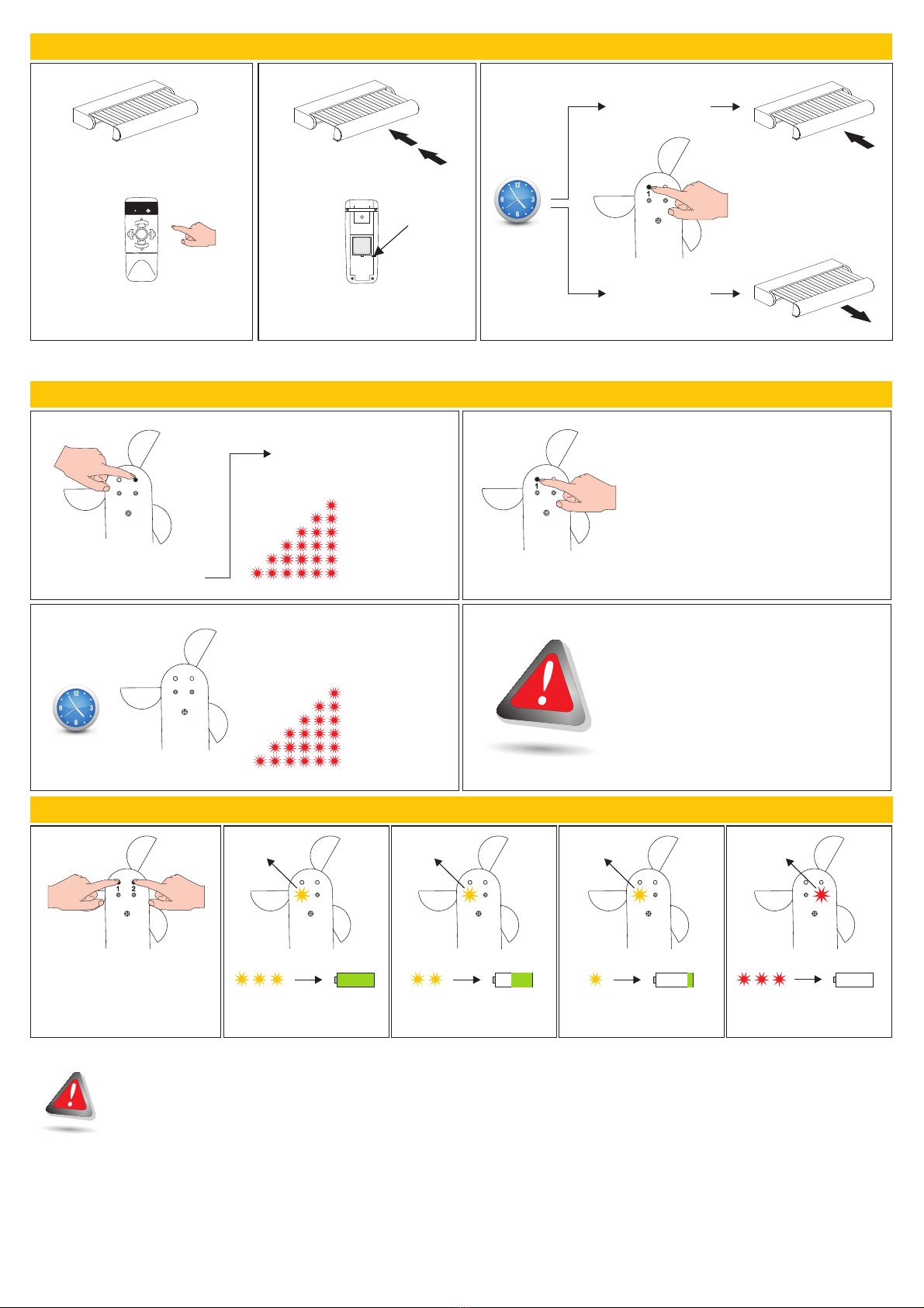
Check that the sensor has been installed on the correct position and well exposed to the wind and that there are no obstacles to the blades rotation.
This sensor has not been studied for working with blades turned upside down (as on the first picture).
02. Check that the package is intact and has not suffered damage in transit.
02. Warnings on safety installation
03. Technical characteristics (related to 20 °C working temperature)
- Power supply:
- Battery duration (estimate) :
- Working temperature :
- Working frequency :
battery
5 years
-20°C / +55°C
433,92 MHz
3V
wind
from to Km/h
- Supported sensors :
- Wind threshold : 5 35
1
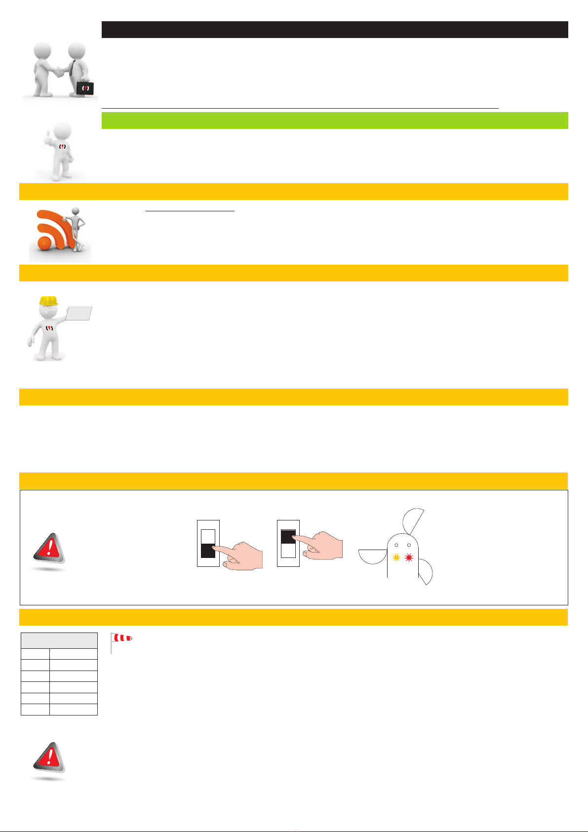
ON
1
ON
SWITCH OFF SWITCH ON
1 2
ONCE THE SWITCH IS « »
THE MISTRAL BATTERY SIGNALS
ITS ACTIVATION THROUGH LEDS LIGHTING.
IF THIS DOES NOT HAPPEN
PUT SWITCH ON THE « »POSITION
WAIT 30 seconds AND REPEAT
THE OPERATION.
ON
OFF
OPEN THE MISTRAL BATTERY COVER
AND SWITCH IT ON THROUGH
THE SWITCH ON THE BATTERY
04. MISTRAL BATTERY switching on.
05. Wind threshold table and visual signals:
6
5
4
3
2
1
20 Km/h
15 Km/h
10 Km/h
35 Km/h
30 Km/h
25 Km/h
Velocità
Soglia
WIND THRESHOLD
factory set up
(*)
(*)
WIND FUNCTION :
MISTRAL BATTERY sends a wind danger transmission to the tuned receiving
modules when the wind speed exceeds the set threshold for longer than 3 seconds. It
exits the wind alarm mode after 8 minutes from the last gust over the set threshold.
During the wind alarm mode all the commands are off.
In order to preserve the duration of the mounted battery, no signals are sent during the normal working. Only when a transmission due to weather changing
is sent (from wind presence to absence) the red led briefly lights.