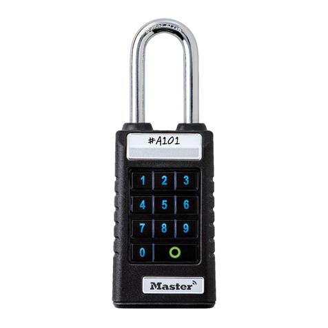
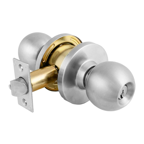
Masterlock ProSeries 6230 User manual

TECHNICAL
MANUAL
ProSeries®Padlock
ISSUE 4.01


1
Master Lock introduced the ProSeries®product line in 1992 with Weather Tough®and High Security,
iron shrouded, rekeyable padlocks. Intent on providing locksmiths with greater ease and flexibility,
Master Lock designed the padlocks to use standard components across the line. Since then, ProSeries®
has grown to include solid body padlocks in Brass, Steel and Aluminum to further satisfy corrosion,
security and safety requirements. Most recently, Master Lock has added extensive interchangeable core
and door hardware cylinder options to create maximum options for padlock integration into facility
padlock and door lock systems. Today, ProSeries®is the only product line available for so many different
applications, making Master Lock the source for complete commercial security.
Table of Contents
ProSeries®Rekeyables Service Procedure 2
ProSeries®6230 Locks Service Procedure 3
ProSeries®6270 Lock Service Procedure 4
ProSeries®Rekeyables Component Parts 5-6
ProSeries®Interchangeable Core Service Procedure 7
ProSeries®Interchangeable Core Component Parts 8
ProSeries®Door Hardware Service Procedure 9
ProSeries®Door Hardware Component Parts 10
Cylinders and Retainers 11-13
Cylinder Service Procedure 14
Keys and Keyways 15
Keying 16
ProSeries®Extensions, Retainers and Drivers 17-18
Tools 19
Bitting Specifications 20
Terminology 21-29

All of the ProSeries®locks have a generic construction technology that
allows for a uniform assembly and disassembly technique. Below is a step-
by-step procedure for disassembling one of these padlocks (refer to
diagram at right for parts and orientation). The only exceptions to this
procedure will be the Door Hardware and IC versions of the lock.
•Use the key to unlock the shackle, A. (If the key is unavailable you will
have to use another method to unlock the shackle).
•Use a 7/64" hexagonal wrench to remove the mounting screw located
inside the toe side shackle hole.
•Holding the trap door, D, in place, lock the shackle, A, into the padlock
body. (This relieves pressure on the extension, E).
•Remove the trap door, D, and the nut, F.
•Remove the cylinder, C.
•Remove the extension, E.
•Remove the locking ball bearings, B, and shackle, A.
The order may be reversed to reassemble the lock. A light application of
assembly grease may be used to hold the ball bearings in place during
assembly.
If the lock only needs to be rekeyed, it is not necessary to remove the
extension, ball bearings, or shackle.
Two functions are available in the locks, NKR (Non Key Retaining) and
NRK (Non Removable Key) and both functions are accomplished as a
design feature of the extension.
The NKR, non key retaining, function extension used in the lock has a
projection on one side. You should note the orientation of this projection
when removing the extension so that you can easily reinstall it during the
reassembly process. Extensions are supplied with different sizes and two
different styles have been used in the ProSeries®locks. Consult the
Extension section, page 17, of this manual for more detailed information.
The NRK, non removable key, function extension does not have a
projection to help with orientation and you will have to rely on the
position of the half-moon shaped actuator the tail of the cylinder contacts.
Again, different sizes and styles are available for use in the ProSeries®
locks, so consult the Extension section, page 17, of this manual for more
detailed information.
See component parts list on page 5.
ProSeries®Rekeyables Service Procedure
2
A
G
B
E
C
D
F

The 6230 is a solid steel body lock using the ProSeries®standard ball
bearing locking mechanism. Disassembling for servicing is similar to the
rekeyables and may be accomplished by following the steps listed below
(refer to diagram at right for parts and orientation).
•Use the key to unlock the shackle, A. (If the key is unavailable you will
have to use another method to unlock the shackle).
•Use a 7/64" hexagonal wrench to remove the mounting screw located
inside the toe side shackle hole.
•Holding the trap door, D, in place, lock the shackle, A, into the padlock
body. (This relieves pressure on the extension.)
•Remove the trap door, D, and the nut, F.
•Remove the cylinder, C.
•Remove the extension, E.
•Remove the locking ball bearings, B, and shackle, A.
The order may be reversed to reassemble the lock. A light application of
assembly grease may be used to hold the ball bearings in place during
assembly.
If the lock only needs to be rekeyed, it is not necessary to remove the
extension, ball bearings, or shackle.
Two functions are available in the locks, NKR (Non Key Retaining) and
NRK (Non Removable Key) and both functions are accomplished as a
design feature of the extension.
The NKR, non key retaining, function extension used in the lock has a
projection on one side. You should note the orientation of this projection
when removing the extension so that you can easily reinstall it during the
reassembly process.
The NRK, non removable key, function extension does not have a
projection to help with orientation and you will have to rely on the
position of the half-moon shaped actuator that the tail of the cylinder
contacts.
See component parts list on page 6.
ProSeries®6230 Locks Service Procedure
3
A
G
B
E
C
D
F

The 6270 is a solid steel body lock. Disassembling for servicing is unique
for this version and may be accomplished by following the steps listed
below (refer to the diagram at the right for parts and orientation).
•Loosen or remove the cylinder mounting screw on the back of the lock
body with a 3/32" socket wrench.
•Use the key to unlock the shackle. (If key is unavailable you will have to
use another method to unlock the shackle).
•Pull on the cylinder to remove it.
•For rekeying, loosen the set screw, (1.5 mm), inside the last pin chamber
to allow 180°rotation of the plug.
•Align pin chambers in plug with service holes in the bottom of the shell
to remove existing bottom pins and replace with new combination.
•Rotate plug to key pull position and tighten the set screw in the last pin
chamber.
•To exchange the cylinder, remove the roll pin at the back of the plug,
remove the shackle and install shackle on a new cylinder.
The order may be reversed to reassemble the lock.
This lock is available with the ProSeries®K6000 or K7000 key.
The 700A keyway is available for keying alike to other brands of locks
which may be found in the field.
See component parts list on page 6.
ProSeries®6270 Locks Service Procedure
4
A
C

Vertical Components
Model # Shackle Shackle Ball Bearings Cylinder Trap Door Extension Flared Nut Screw
Clearance (b) NKR NRK
ABCD E FG
2-1/8" Wide Laminated Steel Body. Shackle Dimensions: a: 5/16" c: 7/8"
6121 1-1/8" 293S6121
6121LF 1-1/2" 293LF6121 See List
6121LJ 2-3/8" 293LJS6121 6121-0427 Page 14 6121-0420 6121-0423 6121-0424 6121-0421 6121-0422
6121LN 5-3/4" 293LNS6121
2-3/8" Wide Laminated Steel Body. Shackle Dimensions: a: 3/8" c: 7/8"
6125 1-3/8" 293S6125
6125LJ 2-3/8" 293LJS6125 6121-0427 See List, P. 14 6121-0420 6121-0423 6121-0424 6121-0421 6121-0422
2-5/8" Wide Laminated Steel Body. Shackle Dimensions: a: 7/16" c: 7/8"
6127 1-3/8" 293S6127
6127LH 1-7/8" 293LHS6127 See List
6127LJ 2-3/8" 293LJS6127 6121-0427 Page 14 6121-0420 6121-0423 6121-0424 6121-0421 6121-0422
6127LN 5-3/4" 293LNS6127
2-1/8" Wide Laminated Steel Body. Shackle Dimensions: a: 5/16" c: 7/8"
6321 3/4" 293S6321 6121-0427 See List, P. 14 6121-0420 6121-0423 6121-0424 6121-0421 6121-0422
2-3/8" Wide Laminated Steel Body. Shackle Dimensions: a: 3/8" c: 7/8"
6325 3/4" 293S6325 6121-0427 See List, P. 14 6121-0420 6121-0423 6121-0424 6121-0421 6121-0422
2-5/8" Wide Laminated Steel Body. Shackle Dimensions: a: 7/16" c: 7/8"
6327 3/4" 293S6327 6121-0427 See List, P. 14 6121-0420 6121-0423 6121-0424 6121-0421 6121-0422
1-9/16" Wide Solid Brass Body. Shackle Dimensions: a: 1/4" c: 25/32"
6830 1-1/16" 293S6830
6830B 1-1/16" 293B6830 See List
6830LF 1-9/16" 293LFS6830 0220-0302 Page 14 6830-0420 6830-0421 6830-0422 6121-0421 6121-0422
6830LT 3" 293LTS6830
1-3/4" Wide Solid Brass Body. Shackle Dimensions: a: 5/16" c: 29/32"
6840 1-3/16" 293S6121
6840B 1-3/16" 293B6840
6840LF 1-9/16" 293LFS6121 See List
6840LJ 2-7/16" 293LJS6121 6121-0427 Page 14 6121-0420 6121-0423 6121-0424 6121-0421 6121-0422
6840BLJ 2-7/16" 293LJB6840
6840LN 5-3/4" 293LNS6121
ProSeries®Rekeyables Component Parts
5
Weather Tough®
Iron ShroudSolid Brass
b
ac
b
ac
b
ac
d dd
ShroudedWeather Tough Brass/Aluminum/Steel

ProSeries®Rekeyables Component Parts
6
Vertical Components
Model # Shackle Shackle Ball Bearings Cylinder Trap Door Extension Flared Nut Screw
Clearance (b) NKR NRK
ABCD E FG
2" Wide Solid Brass Body. Shackle Dimensions: a: 3/8" c: 29/32"
6850 1-1/2" 293S6125
6850B 1-1/2" 293B6850 See List
6850LJ 2-1/2" 293LJS6125 6121-0427 Page 14 6121-0420 6121-0423 6121-0424 6121-0421 6121-0422
6850BLJ 2-1/2" 293LJB6850
1-9/16" Wide High Visibility Aluminum Body. Shackle Dimensions: a: 1/4" c: 25/32"
6835RED 1-1/16" 293S6830
6835LFRED 1-9/16" 293LF6830
6835ORJ 1-1/16" 293S6830
6835LFORJ 1-9/16" 293LFS6830
6835YLW 1-1/16" 293S6830
6835LFYLW 1-9/16" 293LFS6830 0220-0302 See List 6830-0420 6831-0421 6830-0422 6121-0421 6121-0422
6835GRN 1-1/16" 293S6830 Page 14
6835LFGRN 1-9/16" 293LFS6830
6835BLU 1-1/16" 293S6830
6835LFBLU 1-9/16" 293LFS6830
6835BLK 1-1/16" 293S6830
6835LFBLK 1-9/16" 293LFS6830
1-9/16" Wide Solid Steel Body. Shackle Dimensions: a: 1/4" c: 25/32"
7030 1-1/16" 293S6830 See List
7030LF 1-9/16" 293LFS6830 0220-0302 6830-0420 6831-0421 6830-0422 6121-0421 6121-0422
7030LT 3" 293LTS6830 Page 14
1-3/4" Wide Solid Steel Body. Shackle Dimensions: a: 5/16" c: 29/32"
7040 1-3/16" 293S6121 See List
7040LJ 2-1/2" 293LJS6121 6121-0427 Page 14 6121-0420 6841-0421 6121-0424 6121-0421 6121-0422
2" Wide Solid Steel Body. Shackle Dimensions: a: 3/8 c: 29/32"
7050 1-1/2" 293S6125 6121-0427 See List 6121-0420 6841-0421 6121-0424 6121-0421 6121-0422
7050LJ 2-1/2" 293LJS6125 Page 14
2-1/2" Wide Round Solid Steel Body. Shackle Dimensions: A: 7/16" C: 7/8"
6230 1-1/8" 293S6230 230-0302 See List 6121-0420 6121-0425 6121-0426 6121-0421 6121-0422
6230LH 2 293LHS6230 Page 14
6270 N/A N/A N/A 6270-321 N/A N/A N/A N/A NA
1-9/16" Wide Solid Steel Body. Shackle Dimensions: a: 1/4" c: 25/32"
7035 1-1/16" 293S6830 See List, P. 14 6830-0420 6831-0421 6830-0422 6121-0421 6121-0422
1-3/4" Wide Solid Steel Body. Shackle Dimensions: a: 5/16" c: 29/32"
7045 1-3/16" 293S6121 Page 14 6121-0420 6841-0421 6121-0424 6121-0421 6121-0422
Solid AluminumSolid Steel
Shrouded
Solid Steel
Solid Brass
*Note: the 296W6000 cylinder is pinned with only 5 pins, for 6 pins order 296W7000
b b
ac ac
b
ac
b
ac
b
ac
d d
ddd
ShroudedWeather Tough Round SteelBrass/Aluminum/Steel Shrouded Solid Steel

The ProSeries®Interchangeable Core locks employ a construction
technology similar to that used in the Rekeyables. It also allows for a
uniform assembly and disassembly technique. Below is the step by step
procedure for disassembling this version of padlock (refer to diagram at
right for parts and orientation). The only exceptions to this procedure
will be the Rekeyables and Door Hardware versions of the lock.
•Use the control key to remove the IC cylinder, C. (If key is unavailable
you will have to use another method).
•Remove the ring retainer.
•Remove the steel retainer plate.
•Remove the throw member.
•Remove the extension, E.
•Remove the locking ball bearings, B, and shackle, A.
The order may be reversed to reassemble the lock. A light application of
assembly grease may be used to hold the ball bearings in place during
assembly.
If the lock only needs to be rekeyed, it is not necessary to remove the ring
retainer, retainer plate, extension, ball bearings, or shackle.
Two functions are available in the locks, NKR (Non Key Retaining) and
NRK (Non Removable Key) and both functions are accomplished as a
design feature of the extension.
The NKR, non key retaining, function extension used in the lock has a
projection on one side. You should note the orientation of this projection
when removing the extension so that you can easily reinstall it during the
reassembly process. Extensions are supplied with different sizes and
orientations, and two different styles have been used in the ProSeries®
locks. Consult the Extension section, page 17, of this manual for more
detailed information.
The NRK, non removable key, function extension does not have a
projection to help with orientation and you will have to rely on the
position of the half-moon shaped actuator the tail of the cylinder contacts.
Again, different sizes and styles are available for use in the ProSeries®
locks, so consult the Extension section, page 17, of this manual for more
detailed information.
See component parts list on page 8.
ProSeries®Interchangeable Core Service Procedure
7
A
B
E
C

ProSeries®Interchangeable Core Component Parts
8
Weather Tough®
Iron
Shroud
Solid BrassSolid AluminumSolid Steel
Shrouded
Solid Steel
b b
ac ac
b
ac
b
ac
d d
dd
Shrouded Round SteelBrass/Aluminum/Steel Shrouded Solid Steel
Vertical Components
Model # Shackle Shackle Ball Bearings Cylinder Trap Door Extension Flared Nut Screw
Clearance (b) NKR NRK
ABCD E FG
2-1/8" Wide Laminated Steel Body. Shackle Dimensions: a: 5/16" c: 7/8"
6421 1-1/8" 293S6121
6421LF 1-1/2" 293LF6121 6121-0427 See List P.13 N/A 6121-0423 6121-0424 N/A N/A
6421LJ 2-3/8" 293LJS6121
6421LN 5-3/4" 293LN6121
2-5/8" Wide Laminated Steel Body. Shackle Dimensions: a: 7/16" c: 7/8"
6427 1-3/8" 293S6127
6427LH 1-7/8" 293LHS6127
6427LJ 2-3/8" 293LJ6127 6121-0427 See List P.13 N/A 6121-0423 6121-0424 N/A N/A
6427LN 5-3/4" 293LN6127
2-1/8" Wide Laminated Steel Body. Shackle Dimensions: a: 5/16" c: 7/8"
6521 3/4" 293S6321 6121-0427 See List P.13 N/A 6121-0423 6121-0424 N/A N/A
2-5/8" Wide Laminated Steel Body. Shackle Dimensions: a: 7/16" c: 7/8"
6527 3/4" 293S6327 6121-0427 See List P.13 N/A 6121-0423 6121-0424 N/A N/A
1-9/16" Wide Solid Brass Body. Shackle Dimensions: a: 1/4" c: 25/32"
6831 1-1/16" 293S6830
6831B 1-1/16" 293B6830 0220-0302 See List P.13 N/A 6830-0421 6830-0422 N/A N/A
6831LF 1-9/16" 293LFS6830
6831BLF 1-9/16" 293LFB6830
1-3/4" Wide Solid Brass Body. Shackle Dimensions: a: 5/16" c: 29/32"
6841 1-3/16" 293S6121
6841B 1-3/16" 293B6840
6841LF 1-1/2" 293LFS6121 6121-0427 See List P.13 N/A 6841-0421 6121-0424 N/A N/A
6841LJ 2-7/16" 293LJS6121
6841BLJ 2-7/16" 293LJB6840
2" Wide Solid Brass Body. Shackle Dimensions: a: 3/8" c: 29/32"
6851 1-1/2" 293S6125
6851B 1-1/2" 293B6850 6121-0427 See List P.13 N/A 6841-0421 6121-0424 N/A N/A
6851LJ 2-1/2" 293LJ6125
6851BLJ 2-1/2" 293LJB6850
1-9/16" Wide High Visibility Aluminum Body. Shackle Dimensions: a: 1/4" c: 25/32"
6836RED 1-1/16" 293S6830
6836LFRED 1-9/16" 293LFS6830
6836LTRED 3" 293LTS6830
6836ORJ 1-1/16" 293S6830
6836LFORJ 1-9/16" 293LFS6830
6836LTORJ 3" 293LTS6830
6836YLW 1-1/16" 293S6830
6836LFYLW 1-9/16" 293LFS6830
6836LTYLW 3" 293LTS6830 0220-0302 See List P.13 N/A 6831-0421 6830-0422 N/A N/A
6836GRN 1-1/16" 293S6830
6836LFGRN 1-9/16" 293LFS6830
6836LTGRN 3" 293LTS6830
6836BLU 1-1/16" 293S6830
6836LFBLU 1-9/16" 293LFS6830
6836LTBLU 3" 293LTS6830
6836BLK 1-1/16" 293S6830
6836LFBLK 1-9/16" 293LFS6830
6836LTBLK 3" 293LTS6830
1-9/16" Wide Solid Steel Body. Shackle Dimensions: a: 1/4" c: 25/32"
7031 1-1/16" 293S6830
7031LF 1-9/16" 293LFS6830 0220-0302 See List P.13 N/A 6831-0421 6830-0422 N/A N/A
7031LT 3" 293LTS6830
1-3/4" Wide Solid Steel Body. Shackle Dimensions: a: 5/16" c: 29/32"
7041 1-3/16" 293S6121
7041LJ 2-1/2" 293LJS6121 6121-0427 See List P.13 N/A 6841-0421 6121-0424 N/A N/A
2" Wide Solid Steel Body. Shackle Dimensions: a: 3/8" c: 29/32"
7051 1-1/2" 293S6125 6121-0427 See List P.13 N/A 6841-0421 6121-0424 N/A N/A
7051LJ 2-1/2" 293LJS6125
1-9/16" Wide Solid Steel Body. Shackle Dimensions: a: 1/4" c: 25/32"
7036 1-1/16" 293S6830 0220-0302 See List P. 13 N/A 6831-0421 6830-0422 N/A N/A
1-3/4" Wide Solid Steel Body. Shackle Dimensions: a: 5/16" c: 29/32"
7046 1-3/16" 293S6121 6121-0427 See List P. 13 N/A 6841-0421 6121-0424 N/A N/A

The ProSeries®Door Hardware locks employ a construction technology
similar to that used in the Rekeyables. It also allows for a uniform
assembly and disassembly technique. Below is the step by step procedure
for disassembling this version of padlock. The only exception to this
procedure will be the IC version of the lock.
•Use the key to unlock the shackle, A. (If key is unavailable you will have
to use another method to unlock the shackle).
•Use a 7/64" hexagonal wrench to remove the mounting screw located
inside the toe side shackle hole.
•Holding the plug retainer, D, in place, lock the shackle, A, into the
padlock body. (This relieves pressure on the extension.)
•Remove the cylinder adapter with the cylinder, C.
•Remove the driver if it did not come out with the cylinder adapter and
the cylinder.
•Remove the extension, E.
•Remove the locking ball bearings, B, and shackle, A.
The order may be reversed to reassemble the lock. A light application of
assembly grease may be used to hold the ball bearings in place during
assembly.
If the lock only needs to be rekeyed, it is not necessary to remove the
extension, ball bearings, or shackle.
Two functions are available in the locks, NKR (Non Key Retaining) and
NRK (Non Removable Key) and both functions are accomplished as a
design feature of the extension.
The NKR, non key retaining, function extension used in the lock has a
projection on one side. You should note the orientation of this projection
when removing the extension so that you can easily reinstall it during the
reassembly process. Extensions are supplied with different sizes and two
different styles have been used in the ProSeries®locks. Consult the
Extension section, page 17, of this manual for more detailed information.
The NRK non removable key, function extension does not have a
projection to help with orientation and you will have to rely on the
position of the half-moon shaped actuator the tail of the cylinder contacts.
Again, different sizes and styles are available for use in the ProSeries®
locks, so consult the Extension section, page 17, of this manual for more
detailed information.
See component parts list on page 10.
ProSeries®Door Hardware Service Procedure
9
A
G
B
E
C
D

ProSeries®Door Hardware Component Parts
10
Vertical Components
Model # Shackle Shackle Ball Bearings Cylinder Retainer Extension Flared Nut Screw
Clearance (b) NKR NRK
ABCD E FG
2-1/8" Wide Laminated Steel Body. Shackle Dimensions: a: 5/16" c: 7/8"
6621 1-1/8" 293S6121
6621LF 1-1/2" 293LF6121
6621LJ 2-3/8" 293LJS6121 6121-0427 See List P.12 298-0629 6121-0423 6121-0424 N/A 6621-0450
6621LN 5-3/4" 293LN6121
2-5/8" Wide Laminated Steel Body. Shackle Dimensions: a: 7/16" c: 7/8"
6627 1-3/8" 293S6127
6627LH 1-7/8" 293LHS6127
6627LJ 2-3/8" 293LJ6127 6121-0427 See List P.12 298-0629 6121-0423 6121-0424 N/A 6621-0450
6627LN 5-3/4" 293LN6127
2-1/8" Wide Laminated Steel Body. Shackle Dimensions: a: 5/16" c: 7/8"
6721 3/4" 293S6321 6121-0427 See List P.12 298-0629 6121-0423 6121-0424 N/A 6621-0450
2-5/8" Wide Laminated Steel Body. Shackle Dimensions: a: 7/16" c: 7/8"
6727 3/4" 293S6327 6121-0427 See List P.12 298-0629 6121-0423 6121-0424 N/A 6621-0450
1-3/4" Wide Solid Brass Body. Shackle Dimensions: a: 5/16" c: 29/32"
6842 1-3/16" 293S6121
6824B 1-3/16" 293B6840
6842LF 1-1/2" 293LFS6121 6121-0427 See List P.12 298-0629 6121-0423 6121-0424 N/A 6621-0450
6842LJ 2-1/2" 293LJS6121
6842BLJ 2-1/2" 293LJB6840
2" Wide Solid Brass Body. Shackle Dimensions: a: 3/8" c: 29/32"
6852 1-1/2" 293S6125
6852B 1-1/2" 293B6850 6121-0427 See List P.12 298-0629 6121-0423 6121-0424 N/A 6621-0450
6852LJ 2-1/2" 293LJS6125
6852BLJ 2-1/2" 293LJB6850
1-3/4" Wide Solid Steel Body. Shackle Dimensions: a: 5/16" c: 29/32"
7042 1-3/16" 293S6121
7042LJ 2-1/2" 293LJS6121 6121-0427 See List P.12 298-0629 6121-0423 6121-0424 N/A 6621-0450
2" Wide Solid Steel Body. Shackle Dimensions: a: 3/8" c: 29/32"
7052 1-1/2" 293S6125 6121-0427 See List P.12 298-0629 6121-0423 6121-0424 N/A 6621-0450
7052LJ 2-1/2" 293LJ6125
1-3/4" Wide Solid Steel Body. Shackle Dimensions: a: 5/16" c: 29/32"
7047 1-3/16" 293S6121 6121-0427 See List. P.12 298-0629 6121-0423 6121-0424 N/A 6621-0450
Weather Tough®
Iron
Shroud
Solid BrassSolid Steel
Shrouded
Solid Steel
b
ac
d
Shrouded Solid Steel
b
ac
b
ac
b
ac
d dd
ShroudedWeather Tough Brass/Aluminum/Steel

Master Lock Company makes seven basic cylinder sizes/types for use in our padlocks;
1. A small diameter cylinder for some of our laminated locks.
2. A four pin cylinder for our laminated locks.
3. A five pin cylinder for our laminated rekeyable locks
4. A six pin cylinder for our ProSeries®locks.
1. The small diameter cylinder is generally referred to as the number W7
cylinder and is used in various products where the available space is
limited. This cylinder is used in the number 7 laminated padlock, the
gun lock, etc., and is generally not accessible for rekeying. In those
cases where it can be rekeyed, it uses the same pins used in the first four
classes above. Those pins are available in our #291 pinning kit found
on page 19. See page 14 for service procedures.
2. The four pin cylinder is generally referred to as the number W1
cylinder and is used in the number 1, 3, 5 laminated padlocks, and
many other products. In many cases it is not accessible for rekeying,
but when it can be rekeyed you may use our #291 pinning kit.
Servicing procedures may be found on page 14.
3. The five pin cylinder is generally known as our number W27 cylinder
and is found in our laminated rekeyable locks such as the number 21,
24, 25, and 27. It may be rekeyed using our #291 pinning kit shown
on page 19.
There are times when you may want to use a four pin cylinder in a lock
designed for the five pin cylinder because of keyway compatibility.
That can be accomplished by using the 27-0334 plug extension which
adapts the four pin cylinder to the five pin length.
4. The six pin cylinder is referred to by two different part numbers,
depending on the number of pin chambers that are pinned. When
pinned with only five pins, it is called the W6000 and if all six pins are
used it is called the W7000. This cylinder is found in our ProSeries®
products and may also be rekeyed using our #291 pinning kit.
Effective mid-2001, Master Lock Company will implement a new six
pin cylinder and key. The cylinder will change from a crimp to an
E-clip which reflects tighter tolerances between the plug and shell. The
new key has a radiused blade bottom. This running change should have
no effect on key operation from old to new cylinder types.
You can use two of the 27-0334 plug adapters to install a four pin
cylinder where a six pin one would normally be required. It isn't
possible to install a five pin cylinder where a six pin is required. See
page 14 for keyways and part numbers.
Cylinders and Retainers
11
5. A cylinder for our number 19 lock.
6. Cylinders compatible with various door hardware locks
made by others.
7. SFIC cylinders.

5. The W19 cylinder is only used in the number 19 lock and it is not
really accessible for rekeying without drilling the rivets. This cylinder
uses .125" diameter pins and a .025" increment. The shell is crimped
on both sides and does not allow the service technique typical on the
old style W1 cylinder. The only option available for rekeying would be
to use the holes on the bottom of the shell to remove pins from the
plug and replace them with new ones.
6. The door hardware cylinders are rekeyable using standard .115"
diameter pins. The plug is mounted to the shell with a ring retainer,
and use of a follower is recommended for rekeying. In order to mount
the cylinders in the lock, a cylinder retainer plug is placed over the bible
of the cylinder. The retainer plug has a threaded hole used to mount it
to the lock via the toe side shackle hole and the socket screw. This
cylinder also requires a special driver to be placed between the cylinder
tail and the lock extension in order to function. The listing below
allows construction of a correct cylinder part number when ordering
from Master Lock.
Cylinders and Retainers continued
12
D045KD
Door Hardware Cylinder Keying Specification
KD –Keyed Different
Keyway KA –Keyed Alike
KZ –Zero Bitted
KDMK –KD Master Keyed
KAMK –KA Masker keyed
Manufacturer’s Brand Name
Arrow 10
Corbin 59A1-2 01
Corbin 60 29
Corbin Russwin L4 07
Falcon 1573, 1577* 14
Harloc SE-1* 02
Kwikset* 12
Lockwood 08
Lori L200* 02
Lori Locksmith 80 80
Loricentric 90 90
Master/Dexter 67* 32
Russwin 981/852 11
Russwin D1 30
Sargent LA-LC* 36
Sargent RA-RC* 70
Sargent S* 02
Sargent U* 02
Schlage C 04
Schlage E 34
Segal 9.265 27
Weiser* 13
Weslock 33
Yale 8 03
Yale GA 15
Number of pins
5 –five
6 –six
* indicates a composite keyway

7. The Interchangeable Core cylinders are constructed to the SFIC
standards that you encounter with many other brands. Keying uses the
same techniques employed for those cylinders.
Master Lock offers IC cylinders keyed to existing key systems if you are
able to supply the combinations for the operating key, the TMK, and
the Control key. Master Lock also has the ability to recreate your entire
key system, including all potential expansion, if you can supply bitting
combinations of all keys that have been used.
At present, Master Lock offers IC cylinders compatible with the A2 and A4 format from the factory. If you are equipped for
pinning SFIC cylinders, you can key the cylinders into an existing A3 system without difficulty. The listing below allows
construction of a correct IC cylinder part number when ordering from Master Lock.
Cylinders and Retainers continued
13
CA604KD
Interchangeable Core Keying Specification
Keyway/Key Section KD –Keyed Different
KA –Keyed Alike
UN –Uncombinated
KDMK –KD Master Keyed
KAMK –KA Master keyed
Finish
04 –Satin Brass
26D –Satin Chrome
Number of pins
6 –six
7 –seven
Manufacturer’s Brand Name
A–Best A Keyway
B–Best B Keyway
C–Best C Keyway
D–Best D Keyway
E–Best E Keyway
F–Best F Keyway
G–Best G Keyway
H–Best H Keyway
J–Best J Keyway
K–Best K Keyway
L–Best L Keyway
M–Best M Keyway
Q–Best Q Keyway
W–Arrow 1C Keyway
X–Arrow 1D Keyway
Y–Master Lock Keyway

All ProSeries®locks are supplied with a six pin length cylinder for uniform keying capability. The ProSeries®cylinder may be
combinated with 4, 5, or 6 pins to accommodate existing key codes.
CYLINDER
Pin chambers in this cylinder are drilled from the shell into the bible.
Care should be exercised to avoid turning the plug 180°because, at that
point, the bottom pins will align with the service holes on the bottom of
the shell and could be lost.
1. The plug is held in the shell via a crimp in the end of the shell.
This crimp prevents removal of the plug from the shell unless you have
a Master Lock plug follower with a flat on it.
2. The bottom of the plug is undercut at the keyway to allow it to bypass
the crimp. The Master Lock plug follower is designed to fit the end of
the plug and automatically align with the crimp in the shell.
3. To remove the plug, turn it 90°counterclockwise and, with the special
plug follower, push the plug from the shell.
Once you have changed the pinning combination, insert the plug into
the shell.
Effective mid-2001, the crimp retainer is replaced with a new design
E-clip. To service the new cylinder type, remove the E-clip and then
follow step 3 above. This running change replacement will eliminate
the crimped retainer for the plug in all ProSeries®6000 and 7000
keyway cylinders. This new design cylinder will also be supplied with a
new key design. The new keys will have radiused blade bottoms and the
section stamping will include a suffix “B”for ease of identification
(see page 15).
Cylinder Service Procedure
14
Crimp
E-Clip
Rekeyable Cylinders
Part Number by Cylinder Length
No. of Pins Keyway 4 Pin 5 Pin 6 Pin Keying
4 K1 295W1* 295W1* 296W1 KD
5 K15 N/A 295W15 296W15 KD
5 K17 N/A 295W17 296W17 KD
5 K27 N/A 295W27 296W27 KD
5 K81 N/A 295W81 296W81 KD
5 K600A N/A 295W600 296W600A KD
6 K700A N/A N/A 296W700A KD
5 K6000 N/A 295W6000 296W6000 KD
6 K7000 N/A N/A 296W7000 KD
* Includes plug extension for 4 pin cylinder
NOTE: For KA or MK'd, insert that specification in front of the ‘W’ in the above part number.
For Zero Bitted, use suffix ‘KZ’ with above part number

Master Lock uses a wide range of keys and keyways. Below illustrates the relationship of keys to keyways and the corresponding
part numbers.
Four Pin Five Pin
Five Pin
Five Pin Six Pin
Keys and Keyways
15
900
K900
W900
SAFETY
LOCKOUT
K400
W400
K7000
W7000
K1
W1
K1R
W1R
K2
W2
K15
W15
K17
W17
K27
W27
K81
W81
K81MK
W81MK
K81R
W81R
K6000
W6000
6000B
K6000
W6000
7000B
K7000
W7000

Master Lock keys are coded from bow to tip and with a few exceptions, the increment used
is .0155". Master Lock keys will be encountered with two types of stamping on them.
Both direct and blind codes are stamped on the keys for different products. In the 291 pin
kit you will find the 290-0371 slip gauge for decoding keys. For ProSeries®products,
use the top slot in the gauge. Insert the key in the slot at the large end perpendicular to
the gauge. Once inserted, pull the key toward the smaller end of the slot until it stops.
The number stamped on the gauge directly below where the key stops is the cut depth for
that cut position on the key. Repeat the process for each cut position on the key to
determine the actual combination of the key.
The cylinder being rekeyed may be set to an existing key combination or it may be zero-bitted. In either case, follow the plug
out of the shell and discard the existing pins from the plug. If the cylinder was Master Keyed, also remove any master pins that
may have been retained in the shell. For the combination decoded, select the appropriate length pin from the 291 pinning kit,
and install in the appropriate pin chamber of the plug. Once all pins have been installed, insert the plug into the shell and
check for smoothness of operation. If you note roughness in the operation, check the key to be sure it has been produced to the
bitting specifications on page 20.
MASTER KEYING
Most keying system software offers the option of providing a pinning
chart. It is advisable to use that option. If the option is not available,
the following example illustrates the procedure required to determine
the pinning of a master keyed cylinder.
With the example master key combination of 047345 at right, and the
change key combination of 405253, the first step is to figure out the
bottom pins that you must install in the cylinder, then the required master
pins must be determined.
Bottom pins must be selected to allow operation of the shallowest cut
per position in the cylinder for either key. By comparing the two
combinations, select the shallowest cut for each cut position from either
key. In our example we have highlighted the shallowest cut depth,
and you can see that our bottom pins for the cylinder will be 005243.
The master pin sizes are determined by subtracting the shallowest cut
depth from the deepest cut depth for each pin position in the lock.
As noted in the example, the difference is 442112.
From this process, we know that in the first pin chamber we must have
a number zero bottom pin and a number 4 master pin for both keys
to operate. The illustration at the right shows the pinning for the master
keyed cylinder example. Depending upon the size of your key system,
you may or may not require master pinning in all of the pin chambers.
If you find that some cylinders require master pins in different pin
chambers or if different cylinders require different quantities of pin
chambers to have master pins, question the design of the system before
proceeding. Having master pins in different pin chambers may indicate
that the system utilizes a Rotating Constant Method of progression, which
should be verified. Having different quantities of master pins in different
cylinders usually indicates faulty key system design, and you should
recommend that the system be replaced.
Keying
16
047345
405253
Bottom Pins are bold.
047345
405253
442112
Difference equals master pins

EXTENSIONS
As noted in the exploded views, all ProSeries®locks use an extension
mechanism that causes the ball bearings to lock or unlock the shackle.
Typically, ProSeries®locks are supplied with a non key retaining function
extension. There are five different variations of this extension you may
encounter as shown here.
The 2 right extensions are the original position used in the Weather
Tough®, Shrouded, Solid Body Aluminum, and Solid Body Brass locks.
The 2 left extensions are the version used in all Solid Body Steel locks.
The middle extension is used in the 6230.
The differences are in size and/or the location of the projection on the
spring washer. Its position is critical to operation of the lock. The two
positions you will encounter for that projection are shown at the right.
There are three different extensions used for the NRK, (Non Removable
Key), function and they are shown at the right. Care should be taken
to position them correctly within the lock during assembly. Consult the
component parts listings in this manual to determine the actual part
numbers for the extensions.
RETAINERS
There are three different types of retainers used in ProSeries®locks.
A ring retainer can be found in the IC lock. It is a standard size and is
used to position a retainer plate for the throw member. In the door
hardware locks, a Retainer Plug (PN. 298-0629) is used to position the
door hardware cylinder. A trap door, screw, and nut (not pictured)
are used to position the cylinder in the other version locks, see the
component parts listings for specific part numbers of particular locks.
DRIVERS
The door hardware locks require a driver to allow the door hardware
cylinder to drive the extension. There are four driver types available and
they are shown on the right. Shown is the distinctive feature of the driver
that engages the cylinder.
Positioning the driver on the cylinder should always be done to ensure
that the orientation of the driver forms the assembly profile at the right.
ProSeries®Extensions, Retainers and Drivers
17

The Lori cylinders are available from Master Lock as part of the lock assembly and will be supplied with the 298-0626 driver.
If you are using a Medeco 20-20000 or 20W20000 cylinder you should use a number 298-0627 driver. For all Schlage cylinders
and the ASSA 65611 cylinder you can use a 298-0628 driver. The number 298-0625 driver is used to adapt an Australian
Lockwood cylinder.
Medeco also offers a cylinder that can be used without a driver. Use a 51-0600 or a 51W0600 cylinder for that option,
but realize that it will not be adaptable to a door hardware lockset.
ProSeries®Extensions, Retainers and Drivers continued
18
®
®
®
Lori
Cylinder
Driver
298-0626
Lori
Cylinder
Lori
Key
Cylinder
Retainer
Plug
296-0629
Medeco
Cylinder
Driver
298-0627
Medeco
Cylinder
Medeco
Key
Cylinder
Retainer
Plug
296-0629
Lockwood
Australia
Cylinder
Driver
298-0625
Lockwood
Australia
Cylinder
Lockwood
Australia
Key
Cylinder
Retainer
Plug
296-0629
Schlage
Cylinder
Driver
298-0628
Schlage
Cylinder
Schlage
Key
Cylinder
Retainer
Plug
296-0629
This manual suits for next models
123
Table of contents
Other Masterlock Door Lock manuals
Popular Door Lock manuals by other brands

BURG-WACHTER
BURG-WACHTER TSE PRIME SET 5021 PINCODE Assembly and user's manual

Allegion
Allegion LOCKNETICS NC450 Series installation instructions

LOCKLY GUARD
LOCKLY GUARD DEADBOLT 728Z user manual

LockNet
LockNet Sur-Lock 2000EE installation instructions

Weiser
Weiser Safelock Series instructions

Allegion
Allegion Milre MI-480S user manual