manuals.online logo
Brands
  1. Home
  2. •
  3. Brands
  4. •
  5. Masterlock
  6. •
  7. Door Lock
  8. •
  9. Masterlock BCCO0615 Guide

Masterlock BCCO0615 Guide

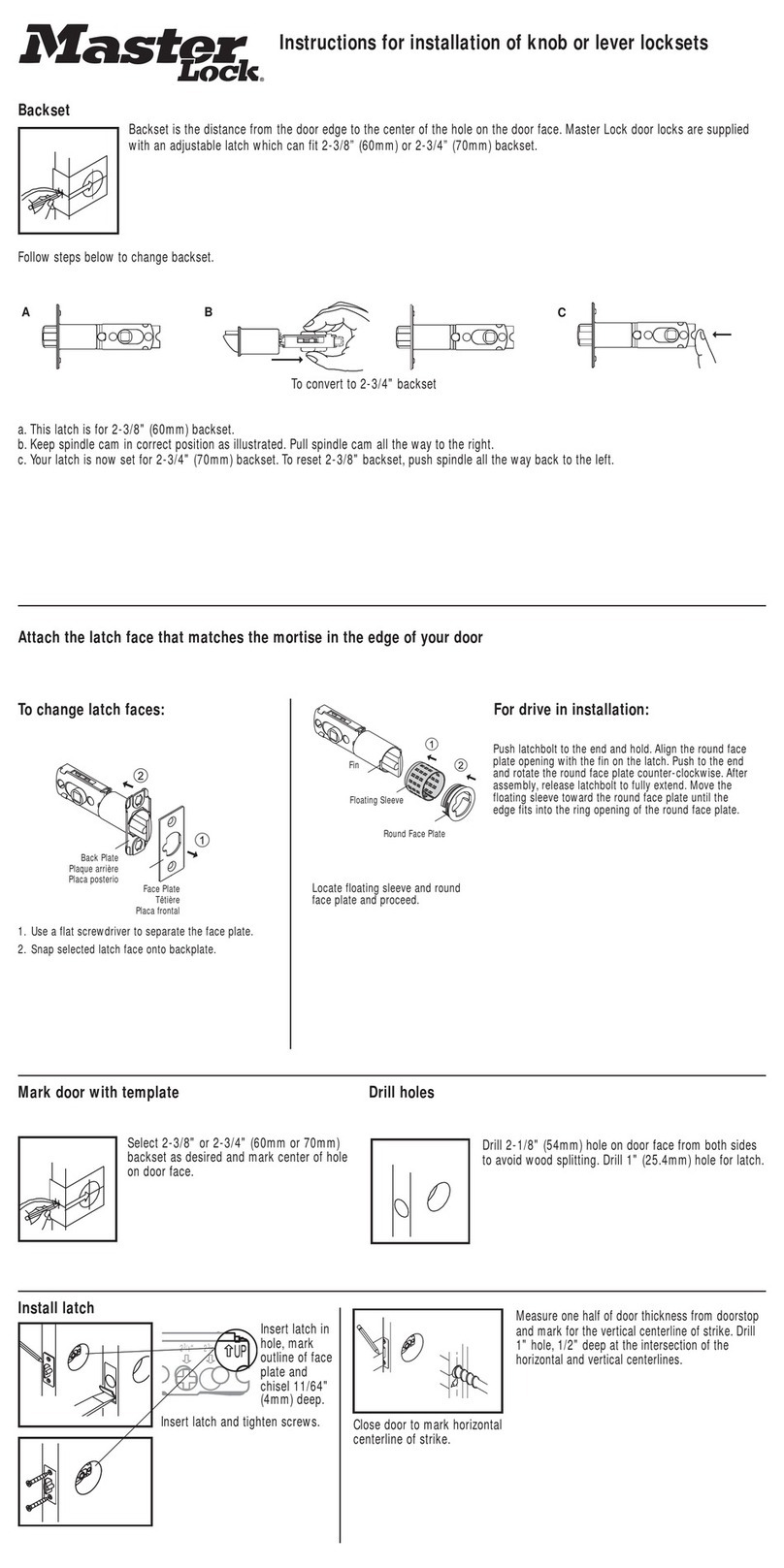
Instructions for installation of knob or lever locksets
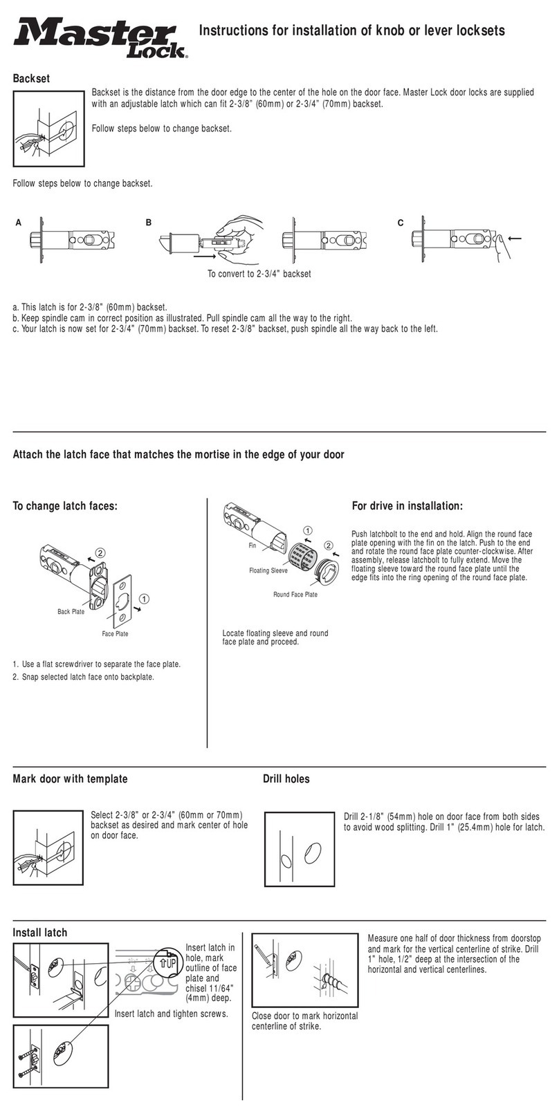
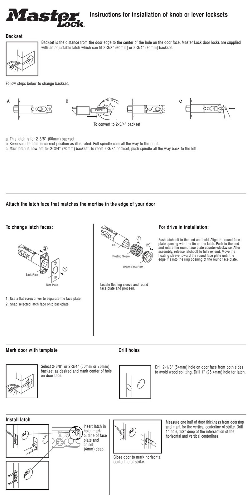
Backset is the distance from the door edge to the center of the hole on the door face. Master Lock door locks are supplied
with an adjustable latch which can fit 2-3/8” (60mm) or 2-3/4” (70mm) backset.
Follow steps below to change backset.
To convert to 2-3/4" backset
Backset
a. This latch is for 2-3/8" (60mm) backset.
b.Keep spindle cam in correct position as illustrated. Pull spindle cam all the way to the right.
c. Your latch is now set for 2-3/4" (70mm) backset.To reset 2-3/8" backset,push spindle all the way back to the left.
AC
B
Mark door with template Drill holes
Measure one half of door thickness from doorstop
and mark for the vertical centerline of strike. Drill
1" hole, 1/2" deep at the intersection of the
horizontal and vertical centerlines.
Close door to mark horizontal
centerline of strike.
Insert latch in
hole, mark
outline of face
plate and
chisel 11/64"
(4mm) deep.
Insert latch and tighten screws.
Select 2-3/8" or 2-3/4" (60mm or 70mm)
backset as desired and mark center of hole
on door face.
Drill 2-1/8" (54mm) hole on door face from both sides
to avoid wood splitting. Drill 1" (25.4mm) hole for latch.
Install latch
2
3
/
8
"2
3
/
4
"
UP
Attach the latch face that matches the mortise in the edge of your door
Fin
Floating Sleeve
Round Face Plate
Locate floating sleeve and round
face plate and proceed.
To change latch faces:
1. Use a flat screwdriver to separate the face plate.
2. Snap selected latch face onto backplate.
For drive in installation:
Push latchbolt to the end and hold. Align the round face
plate opening with the fin on the latch. Push to the end
and rotate the round face plate counter-clockwise. After
assembly, release latchbolt to fully extend. Move the
floating sleeve toward the round face plate until the
edge fits into the ring opening of the round face plate.
Back Plate
Face Plate
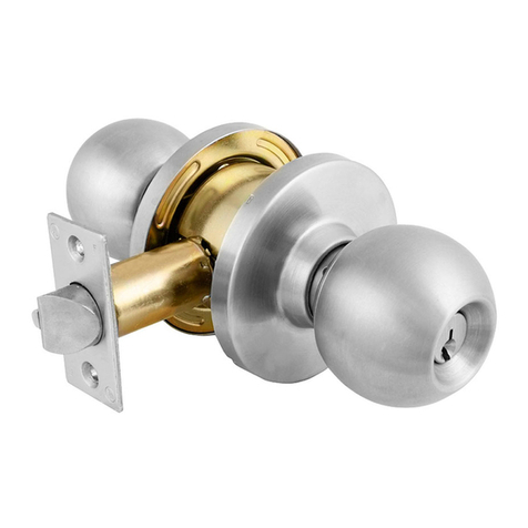
Install outside knob (or lever)
Insert spindle through latch. Press flush against door. (NOTE: Key hole must be in down position).
Install inside knob (or lever)
Install inside knob (or lever) and tighten screws until lock is firm.
B
a. Match screw holes on strike with vertical centerlines on jamb. Mark outline of strike plate and chisel out until strike
is flush with jamb. (Approx. 1/8")
b.Install strike and tighten screws.
Install strike
A
1-3/4"
45mm 1-9/16"
40mm 1-3/8"
35mm
Make 1" Hole at Center of Door Edge
TEMPLATE
Fold on Dotted Line and Fit on Door Edge
For Backset 2-3/8"
For Backset 2-3/4"
23/8"23/4"
UP
2
3
/
8
"2
3
/
4
"
UP
23/8"23/4"
UP
2
3
/
8
"2
3
/
4
"
UP
Instructions for installation of single and
double cylinder deadbolts
Backset is the distance from the door edge to the center of the hole on the door face. Master Lock door locks are supplied
with an adjustable latch which can fit 2-3/8” (60mm) or 2-3/4” (70mm) backset.
Backset
a. Rotate latch crank to retract the latchbolt to the unlock position.
b.Push the change lever up against the top. Hold torque plate and torque spring then pull the extension
plate all the way out. Be sure the 2-3/4" (70mm) screw hole is properly aligned and "change lever"
jumps down to original position.
b.
c. Your latch is now set for 2-3/4" (70mm) backset.
d.Latch may be adjusted back to 2-3/8" (60mm) backset by retracting the latchbolt, pushing up the
"change lever" and moving the extension plate back to its original position.
(NOTE: Be sure the 2-3/8" (60mm) screw hole is properly aligned and "change lever" jumps down to
original position after alignment.
A
B
C
D
1-3/4"
45mm 1-9/16"
40mm 1-3/8"
35mm
Make 1" Hole at Center of Door Edge
TEMPLATE
Fold on Dotted Line and Fit on Door Edge
For Backset 2-3/8"
For Backset 2-3/4"
Mark door with template Drill holes
Measure one half of door thickness from doorstop
and mark for the vertical centerline of strike. Drill
1" hole, 1/2" deep at the intersection of the
horizontal and vertical centerlines.
Close door to mark horizontal
centerline of strike.
Insert latch in
hole, mark
outline of face
plate and
chisel 11/64"
(4mm) deep.
Insert latch and tighten screws.
Select 2-3/8" or 2-3/4" (60mm or 70mm)
backset as desired and mark center of hole
on door face.
Drill 2-1/8" (54mm) hole on door face from both sides
to avoid wood splitting. Drill 1" (25.4mm) hole for latch.
Install latch
2
3
/
8
"2
3
/
4
"
UP
1. Use a flat screwdriver to separate the faceplate.
2. Snap selected faceplate onto backplate.
Attach the faceplate that matches the mortise in the edge of your door
To change faceplates:
Install exterior mechanism – single cylinder
Press cylinder side flush against door making certain the torque blade is properly positioned in latch crank. Tapped holes in
housing of exterior cylinder should be lined up with screwholes.
Key hole should be in down position. TORQUE BLADE SHOULD HORIZONTALLY INSERTED INTO LATCH CRANK.
Install interior mechanism – single cylinder
a. Slide turnpiece and interior rosette onto torque blade.
b.Insert machine screws through holes engaging holes in cylinder and tighten firmly.
Install exterior cylinder – double cylinder
Press exterior cylinder flush against door. Exterior torque blade should be horizontally inserted into latch crank first.
B
Install interior cylinder – double cylinder
a. Press interior assembly flush against door, making certain the torque blade is properly positioned in latch crank.
Keyhole should be in down position.
b.The interior torque blade is inserted into the exterior hole.
c. Insert two screws through countersunk holes engaging holes in exterior cylinder and tighten firmly.
A B
A
C
B
a. Match screw holes on strike with vertical centerlines on jamb. Mark outline of strike plate and chisel out until strike
is flush with jamb. (Approx. 1/8")
b.Install strike and tighten screws.
Install strike
A
Check out the collection of home doors & windows we offer.

This manual suits for next models

2

Other Masterlock Door Lock manuals

Masterlock BAO0315 Guide

Masterlock

Masterlock BAO0315 Guide

Masterlock BAO0115 Guide

Masterlock

Masterlock BAO0115 Guide

Masterlock 6400 User manual

Masterlock

Masterlock 6400 User manual

Masterlock 3681 User manual

Masterlock

Masterlock 3681 User manual

Masterlock dialSpeed 1500eD User manual

Masterlock

Masterlock dialSpeed 1500eD User manual

Masterlock BLC0932DKA4 Guide

Masterlock

Masterlock BLC0932DKA4 Guide

Masterlock ProSeries 6230 User manual

Masterlock

Masterlock ProSeries 6230 User manual

Masterlock BAO0415 Guide

Masterlock

Masterlock BAO0415 Guide

Popular Door Lock manuals by other brands

RIB BLOCK Wi-Fi quick start guide

RIB

RIB BLOCK Wi-Fi quick start guide

Command access LPM110 installation instructions

Command access

Command access LPM110 installation instructions

Aqara U100 user manual

Aqara

Aqara U100 user manual

Allegion 1413.KE Operation

Allegion

Allegion 1413.KE Operation

Allegion SimonsVoss PegaSys 2.1 quick guide

Allegion

Allegion SimonsVoss PegaSys 2.1 quick guide

Nexxt Solutions NHS-D100 quick start guide

Nexxt Solutions

Nexxt Solutions NHS-D100 quick start guide

Emtek Keypad Deadbolt Locksets Installation & programming guide

Emtek

Emtek Keypad Deadbolt Locksets Installation & programming guide

SEVENOC IDL Q1 Setting menu

SEVENOC

SEVENOC IDL Q1 Setting menu

ZKTeco GL300 user manual

ZKTeco

ZKTeco GL300 user manual

VON MORRIS 9001 installation instructions

VON MORRIS

VON MORRIS 9001 installation instructions

Arregui CI10-AL Assembly instructions

Arregui

Arregui CI10-AL Assembly instructions

Schlage M400 Series installation instructions

Schlage

Schlage M400 Series installation instructions

Assa Abloy CLIQ Bluetooth Pairing Guide

Assa Abloy

Assa Abloy CLIQ Bluetooth Pairing Guide

Ingersoll-Rand Schlage ND Series Install Sheet

Ingersoll-Rand

Ingersoll-Rand Schlage ND Series Install Sheet

M-LOCKS E-Pass EP1750 Series Mounting instructions

M-LOCKS

M-LOCKS E-Pass EP1750 Series Mounting instructions

Digi 6600-88 user manual

Digi

Digi 6600-88 user manual

Index FGR-ST-DL210A user manual

Index

Index FGR-ST-DL210A user manual

Häfele EL10K Installation guide & user manual

Häfele

Häfele EL10K Installation guide & user manual

manuals.online logo
manuals.online logoBrands
  • About & Mission
  • Contact us
  • Privacy Policy
  • Terms and Conditions

Copyright 2025 Manuals.Online. All Rights Reserved.