manuals.online logo
Brands
  1. Home
  2. •
  3. Brands
  4. •
  5. Salto
  6. •
  7. Door Lock
  8. •
  9. Salto AELEMENT LA1T17 Series User manual

Salto AELEMENT LA1T17 Series User manual

L
C
L
C
L
C
-LEVER
-MANILLA
-BEQUILLE
L
C
L
C
Vertical center
line of Backset
(Centro vertical
de la entrada)
(Centre vertical
du axe)
Vertical center
line of Door
(Centro de la
puerta)
(Centre vertical
de l´axe)
Strike Lip Position
(Posición labio del cerradero)
(Position du recouvrement gâche)
Turnpiece Hole
(inside only)
Drill depth
4-5/8"
(Vaciado
prof.117,5mm)
(Profondeur
usinage) Boton de privacidad
(solo por el interior)
CENTERLINE LOCKCASE
CENTRO DE LA CERRADURA
CENTR DEL LA MORTISE
CENTRELINE OF STRIKE
CENTRO DEL CERRADERO
CENTRE DE LA GÂCHE
Trou pour bouton de
privacité
(seul interieur)
Inside Only.
Depth: lock center + 1/4"
Profundidad: centro cerradura + 6mm
Profondeur: centre de la serrure + 6mm
36,51-7/16" ( )50,82" ( )
411.625" ( )
Mortise Lock:
SALTO LA1T17xx../LA1T07xx..
LOCK AND STRIKE INSTALLATION
Eng
PREPARING THE DOOR
1. Draw a horizontal line on edge of the door and on inside at the desired
height of knob above floor.
2. Draw a vertical centre line on door edge.
3. Draw a vertical line on inside at the proper backset to align the
template.
4. Position template on edge of door.
Mark ONLY top and bottom holes of mortise cavity (A) and lock front on
door edge. Remove template: Place lock face against door edge.
Trace outline of faceplate as guide for faceplate routing.
5. Mortise door for lock body and faceplate as per instructions on template
6. Position template on inside of door. Mark holes in the lateral face of the
door for turnpiece (B) and handles (C and D). Mark the corresponding
holes for the electronic escutcheon fixings (E and F). The (F) hole
doesn’t have to be through, its depth has to be ¾” longer than the
lock center.
INSTALLING THE LOCK BODY
1. Insert wires through (F) hole.
2. Insert the lock into the cavity.
3. Mark & drill faceplate holes.
Fasten with faceplate screws to hold lock in place.
INSTALLING THE STRIKE
1. Center strike to lock’s frontplate center lane. Refer to latch to determine
strike location on jamb.
2. Using strike as template, mark and chisel recess.
Drill holes for dust box. Place dust box and strike and fasten screws.
Please check that:
- Deadbolt and latch fit the cavities of the strike without touching it.
- Gap between door and jamb is 1/8”.
LUBRICATION
_
____________________________________________________________________________________________________
All locks come from the factory pre-lubricated with grease. We recommend, however, continued periodic lubrication of moving
parts with commercial quality grease (every 20.000 cycles or once a year), from outside the lock. This can prolong the life o
f
the lockset by reducing excessive wear. If the lockset is used in a harsh environment, lubrication should be applied more
frequently
.
HANDING ANSI door code Required Information
2-3/4" (70)
4-5/8" (117,5)
O
10
3/8"()
O10
3/8"()
O
19
3/4"()
O14
9/16"()
O
14
9/16"()
O
14
9/16"()
(E)
(E)
(F)
(C)
L
C
OF
BACKSET
(A)
(A)
(B)
L
C
OF
FRONTPLATE
(D)
OF
LEVER
L
C
HEIGHT ABOVE FLOOR
OF
LEVER
L
C
(D)
221373 - -ED.12/08/2013
All contents current at time of publication.
SALTO Systems S.L. reserves the right to change availability of any
item in this catalogue, its design, construction, and/or materials.
Dimension in inches (dimension in millimetres)
Template 221373
38,11-1/2" ( )
208,38-13/64" ( )
61,62-27/64" ( )
HANDING CHANGE INSTRUCTION
1. Remove special screw with allen wrench 2. Pull latch bolt out of lock
3. Rotate latch bolt 180º and reinstall into lock,
pushing the latch bolt into the lock and then releasing 4. From oposite side, insert the special screw and
tighten securely with the allen wrench.
Make sure foot is
under latch surface
Cannot put in lock with
foot above latch surface
LATCHBOLT POSITION CHANGING
LOCKING SLIDE POSITION CHANGING
1. Remove 2 screws as shown above 2. Turn lock over opposite side and reinstall screws
as shown above. To ensure locking slide does not bind,
manually push to the desired side or alternate
tightening each screw every 2-3 turns.
O
25,4
O
1"()
9,5()
3/8"
©2013 SALTO Systems S.L.
3/32"or
Torx10
CENTERLINE LOCKCASE
CENTRO DE LA CERRADURA
CENTRE DE LA MORTAISE
L
C
L
C
-LEVER
-MANILLA
-BEQUILLE
L
C
L
C
Vertical center
line of Backset
(Centro vertical
de la entrada)
(Centre vertical
de l´axe)
CENTRELINE OF STRIKE
CENTRO DEL CERRADERO
CENTRE DE LA GÂCHE
Turnpiece Hole
(inside only)
Trou pour bouton
de privacité
(Seul interieur)
Botón de privacidad
(sólo interior)
Inside Only
Depth: Lock center + 1/4"
Profundidad: centro cerradura + 6mm
Profondeur: centre de la serrure + 6mm
Vertical center
line of Door
(Centro de la
puerta)
(Centre vertical
de l´axe)
Strike Lip Position
(Posición labio del cerradero)
(Position du recouvrement gâche)
Drill depth
4-5/8"
(Vaciado
prof.117,5mm)
(Profondeur
usinage)
Cerradura: SALTO serie
LA1T07xx/LA1T17xx...
FE
Serrure: SALTO série
LA1T07xx/LA1T17xx...
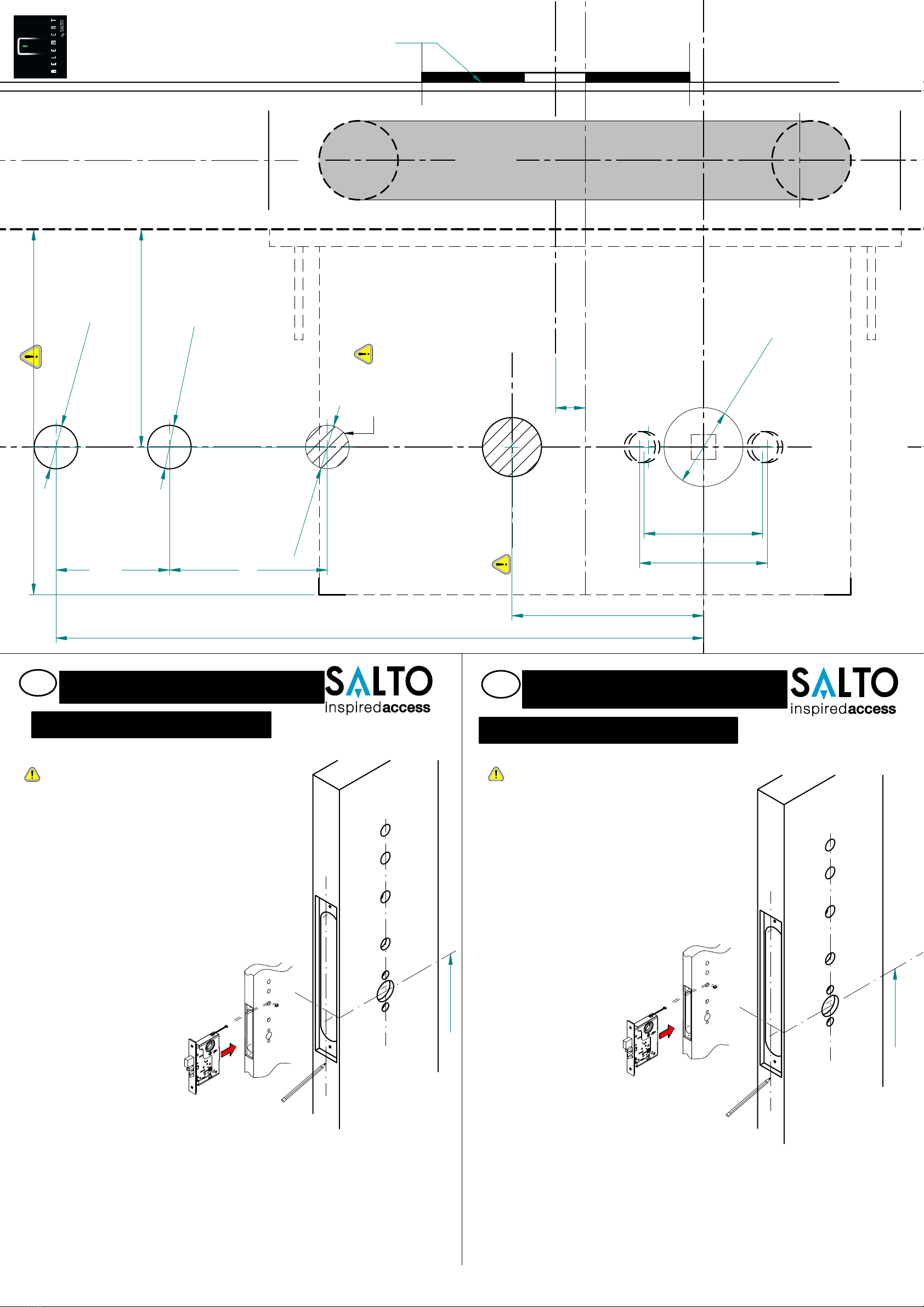
INSTALACION CERRADURA Y CERRADERO
PREPARACION DE LA PUERTA
1. Dibuje una línea horizontal en un lateral y borde delinterior de la puerta,
a la altura deseadade la manilla sobre suelo.
2. Dibuje una línea vertical en el eje del canto de la puerta.
3. Dibuje una línea vertical en el lateral de la puerta (lado interior) para
fijar la entrada y poder alinear la plantilla.
4. Coloque la plantilla en el borde de la puerta. Marque solamente los
agujeros superior e inferior de la caja (A) y frente de la cerradura. Quite
la plantilla: coloque la cara de la cerradura contra el borde de la puerta
con referencia a las marcas. Marque el contorno del frente para realiza
r
el cajeado del mismo.
5. Realice el cajeado del cuerpo de la cerradura y el frente siguiendo las
instrucciones de la plantilla.
6. Coloque la plantilla en el lado interior de la puerta. Marque los agujeros
para la privacidad (B) y manilla (C y D) en la cara lateral. Marque los
correspondientes agujeros para la fijación (E y F) del escudo Aelemnt. El
agujero (F) no tiene que ser pasante, debe tener una profundidad
6mm mayor que el centro de la cerradura.
INSTALACIÓN DE LA CERRADURA DE EMBUTIR
1. Inserte el cable porel agujero (F).
2. Inserte la cerradura en la cavidad.
3. Marque y perfore losagujeros del frente. Sujete con
los tornillos el frente de la cerraduraen su alojamiento.
INSTALACIÓN DEL CERRADERO
1. Centre el hueco del cerradero con el centro del frente de la cerradura.
Tome la referencia con el picaporte, para determinar la altura del
cerradero.
2. Usando el cerradero como plantilla, marcar su perfil, cajear con el
formón y perfore los agujeros para la caja-cerradero. Coloque la caja-
cerradero y sujete el cerradero con los tornillos suministrados.
Comprobar:
- El picaporte y la palanca entran en los huecos del cerradero sin
rozar.
- Holgura entre puerta y marco, entre 2 mm y 4 mm.
PREPARATION DE LA PORTE
1. Marquez la ligne horizontale de coté intérieure et bord de la porte selon
la hauteur à laquelle vous désirez situer la poigné.
2. Marquez une ligne verticale surl’axe du champ de la porte.
3. Marquez une ligne verticale sur l’axe (entre le carré et la têtière), de côté
intérieure de la porte pour déterminer l’entrée et l’alignement du
gabarit.
4. Placez le gabarit sur le champ de la porte.
Marquez seulement les trous supérieurs et inferieurs de l’en-coffrage de
la mortaise (A), sur le champ de la porte. Retirer le gabarit d’installation:
situez la têtière de la mortaise à plat contre le champ de la porte.
Marquez la découpe de la têtière pour son usinage.
5. Réalisez l’usinage du corps de la mortaise et de la têtière suivant les
instructions du gabarit.
6. Placez les trous latéraux pour la privacité et les poignées (C et D) sur la
façade intérieure. Marqué les trous correspondants pour les fixations (E
et F) du écusson électronique. Le trou (F) ne doit pas être passent, sa
profondeur doit être de 6mm plus que lecentre de la serrure.
INSTALATION DE LA MORTAISE
1. Insérez le câble dans le trou (F).
2. Insérez la mortaise dans l’emplacement usiné.
3. Marquez et percez les trous de laplaque frontale. Fixez
la têtière avec les vices dans son logement sur la porte.
INSTALATION DE LA GÂCHE
1. Marquez la position de la gâche en suivant la référence dugabarit.
2. En utilisant la gâche comme référence, marquez le contour et usinez.
Perforez les trous pour le boiter de gâche. Posez le boitier de gâche e
t
fixez la gâche avec les vis fournies.
Vérifications:
- Le pêne demi-tour et le pêne dormant passent par leur logemen
t
de la têtière sans frotter.
- Espace entre la porte et l’encadrement entre 2 et 4mm
INSTALATION DE LA SERRURE
(E)
(E)
(F)
(C)
L
C
OF
BACKSET
(A)
(A)
(B)
L
C
OF
FRONTPLATE
(D)
OF
LEVER
L
C
HEIGHT ABOVE FLOOR
OF
LEVER
L
C
(D)
(E)
(E)
(F)
(C)
L
C
OF
BACKSET
(A)
(A)
(B)
L
C
OF
FRONTPLATE
(D)
OF
LEVER
L
C
HEIGHT ABOVE FLOOR
OF
LEVER
L
C
(D)
36,5()
1-7/16"
50,82" ( )
702-3/4" ( )
LUBRIFICATION
_
____________________________________________________________________________________________________
Toutes les serrures sont lubrifiées à la graisse. Nous recommandons cependant une lubrification périodique des pièces
mobiles avec une graisse de qualité commerciale (tous les 20.000 cycles ou une fois par an), par l’extérieur de la serrure. Cela
peut ajouter des années à la vie de la serrure en réduisant l’usure excessive. Dans des environnements très rudes, la
lubrification doit être effectuée plus fréquemment
.
LUBRICACION
_
____________________________________________________________________________________________________
Todas las cerraduras vienen lubricadas de fábrica con grasa. Recomendamos sin embargo, la lubricación periódica
continuadade piezas móviles con una grasa comercial de calidad (cada 20.000 ciclos ó una vez al año), desde el exterior de
la cerradura. Esto puede agregar años a la vida de la cerradura reduciendo el excesivo desgaste. En ambientes muy severos,
la lubricación se debe realizarcon más frecuencia
.
221373 - -ED.12/08/2013
All contents current at time of publication.
SALTO Systems S.L. reserves the right to change availability of any
item in this catalogue, its design, construction, and/or materials.
Dimension in inches (dimension in millimetres)
O14
9/16"()
O
14
9/16"()
O14
9/16"()
Template 221373
61,62-27/64" ( )
208,38-13/64" ( )
117,54-5/8" ( )
38,11-1/2" ( )
411.625" ( )
O
25,4
O
1"()
9,5()
3/8"
©2013 SALTO Systems S.L.

This manual suits for next models

1

Other Salto Door Lock manuals

Salto LA1T07 Series User manual

Salto

Salto LA1T07 Series User manual

Salto LA1T05 Series User manual

Salto

Salto LA1T05 Series User manual

Salto KPB16 Series User manual

Salto

Salto KPB16 Series User manual

Salto Neo B1 Series User manual

Salto

Salto Neo B1 Series User manual

Salto Neo M1 Series User manual

Salto

Salto Neo M1 Series User manual

Salto LS5 Series User manual

Salto

Salto LS5 Series User manual

Salto WRDB0A4 K Series User manual

Salto

Salto WRDB0A4 K Series User manual

Salto AF i 2 Series User manual

Salto

Salto AF i 2 Series User manual

Salto Neo N x E1 x Series User manual

Salto

Salto Neo N x E1 x Series User manual

Salto Neo S3 Series User manual

Salto

Salto Neo S3 Series User manual

Salto Neo E1 Series User manual

Salto

Salto Neo E1 Series User manual

Salto XS4 Mini User manual

Salto

Salto XS4 Mini User manual

Salto AELEMENT AE i 1 Series User manual

Salto

Salto AELEMENT AE i 1 Series User manual

Salto LA1T37 Series User manual

Salto

Salto LA1T37 Series User manual

Salto SECURITY Ei 020 x dd ff t Series User manual

Salto

Salto SECURITY Ei 020 x dd ff t Series User manual

Salto XS4 Original User manual

Salto

Salto XS4 Original User manual

Salto AF i 0 Series User manual

Salto

Salto AF i 0 Series User manual

Salto XS4 Mini User manual

Salto

Salto XS4 Mini User manual

Salto Ei45 Series User manual

Salto

Salto Ei45 Series User manual

Salto Neo A1 Series User manual

Salto

Salto Neo A1 Series User manual

Salto Comfort E1CD0x00fft User manual

Salto

Salto Comfort E1CD0x00fft User manual

Salto DBolt Touch User manual

Salto

Salto DBolt Touch User manual

Salto XS4 Mini User manual

Salto

Salto XS4 Mini User manual

Salto XS4 Mini User manual

Salto

Salto XS4 Mini User manual

Popular Door Lock manuals by other brands

Purleve Handle 1002 manual

Purleve

Purleve Handle 1002 manual

Dormakaba RCI 6 Series installation manual

Dormakaba

Dormakaba RCI 6 Series installation manual

Lockly DEADBOLT EDITION PGD1128FPW user manual

Lockly

Lockly DEADBOLT EDITION PGD1128FPW user manual

Corporate Locksmiths CL270BLFP manual

Corporate Locksmiths

Corporate Locksmiths CL270BLFP manual

BURG-WACHTER SET 5011 PINCODE Assembly and user's manual

BURG-WACHTER

BURG-WACHTER SET 5011 PINCODE Assembly and user's manual

Philips EasyKey 6000 Series user manual

Philips

Philips EasyKey 6000 Series user manual

Kwikset Smartcode 888 Installation and user guide

Kwikset

Kwikset Smartcode 888 Installation and user guide

SECO-LARM SD-993C-D3Q manual

SECO-LARM

SECO-LARM SD-993C-D3Q manual

Kaba E-PLEX 2000 installation instructions

Kaba

Kaba E-PLEX 2000 installation instructions

GATEMAN S10-FD instruction manual

GATEMAN

GATEMAN S10-FD instruction manual

Milocks QKK-02 quick start guide

Milocks

Milocks QKK-02 quick start guide

Iseo 214E Series INSTRUCTIONS FOR THE INSTALLATION, USE AND MAINTENANCE

Iseo

Iseo 214E Series INSTRUCTIONS FOR THE INSTALLATION, USE AND MAINTENANCE

Locknetics 101+ Installation and programming manual

Locknetics

Locknetics 101+ Installation and programming manual

danalock V3 BT HK SCANDI manual

danalock

danalock V3 BT HK SCANDI manual

hentech IT5500BT Instruction

hentech

hentech IT5500BT Instruction

CAMDEN CX-ED2079-1 installation instructions

CAMDEN

CAMDEN CX-ED2079-1 installation instructions

ANXELL ML-600 installation instructions

ANXELL

ANXELL ML-600 installation instructions

Kaba Peaks Preferred Technical manual

Kaba

Kaba Peaks Preferred Technical manual

manuals.online logo
manuals.online logoBrands
  • About & Mission
  • Contact us
  • Privacy Policy
  • Terms and Conditions

Copyright 2025 Manuals.Online. All Rights Reserved.