Mastervolt MLi 24/160 User manual

USERS MANUAL / GEBRUIKERSHANDLEIDING
BETRIEBSANLEITUNG / MANUEL D’UTILISATION
MANUAL DE UTILIZACION / INSTRUZIONI PER L’USO
Li-ion Battery
Model MLi 12/320 / MLi 24/160
MASTERVOLT
Snijdersbergweg 93
1105 AN Amsterdam
The Netherlands
Tel.: +31-20-3422100
Fax.: +31-20-6971006
www.mastervolt.com Copyright © 2011 Mastervolt, v 3.3 April 2011
ENGLISH: PAGE 1
NEDERLANDS: PAGINA 37
DEUTSCH: SEITE 73
FRANÇAIS: PAGINA 109
CASTELLANO: PAGINA 145
ITALIANO: PAGINA 181

DELIVERY CONTENTS/ OVERVIEW
2Copyright © 2011 Mastervolt / April 2011 / Li-ion Battery MLi 12/320 , MLi 24/160 / EN
DELIVERY CONTENTS
OVERVIEW
Cell management system
Lifting handle
MasterBus connectors
Battery terminal with M10 thread (12V)
M8 thread (24V)
The battery casing contains two lifting handles that cover
the MasterBus connectors and battery terminals.
The handles protect the wiring when folded down.
Negative terminal
(-, black)
No MasterBus
connectors
MasterBus
connectors
Positive terminal
(+, red)
Li-ion battery
MasterBus
cable (6m)
MasterBus
terminato
r
Battery terminal
2x M10 bolt (12V)
2x M8 bolt (24V) This manual
The Li-ion battery MLi 12/320 is a 8 cell Lithium Ion energy storage device with a nominal voltage of 12V
The Li-ion battery MLi 24/160 is a 8 cell Lithium Ion energy storage device with a nominal voltage of 24V
It contains a cell management system which features:
•Cell balancing
•Battery voltage monitoring
•Battery current monitoring
•Pre warning when battery is almost empty (commincation by means of MasterBus)
•Battery temperature monitoring (integrated temperature sensor)
•Communication with other MasterBus devices like chargers and alternators

TABLE OF CONTENTS
EN / Li-ion Battery MLi 12/320 , MLi 24/160 / April 2011 / Copyright © 2011 Mastervolt 3
Copyright © 2011 Mastervolt. All rights reserved.
Reproduction, transfer, distribution or storage of part or all of the contents in this document in any form without the prior written
permission of Mastervolt is prohibited.
TABLE OF CONTENTS: v 3.3 April 2011
DELIVERY CONTENTS.............................................................................................................................................................. 2
OVERVIEW ................................................................................................................................................................................. 2
1SAFETY GUIDELINES AND MEASURES ...................................................................................................................... 5
1.1 General rules......................................................................................................................................................5
1.2 Transportation warnings.....................................................................................................................................5
1.3 Disposal ofLi-ion batteries..................................................................................................................................5
2GENERAL INFORMATION.............................................................................................................................................. 6
2.1 Use of this manual..............................................................................................................................................6
2.2 Validity of this manual ........................................................................................................................................6
2.3 Guarantee specifications....................................................................................................................................6
2.4 Liability ............................................................................................................................................................... 6
2.5 Identification label...............................................................................................................................................6
2.6 Important to know...............................................................................................................................................6
2.7 Use for intended purpose................................................................................................................................... 7
2.8 Organizational measures ...................................................................................................................................7
2.9 Maintenance and repair......................................................................................................................................7
2.10 General safety and installation precautions........................................................................................................7
2.11 Warning regarding life support applications........................................................................................................7
2.12 Warning regarding the use of batteries. .............................................................................................................7
3HOW IT WORKS.............................................................................................................................................................. 8
3.1 Introduction.........................................................................................................................................................8
3.2 Cell management system...................................................................................................................................8
4OPERATION.................................................................................................................................................................... 9
4.1 Charging.............................................................................................................................................................9
4.2 Discharging ........................................................................................................................................................9
4.3 Battery safety Event...........................................................................................................................................9
4.4 MasterBus powering...........................................................................................................................................9
4.5 MasterBus functionality ......................................................................................................................................9
4.6 Temperature.......................................................................................................................................................9
4.7 Manual operation of the Latching Relay.............................................................................................................9
5MASTERBUS................................................................................................................................................................. 10
5.1 What is MasterBus?......................................................................................................................................... 10
5.2 How to set up a MasterBus network................................................................................................................. 11

TABLE OF CONTENTS
4Copyright © 2011 Mastervolt / April 2011 / Li-ion Battery MLi 12/320 , MLi 24/160 / EN
6BEFORE YOU START................................................................................................................................................... 12
6.1 Unpacking ........................................................................................................................................................ 12
6.2 Required tools:................................................................................................................................................. 12
6.3 Location to install.............................................................................................................................................. 12
6.3.1 General............................................................................................................................................ 12
6.3.2 Ventilation........................................................................................................................................ 12
6.4 External cut-off relay ........................................................................................................................................ 12
6.5 Battery temperature sensor.............................................................................................................................. 12
6.6 General installation guidelines.......................................................................................................................... 12
7INSTALLATION AND COMMISSIONING...................................................................................................................... 13
7.1 STEP 1: Installation.......................................................................................................................................... 13
7.1.1 Single battery installation................................................................................................................. 13
7.1.2 Parallel connection, total maximum current < 200 Amps................................................................. 15
7.1.3 Parallel connection, total maximum current > 200 Amps................................................................. 17
7.1.4 Serial connection, using one charger to charge all batteries........................................................... 19
7.1.5 Serial connection, using one charger per battery ............................................................................ 22
7.2 STEP 2: Commissioning .................................................................................................................................. 25
7.2.1 Charger settings.............................................................................................................................. 25
7.2.2 General............................................................................................................................................ 25
7.2.3 Configuration of the Multi Purpose Contact interface (“INT DC Relay”)........................................... 25
7.2.4 Configuration of the Battery Safety Event........................................................................................ 26
8USER INTERFACE (VIA MASTERBUS)....................................................................................................................... 27
8.1 MasterBus menus ............................................................................................................................................ 27
8.2 MasterBus Event data...................................................................................................................................... 28
8.3 Exchanging MasterBus devices ....................................................................................................................... 28
8.4 Basic MasterBus events: Battery Safety Event ................................................................................................ 28
8.5 ADVANCED MasterBus Events ....................................................................................................................... 29
8.6 Events with the Li-ion battery as target ............................................................................................................ 29
9TROUBLE SHOOTING.................................................................................................................................................. 30
10 MAINTENANCE............................................................................................................................................................. 31
10.1 Battery maintenance ........................................................................................................................................ 31
10.2 Taking out of operation..................................................................................................................................... 31
10.3 Storage............................................................................................................................................................. 31
10.4 Battery replacement......................................................................................................................................... 31
11 ORDERING INFORMATION.......................................................................................................................................... 32
12 TECHNICAL INFORMATION ........................................................................................................................................ 33
12.1 Specifications................................................................................................................................................... 33
12.2 Dimensions....................................................................................................................................................... 34
12.3 Charge, discharge characteristic...................................................................................................................... 34
12.4 Fuse to wire...................................................................................................................................................... 34
13 EC DECLARATION OF CONFORMITY ........................................................................................................................ 35

SAFETY GUIDELINES AND MEASURES
EN / Li-ion Battery MLi 12/320 , MLi 24/160 / April 2011 / Copyright © 2011 Mastervolt 5
1 SAFETY GUIDELINES AND MEASURES
1.1 GENERAL RULES
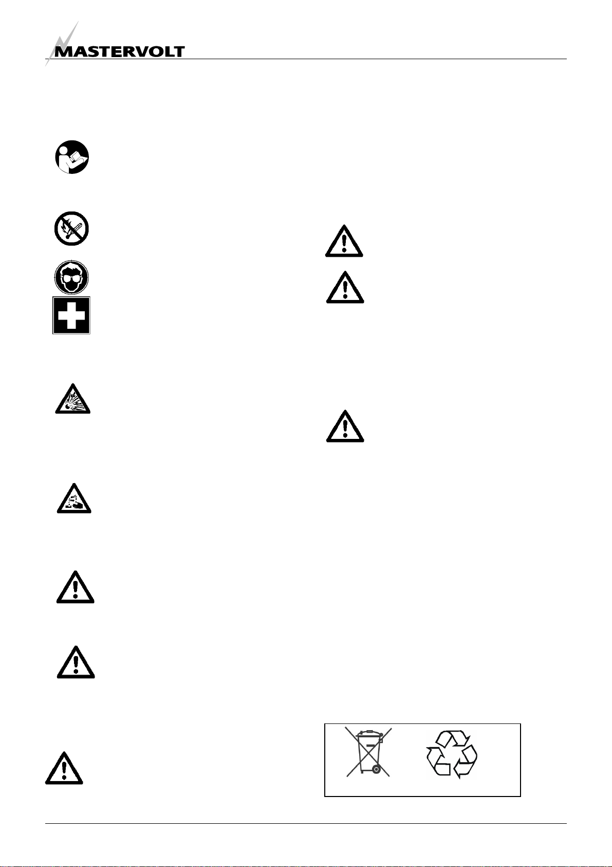
Observe these instructions and keep them
located near the Li-ion Battery for future
reference.
Work on the Li-ion Battery should be carried
out by qualified personnel only.
Do not smoke near the battery!
Do not use any naked flame or other sources
of ignition. Risk of explosion and fire.
While working on the Li-ion Battery wear
protective eye-glasses and clothing.
Any uncovered battery material such as
electrolyte or powder on the skin or in the
eyes must be flushed with plenty of clean
water immediately. Then seek medical
assistance. Spillages on clothing should be
rinsed out with water.
Explosion and fire hazard. Avoid short circuits,
too deep discharges and too high charge
currents. Use insulated tools. Do not place
tools or other items on the Li-ion Battery. Do
not wear any metallic items such as watches,
bracelets, et cetera. In case of fire, you must
use a type D, foam or CO2fire extinguisher.
Never try to open or dismantle the Li-ion
Battery. Electrolyte is very corrosive. In
normal working conditions contact with the
electrolyte is impossible. If the battery casing
is damaged do not touch the exposed
electrolyte or powder because it is corrosive.
Too deep discharges damage the Li-ion
battery seriously and can even be dangerous.
Therefore, use of a MasterBus controlled
external cut off relay is obligatory. Refer to
chapter 6 and 7.
Li-ion Batteries are heavy. If involved in an
accident they can become a projectile! Ensure
adequate and secure mounting and always
use suitable handling equipment for
transportation. Handle with care because Li-
ion Batteries are sensitive to mechanical
shock.
Li-ion batteries can be charged with a voltage
up to 14.6 V (29.2 V). On the other hand, Li-ion
batteries can be discharged down to 11.0
(22.0V). Note that this voltage range (11.0-
14.6V or 22.0-29.2V) is larger than you may
expect from other battery types such as lead-
acid batteries. Be aware that these voltages
may exceed the permitted voltages of the
connected load(s). Therefore appropriate
measures must be taken to avoid damage to
the connected load(s).
Caution! Terminals of the Li-ion Battery are
always alive; therefore do not place items or
tools on the Li-ion Battery.
If charged after the Li-ion battery was
discharged below the Discharge cut-off voltage,
or when the Li-ion battery is damaged or
overcharged, the Li-ion battery can release a
harmful mixture of gasses such as phosphate.
Non-compliance with operating instructions, repairs
made with other than original parts, or repairs made
without authorization render the guarantee void.
1.2 TRANSPORTATION WARNINGS
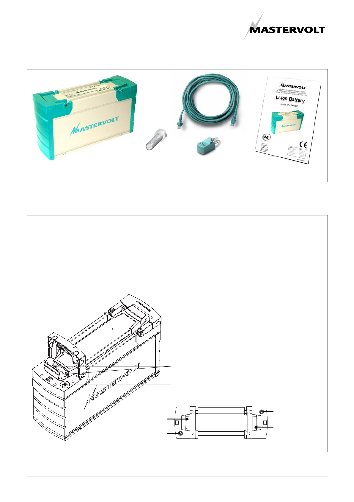
The Li-ion battery must be transported in its
original or equivalent package and in an upright
position.
If the battery is in its package, use soft slings to
avoid damage.
Do not stand below a Li-ion battery when it is
hoisted.
Never lift the battery at the terminals.
Only lift the battery at the handles.
The batteries must be protected against short
circuits, slipping, upsetting or damaging. Li-ion
Batteries must be suitably stacked and secured
on pallets (ADR and RID, special provision
598).
Stacking of pallets is only allowed only if the Li-
ion battery is stored in its original packaging.
1.3 DISPOSAL OFLI-ION BATTERIES
Batteries marked with the recycling symbol should be
processed via a recognized recycling agency. By
agreement, they may be returned to the manufacturer.
Batteries must not be mixed with domestic or industrial
waste
Li-ion non-s
p
illable

GENERAL INFORMATION
6Copyright © 2011 Mastervolt / April 2011 / Li-ion Battery MLi 12/320 , MLi 24/160 / EN
2 GENERAL INFORMATION
2.1 USE OF THIS MANUAL
This manual serves as a guideline for the safe and
effective installation, operation and maintenance of the
Mastervolt Li-ion Battery, models MLi 12/320 and MLi
24/160, further mentioned as “Li-ion Battery” or “Li-ion
Batteries”. It is therefore obligatory that every person who
works on or with the Li-ion Battery must be completely
familiar with the contents of this manual, and that he/she
carefully follows the instructions contained herein.
Installation of, and work on the Li-ion Battery, may only be
carried out by qualified, authorized and trained personnel,
consistent with the locally applicable standards and taking
into consideration the safety guidelines and measures
(chapter 1 of this manual). Keep this manual at a secure
place!
2.2 VALIDITY OF THIS MANUAL
All of the specifications, provisions and instructions
contained in this manual apply solely to the following
products:
Part number Description
66010320 Li-ion Battery MLi 12/320
66020160 Li-ion Battery MLi 24/160
2.3 GUARANTEE SPECIFICATIONS
Mastervolt guarantees that the Li-ion Battery has been
built according to the legally applicable standards and
specifications. Acting not conform instructions and
specifications contained in this manual, may damage the
battery or it may not fulfill its specifications. All of these
matters means that the guarantee becomes invalid.
The guarantee is limited to the costs of repair and/or
replacement of the product. Costs for installation labor or
shipping of the defective parts are not covered by this
guarantee. Battery damage as a result of over and
undercharging is not compensated. You must take
measures to disconnect the Li-ion battery based on
MasterBus alarms generated by this battery, otherwise
guarantee becomes invalid. Use of a MasterBus controlled
external cut off relay is obligatory. (refer to chapter 7). The
period and conditions of this guarantee are laid down in
the general conditions of delivery as registered with the
Chamber of Commerce and Industries in Amsterdam
number 33279951 and are available on request.
Guarantee will void if you fail to use a
MasterBus controlled external cut off relay
2.4 LIABILITY
Mastervolt accepts no liability for:
•consequential damage due to use of the Li-ion
Battery;
•possible errors in the manuals and their results.
2.5 IDENTIFICATION LABEL
The identification label is located at the top side of the Li-
ion Battery, under the grip handles (see figure 1) Important
technical information required for service, maintenance &
secondary delivery of parts can be derived from the
identification label.
Never remove the identification label
2.6 IMPORTANT TO KNOW
Li-ion Batteries do not require topping up water. Never
open the battery. Do not add acid or distilled water.
Figure 1:
Identification label

GENERAL INFORMATION
EN / Li-ion Battery MLi 12/320 , MLi 24/160 / April 2011 / Copyright © 2011 Mastervolt 7
2.7 USE FOR INTENDED PURPOSE
1 The Li-ion Battery is constructed as per the applicable
safety-technical guidelines.
2 Use the Li-ion Battery only:
•in a technical correct condition;
•in a closed, well-ventilated area, protected
against rain, moist, dust and condensation;
•observing the instructions and specifications in
this manual.
WARNING
Never use the Li-ion Battery in locations
where there is danger of gas or dust explosion
or potentially flammable products!.
3 Use of the Li-ion Battery other than mentioned in point
2 is not considered to be consistent with the intended
purpose. Mastervolt is not liable for any damage
resulting from the above.
2.8 ORGANIZATIONAL MEASURES
The user must always:
•have access to the user's manual;
•be familiar with the contents of this manual. This
applies in particular to chapter Safety Guidelines and
Measures.
2.9 MAINTENANCE AND REPAIR
1 If the electrical installation is switched off during
maintenance and/or repair activities, it should be
secured against unexpected and unintentional
switching on:
•switch off all charging systems;
•switch off the connection with the batteries;
•be sure that third parties cannot reverse the
measures taken.
2 If maintenance and repairs are required, only use
original spare parts.
2.10 GENERAL SAFETY AND INSTALLATION
PRECAUTIONS
•Do not expose the Li-ion Battery to rain, snow, spray,
moisture, excessive pollution and condensing
circumstances. To reduce risk of fire hazard, do not
cover or obstruct the ventilation openings. Do not
install the Li-ion Battery in a non-ventilated area,
overheating may result.
•The Li-ion Battery must be provided with a MasterBus
controlled external cut off relay (refer to chapter 7)
•Short circuiting or reversing polarity will lead to
serious damage to the Li-ion Battery, equipment
connected to the Li-ion Battery and the wiring. Fuses
between can not prevent damage caused by reversed
polarity and the warranty will be void.
•Protect the wiring with fuses, according to the
guidelines in this manual.
•Connection and protection must be done in
accordance with local standards.
•Do not work on the Li-ion Battery or system if it is still
connected to a power source. Only allow changes in
your electrical system to be carried out by qualified
electricians.
•Check the wiring at least once a year. Defects such as
loose connections, burned cables etc. must be
corrected immediately.
2.11 WARNING REGARDING LIFE SUPPORT
APPLICATIONS
The Li-ion Battery is not sold for applications in any
medical equipment intended for use as a component of
any life support system unless a specific written
agreement pertaining to such intended use is executed
between the manufacturer and Mastervolt. Such
agreement will require the equipment manufacturer either
to contract additional reliability testing of the Li-ion Battery
parts and/or to commit to undertake such testing as a part
of the manufacturing process. In addition the manufacturer
must agree to indemnify and not hold Mastervolt
responsible for any claims arising from the use of the Li-
ion Battery in the life support equipment.
2.12 WARNING REGARDING THE USE OF
BATTERIES.
Excessive battery discharge and/or high charging voltages
can cause serious damage to batteries. Do not exceed the
recommended limits of discharge level of your batteries.
Avoid short circuiting batteries, as this may result in
explosion and fire hazard. Installation and adjustments of
the Li-ion Battery and its connected components should
only be undertaken by authorised personnel!

HOW IT WORKS
8Copyright © 2011 Mastervolt / April 2011 / Li-ion Battery MLi 12/320 , MLi 24/160 / EN
3 HOW IT WORKS
3.1 INTRODUCTION
This chapter describes the features of the Mastervolt
Lithium Ion battery, a high capacity battery for deep cycle
applications, suitable for parallel operation. Compared to
the traditional lead acid battery, the Li-ion battery offers
70% weight and volume reduction, yet three times as
many charging cycles.
A major advantage of Li-ion batteries is the constant
available power at different discharge loads. Lead Acid
battery capacity decreases at a high discharge current
while the available Li-ion power remains 100%.
Figure 2: Available capacity versus discharge time
(discharge current), Li-ion 24/160 compared to AGM
Key features of the Mastervolt Li-ion battery:
•Deep discharge cycles without noticeable effect on
the cycle life;
•No memory effect;
•No extra energy loss at high discharge levels;
•Short charging time compared to lead acid batteries;
•90 up to 94% energetic efficiency;
•Cell management system for conditioned charge
and discharge regulation to increase safety and
performance;
•Pre warnings about battery state of charge;
•Parallel connectable;
•Weighs about 30% of a comparable lead acid
battery;
•Dimensions are about 30% of a comparable lead
acid battery;
•Maintenance free, no topping up of water;
•No gassing;
•MasterBus compatible;
•Integrated battery terminal isolators.
3.2 CELL MANAGEMENT SYSTEM
The Mastervolt Li-ion battery pack consists of eight cells.
This combination offers both the voltage and power
necessary for all kinds of 12V (24V) equipment. As with all
kind of batteries, some kind of unbalance is always
present in the battery pack. During charging in an
unbalanced battery pack, one or more cells will reach the
maximum charge level before the rest of the cells in the
series string. During discharge the cells that are not fully
charged will be depleted before the other cells in the
string, causing early undervoltage shutdown of the pack.
These early charge and discharge limits reduce the usable
charge in the battery and will shorten the expected lifetime
of the pack.
To avoid this kind of premature failure, the Mastervolt Li-
ion is provided with a Cell Management System. With this
System, each cell is conditioned individually.
Features of the Cell Management System:
•Balancing between the different cells. Normally,
cells in a series string receive identical currents.
With the Cell Management System current from
stronger cells will be transferred to the weaker cells
during the charging/ discharging process and idle
mode;
•Protection of each separate cell from overcharging
or discharging by voltage monitoring of each cell;
•Protection from too deep battery discharges (with
obligatory external cut-off relay);
•Monitoring of temperature. Each separate cell as
well as the external temperature of the battery pack
is being monitored;
•Communication with Mastervolt charge devices to
maximize safety and performance;
•Pre warnings when the state of charge is becoming
low. This feature is particularly useful for ships with
electric propulsion. Reducing vessel speed in time
ensures a safe return in the harbour.
0%
20%
40%
60%
80%
100%
20hr (8A) 10hr (16A) 5hr (32A) 3hr (53A) 1hr (160A)
Discharge time (current)
Available capacity
Li-Ion
AGM

OPERATION
EN / Li-ion Battery MLi 12/320 , MLi 24/160 / April 2011 / Copyright © 2011 Mastervolt 9
4 OPERATION
4.1 CHARGING
Charge the Li-ion Battery within the specifications as
stated in chapter 12. See section 7.2 for recommended
settings of the battery charger.
4.2 DISCHARGING
•Never discharge the Li-ion Battery beyond its
specifications as stated in chapter 12.
•For this purpose, always use of a Latching Relay in
combination with a MasterBus interface to control this
cut-off relay is obligatory. Refer to installation
instructions in chapter 7
4.3 BATTERY SAFETY EVENT
The Li-Ion battery must be protected by means of a
Latching Relay in combination with a MasterBus interface
to control this cut-off relay. This cut-off relay will be
triggered when one of the following conditions is met
during 30 seconds:
•The voltage of one of the Lithium Ion cells is less than
2.0 Volts;
•The voltage of one of the Lithium Ion cells is more
than 4.5 Volts;
•The voltage of the Li-ion Battery is less than 10 Volts
(for a 12V battery) or 20 Volts (for a 24Volt battery);
•The voltage of the Li-ion Battery is more than 15.5
Volts (for a 12V battery) or 31.0 Volts (for a 24Volt
battery)
If the Battery Safety Event has been triggered, act as
follows:
1 Disconnect all loads and all charging devices from the
Li-ion Battery.
2 Reset the Latching Relay(s) to reconnect the Li-ion
battery. To do so, move the Latching Relay(s) in the
REMOTE ON position. See section 4.7.
3 Wait for 1 minute. If the Battery Safety Event triggers
again, do not try to reset the Latching Relay(s) again.
In this case the Li-ion battery is damaged and should
not be used anymore. Move the Latching Relay(s) in
the LOCK OFF position and contact a Mastervolt
representative for assistance.
4 If the Battery Safety Event was not triggered again,
check the battery voltage with a suitable voltage
meter. If the battery voltage is too low, keep the loads
disconnected and start charging the Li-ion battery. If
the battery voltage is too high, check the output
voltage of the charging devices. If OK, discharge the
Li-ion battery for a wile
4.4 MASTERBUS POWERING
The Li-ion battery is able to power the MasterBus network.
Refer to section 8.1 Configuration: MasterBus Power for
setting the battery to MasterBus powering. If enabled, the
MasterBus network will drain the Li-ion Battery slowly.
4.5 MASTERBUS FUNCTIONALITY
Refer to chapter 8 for advanced MasterBus functionality.
4.6 TEMPERATURE
See specifications for recommended operating
temperatures. Higher temperatures will seriously reduce
service life.
The temperature of each cell as well as the temperature of
the entire Li-ion battery is monitored by the cell
management system (see section 3.2). Therefore, do not
use a sensor for temperature compensated charging.
Do not use a temperature sensor for
temperature compensated charging!
4.7 MANUAL OPERATION OF THE LATCHING RELAY
Function Description Action
REMOTE ON To connect the Li-ion Battery to load and
charging devices Push button on top of the relay until
latched
REMOTE OFF To disconnect the Li-ion Battery from
load and charging devices Rotate knob on top of the relay to right
to release button; then rotate knob to
left
LOCK OFF To prevent remote operation Rotate knob on top of the relay to right

MASTERBUS
10 Copyright © 2011 Mastervolt / April 2011 / Li-ion Battery MLi 12/320 , MLi 24/160 / EN
5 MASTERBUS
5.1 WHAT IS MASTERBUS?
All devices that are suitable for MasterBus
are marked by the MasterBus symbol.
MasterBus is a fully decentralized data network for
communication between the different Mastervolt system
devices. It is a CAN-bus based communication network
which has proven itself as a reliable bus-system in
automotive applications. MasterBus is used as power
management system for all connected devices, such as
the inverter, battery charger, generator and many more.
This facilitates communication between the connected
devices, for instance to start the generator when the
batteries are low.
MasterBus reduces complexity of electrical systems by
using less cables. All system components are simply
chained together. For this purpose every MasterBus
device has been equipped with two MasterBus data ports.
When two or more devices are connected through these
data ports, they become a local data network, called the
MasterBus. The results are a reduction of installation costs
as only a few electrical cables and less installation time
are needed.
For central monitoring and control of the connected
devices, Mastervolt offers a wide range of panels which
show full status information of your electrical system at a
glance and a push of a button. Four different panels are
available, from the small Mastervision compatible 120 x
65mm LCD screen up to the full colour MasterView
System panel. All monitoring panels can be used for
monitoring, control and configuration of all connected
MasterBus equipment.
New devices can be added to the existing network in a
very easy way by just extending the network. This makes
the MasterBus a highly flexible network for extended
system configuration, today and in the future.
Mastervolt also offers several interfaces, making even
non-MasterBus devices suitable to operate in the
MasterBus network. For direct communication between
the MasterBus network and a product which is not from
Mastervolt, several interfaces are available. Examples are
the MasterBus NMEA interface and the MasterBus
Modbus interface.
CAUTION: Never connect a non-MasterBus
device to the MasterBus network directly!
This will void warranty of all MasterBus
devices connected.

MASTERBUS
EN / Li-ion Battery MLi 12/320 , MLi 24/160 / April 2011 / Copyright © 2011 Mastervolt 11
5.2 HOW TO SET UP A MASTERBUS NETWORK
Every device that is suitable for the MasterBus network is
equipped with two data ports. When two or more devices
are connected to each other through these ports, they
form a local data network, called the MasterBus.
Keep the following rules in mind:
Figure 3: UTP patch cable
Figure 4: Two Terminators
Figure 5: Power supply
Figure 6: No ring networks
Figure 7: No T-connections
Do not make T-connections in the network.
Do not make ring networks.
The electric power for the network comes from the
connected devices.
At least one device in the network should have
powering capabilities (see specifications).
One powering device can power up to three non-
powering devices.
As all powering devices are isolated galvanically,
multiple powering devices are allowed.
OK
As with all high speed data networks, MasterBus
needs a terminating device on both ends of the
network.
Terminating
device
Terminating
device
OK
Connections between the devices are made by
standard straight UTP patch cables. Mastervolt can
supply these cables. These cables are also commonly
available at computer supply stores.
OK
1-8

BEFORE YOU START
12 Copyright © 2011 Mastervolt / April 2011 / Li-ion Battery MLi 12/320 , MLi 24/160 / EN
6 BEFORE YOU START
During installation and commissioning of the Li-
ion battery, the Safety Guidelines & Measures
are applicable at all times. See chapter 1 of this
manual.
6.1 UNPACKING
After unpacking, check the contents for possible damage.
Do not use the product if it is damaged. If in doubt, contact
your supplier.
6.2 REQUIRED TOOLS:
•Hexagon socket wrench to connect the battery
cables to the Li-ion battery
Model Socket wrench size
Li-ion Battery MLi 12/320 13mm:
Li-ion Battery MLi 24/160 15mm
•Tools to install the wiring.
•For adjustment of setpoints: A MasterBus control
panel. Select one form the table below:
Part number Model
77010305 MasterView Easy MkII
77010400 MasterView System panel
77030100 MasterBus USB interface
(required as interface between your
PC and the MasterBus network)
6.3 LOCATION TO INSTALL
6.3.1 General
•Keep the Li-ion battery away from heat sources. See
specifications for allowed operating temperatures.
•Keep the Li-ion battery away from moist.
•The Mastervolt Li-ion must be installed in upright
position.
•Keep at least 1 cm between two Li-ion batteries for air
flow.
•The Li-ion battery must be secured to its foundation.
6.3.2 Ventilation
The Li-ion battery is provided with ventilation openings for
natural convection. Make sure that the hot air developed
during operation can be discharged. Place the battery in a
sufficiently ventilated room.
6.4 EXTERNAL CUT-OFF RELAY
For safety purposes installation of a Latching
Relay in combination with a MasterBus
interface to control this cut-off relay is
obligatory! Installation and commissioning of
the Li-ion battery requires programming of
events in a MasterBus communication network
to control this external cut-off relay. The installer
must be familiar with the programming of such
events.
6.5 BATTERY TEMPERATURE SENSOR
The Cell Management System has an integrated battery
temperature sensor. See section 8.5 for more information.
Do not use an external battery temperature
sensor.
6.6 GENERAL INSTALLATION GUIDELINES
•Switch off all loads and chargers before starting
installation.
•Batteries in series or parallel must be of the same
brand, type, capacity, nominal voltage and state of
charge. Do not mix old and new batteries. Never use
a Li-ion in parallel or in series with other kind of
batteries, such as lead-acid batteries.
•Use properly sized and reliable, cables, cable lugs
and battery terminals. Tighten all connections. For the
main DC connections use 14.7 to 19.6 Nm / 130 to
170 InLbs torque. Do not over torque as this will
damage the Li-ion Battery beyond repair.
•Unused wiring should be insulated properly to avoid
accidental contact.
•Connect the battery with the correct polarity to the
charger and load(s) (positive pole to positive
terminal). Note that the position of the battery poles
may differ from previously installed batteries! In
installations with a negative earth, connect the
negative cable last of all to prevent short circuiting.
•After connecting the battery cable, close the
protection lids (grip handles of the Li-ion battery) to
prevent incidental touching of the terminals.

INSTALLATION AND COMMISSIONING
EN / Li-ion Battery MLi 12/320 , MLi 24/160 / April 2011 / Copyright © 2011 Mastervolt 13
7 INSTALLATION AND COMMISSIONING
The sections in this chapter describe the minimum requirements for installation and commissioning of the Li-ion battery. Refer
to chapter 8 for advanced functionality.
Installation and commissioning of the Li-ion battery consist of the following steps:
STEP 1 Installation
STEP 2 Commissioning
7.1 STEP 1: INSTALLATION
The way Installation and commissioning should be executed, depends on the configuration in which the Li-ion battery is used.
Check your configuration from the table below and proceed with the indicated section
Configuration Section
Single battery 7.1.1
Parallel connection, total maximum current < 200 Amps 7.1.2
Parallel connection, total maximum current > 200 Amps 7.1.3
Serial connection, using one charger to charge all batteries 7.1.4
Serial connection, using one charger per battery 7.1.5
7.1.1 Single battery installation
7.1.1.1 Required materials
Quantity
@ 12V @ 24V Mastervolt
Part number Description
1 -- 66010320 Li-ion Battery MLi 12/320
-- 1 66020160 Li-ion Battery MLi 24/160
1 1 77030500 MasterBus MPC (Multi Purpose Contact Output)
1 -- 79007700 Latching Relay 12V/300A – Blue Sea Systems, part # 7700
-- 1 79007702 Latching Relay 24V/300A – Blue Sea Systems, part # 7702
1 1 Main Fuse + Fuse base to protect the DC Main Wiring
Fuse rating depending on the cross section of the applied DC Main Wiring, max 200A.
1 1 2A-T Fuse + fuse holder to protect the wiring of the control circuit of the Latching Relay
1 1 MasterBus control panel (see section 6.2)
** ** DC Main Wiring, cross section depending on Main Fuse, max 70mm²
** ** Wiring for the control circuit of the Latching Relay, minimum cross section: 0.5mm²
** ** MasterBus communication cables
** Installation dependent

INSTALLATION AND COMMISSIONING
14 Copyright © 2011 Mastervolt / April 2011 / Li-ion Battery MLi 12/320 , MLi 24/160 / EN
7.1.1.2 Installation instructions
1 Move the Latching Relay in the LOCK OFF position. See section 4.7
2 Connect the DC Main Wiring as indicated in figure 8 but do not place the Main Fuse yet
3 Connect the wiring for the control circuit of the Latching Relay as indicated in figure 8
4 Connect the MasterBus cabling between the devices as indicated in figure 8. Keep the rules in mind as described in
section 5.2. Add a MasterBus control panel to the MasterBus network.
Figure 8: Single battery installation
5 Continue with section 7.2
1. MasterBus MPC
2. Main Fuse
3. 1A-T Fuse
4. Li-ion battery
5. Latching Relay
6. MasterBus control panel
7. DC Main Wiring
8. Control circuit wiring
9. MasterBus cabling
10. MasterBus terminator or
connection to another MasterBus
device
+
-
2
4
3
1
RED
ORANGE
BLACK
BROWN*
YELLOW*
* WIRE NOT USED
5
31
Terminal 2: not connected
6
789
10

INSTALLATION AND COMMISSIONING
EN / Li-ion Battery MLi 12/320 , MLi 24/160 / April 2011 / Copyright © 2011 Mastervolt 15
7.1.2 Parallel connection, total maximum current < 200 Amps
CAUTION: I
If more than 10 Li-ion batteries must be connected in parallel, please contact your Mastervolt supplier for advice.
CAUTION: I
If Li-ion batteries need to be replaced individually, make sure that:
Before reconnection: the open circuit voltage of these batteries must equal the voltage of the parallelled batteries.
After reconnection: MasterBus events need to be reprogrammed for each replaced battery
7.1.2.1 Required materials
Quantity
@ 12V @ 24V Mastervolt
Part number Description
n* -- 66010320 Li-ion Battery MLi 12/320
-- n* 66020160 Li-ion Battery MLi 24/160
1 1 77030500 MasterBus MPC (Multi Purpose Contact Output)
1 -- 79007700 Latching Relay 12V/300A – Blue Sea Systems, part # 7700
-- 1 79007702 Latching Relay 24V/300A – Blue Sea Systems, part # 7702
1 1 Main Fuse + Fuse base to protect the DC Main Wiring
Fuse rating depending on the cross section of the applied wiring, max 200A.
n* n* Fuse + Fuse base to protect the wiring to the Li-ion Battery
Fuse rating depending on the cross section of the applied wiring, max 160A.
1 1 2A-T Fuse + fuse holder to protect the wiring of the control circuit of the Latching Relay
1 1 MasterBus control panel (see section 6.2)
2 2 DC Bus bar to connect the DC Main Wiring
** ** DC Main Wiring, cross section depending on the applied fuses, max. 70mm²
** ** Wiring for the control circuit of the Latching Relay, minimum cross section: 0.5mm²
** ** MasterBus communication cables
* n = Number of Li-ion Batteries installed in parallel, maximum number: 10
** Installation dependent

INSTALLATION AND COMMISSIONING
16 Copyright © 2011 Mastervolt / April 2011 / Li-ion Battery MLi 12/320 , MLi 24/160 / EN
7.1.2.2 Installation instructions
1 Move the Latching Relay in the LOCK OFF position. See section 4.7
2 Connect the DC Main Wiring as indicated in figure 9 but do not place the fuses yet
3 Connect the wiring for the control circuit of the Latching Relay as indicated in figure 9
4 Connect the MasterBus cabling between the devices as indicated in figure 9. Keep the rules in mind as described in
section 5.2. Add a MasterBus control panel to the MasterBus network.
Figure 9: Two or more batteries in parallel, Total maximum current < 200 Amps
5 Continue with section 7.2
1. MasterBus MPC
2. Main Fuse
3. 1A-T Fuse
4. Li-ion battery
5. Latching Relay
6. MasterBus control panel
7. DC Main Wiring
8. Control circuit wiring
9. MasterBus cabling
10. MasterBus terminator or connection to another
MasterBus device
11. Fuse to protect the wiring to the Li-ion Battery
12. DC Bus-bar
+
-
2
4
3
1
RED
ORANGE
BLACK
BROWN*
YELLOW*
* WIRE NOT USED
5
31
Terminal 2: not connected
6
78910
11
12
12

INSTALLATION AND COMMISSIONING
EN / Li-ion Battery MLi 12/320 , MLi 24/160 / April 2011 / Copyright © 2011 Mastervolt 17
7.1.3 Parallel connection, total maximum current > 200 Amps
CAUTION: I
If more than 10 Li-ion batteries must be connected in parallel, please contact your Mastervolt supplier for advice.
CAUTION: I
If Li-ion batteries need to be replaced individually, make sure that:
Before reconnection: the open circuit voltage of these batteries must equal the voltage of the parallelled batteries.
After reconnection: MasterBus events need to be reprogrammed for each replaced battery
7.1.3.1 Required materials
Quantity
@ 12V @ 24V Mastervolt
Part number Description
n* -- 66010320 Li-ion Battery MLi 12/320
-- n* 66020160 Li-ion Battery MLi 24/160
1 1 77030500 MasterBus MPC (Multi Purpose Contact Output)
n* -- 79007700 Latching Relay 12V/300A – Blue Sea Systems, part # 7700
-- n* 79007702 Latching Relay 24V/300A – Blue Sea Systems, part # 7702
1 1 Main Fuse + Fuse base to protect the DC Main Wiring
Fuse rating depending on the cross section of the applied wiring.
n* n* Fuse + Fuse base to protect the wiring to the Li-ion Battery
Fuse rating depending on the cross section of the applied wiring, max 160A.
1 1 2A-T Fuse + fuse holder to protect the wiring of the control circuit of the Latching Relay
1 1 MasterBus control panel (see section 6.2)
2 2 DC Bus bar to connect the DC Main Wiring
** ** DC Wiring from the Li-ion Battery to the busbar, cross section depending on the applied
fuses, max 70mm².
** ** DC Main Wiring, cross section depending on the applied Main Fuse.
** ** Wiring for the control circuit of the Latching Relay, minimum cross section: 0.5mm²
** ** MasterBus communication cables
* n = Number of Li-ion Batteries installed in parallel, maximum number: 10
** Installation dependent

INSTALLATION AND COMMISSIONING
18 Copyright © 2011 Mastervolt / April 2011 / Li-ion Battery MLi 12/320 , MLi 24/160 / EN
7.1.3.2 Installation instructions
1 Move the Latching Relay in the LOCK OFF position. See section 4.7
2 Connect the DC Main Wiring as indicated in figure 10 but do not place the fuses yet
3 Connect the wiring for the control circuit of the Latching Relay as indicated in figure 10
4 Connect the MasterBus cabling between the devices as indicated in figure 10. Keep the rules in mind as described in
section 5.2. Add a MasterBus control panel to the MasterBus network.
Figure 10: Two or more batteries in parallel, Total maximum current > 200 Amps
5 Continue with section 7.2
1. MasterBus MPC
2. Main Fuse
3. 2A-T Fuse
4. Li-ion battery
5. Latching Relay
6. MasterBus control panel
7. DC Main Wiring
8. Control circuit wiring
9. MasterBus cabling
10. MasterBus terminator or connection to another
MasterBus device
11. Fuse to protect the wiring to the Li-ion Battery
12. DC Bus-bar
+
2
3
1
RED
ORANGE
BLACK
BROWN*
YELLOW*
* WIRE NOT USED
5
31
Terminal 2: not connected
6
78
910
12
12
4
ORANGE
RED
BROWN*
YELLOW*
BROWN*
YELLOW*
BROWN*
YELLOW*
11
5
4
11
5
4
11
5
4
11
-

INSTALLATION AND COMMISSIONING
EN / Li-ion Battery MLi 12/320 , MLi 24/160 / April 2011 / Copyright © 2011 Mastervolt 19
7.1.4 Serial connection, using one charger to charge all batteries
When the Li-ion Batteries are connected in series, the charging process must be balanced. This can be done by means of
DC/DC-converter, model MAGIC 24/24-20. When an imbalance is recognized by the The MasterBus SBS Interface (Serial
Balancing System Interface), these DC/DC-converters will be actuated automatically to level the imbalances. For each Li-ion
Battery one DC/DC-converter is required.
CAUTION: I
Serial connection of Li-ion Batteries is only possible with two or more Li-ion Batteries type MLi 24/160. If more
than two Li-ion batteries must be connected in series, always consult your Mastervolt supplier for advice.
Serial connection of Li-ion Batteries type MLi 12/320 is not possible
CAUTION: I
If Li-ion batteries need to be replaced individually, make sure that:
After reconnection: MasterBus events need to be reprogrammed for each replaced battery
7.1.4.1 Required materials
Quantity
@ 24V Mastervolt Part
number Description
n* 66020160 Li-ion Battery MLi 24/160
1 77030500 MasterBus MPC (Multi Purpose Contact Output)
1 79007702 Latching Relay 24V/300A – Blue Sea Systems, part # 7702
2 Main Fuse + Fuse base to protect the DC Main Wiring
Fuse rating depending on the cross section of the applied wiring.
** Fuses + Fuse bases to protect the wiring after each two Li-ion Batteries. Refer to local
regulations. Fuse rating depending on the cross section of the applied wiring.
n* 30A-T Fuse + fuse holder to protect to the DC/DC-converters.
1 2A-T Fuse + fuse holder to protect the wiring of the control circuit of the Latching Relay
1 MasterBus control panel (see section 6.2)
1 77030500 MasterBus SBS Interface (Serial Balancing System Interface)
n* 81300200 DC/DC-converter, model MAGIC 24/24-20
** DC Main Wiring, cross section depending on the applied fuses (max 70mm²)
** DC Wiring to connect the DC/DC converters model MAGIC; cross section: 6mm²
** Wiring for the control circuit of the Latching Relay, minimum cross section: 0.5mm²
** MasterBus communication cables
* n = Number of Li-ion Batteries installed in parallel, maximum number: 10
** Installation dependent

INSTALLATION AND COMMISSIONING
20 Copyright © 2011 Mastervolt / April 2011 / Li-ion Battery MLi 12/320 , MLi 24/160 / EN
7.1.4.2 Installation instructions
1 Move the Latching Relay in the LOCK OFF position. See section 4.7
2 Connect the DC Main Wiring as indicated in figure 11 but do not place the fuses yet
3 Connect the wiring for the control circuit of the Latching Relay as indicated in figure 11
Figure 11: Two or more batteries in series, using one charger to charge all batteries (Only DC-wiring is shown)
1. DC/DC converter, model MAGiC 24/24-20
2. MasterBus Serial Interface
4. 30A-T Fuse (DC/DC-converters)
5. Li-ion battery
6 Fuse after each two Li-ion Batteries
7. DC Fuse Main Wiring (Positve)
8. MasterBus MPC Interface
9. MasterBus control panel
10. MasterBus SBS Interface
11. DC Fuse Main Wiring (Negative)
12. DC main wiring
13. Control circuit wiring
14 DC wiring (DC/DC-converters)
15. DC Fuse Control circuit wiring
16 Latching Relay
+
_
7
6
4
9
12
_+
1
5
10
BROWN*
YELLOW*
11
31
Terminal 2: not connected
RED
2
ORANGE
BLACK
6
8
13 14
15
* WIRE NOT USED
16
This manual suits for next models
1
Table of contents
Other Mastervolt Camera Accessories manuals

Mastervolt
Mastervolt MLI Ultra 12/1250 Original operating instructions

Mastervolt
Mastervolt AGM 55Ah User manual

Mastervolt
Mastervolt 1602 User manual

Mastervolt
Mastervolt MLI-E 12/1200 User manual

Mastervolt
Mastervolt MVSV series User manual

Mastervolt
Mastervolt BATTERY MATE 1602 User manual

Mastervolt
Mastervolt BI703 User manual

Mastervolt
Mastervolt MVG Series User manual

Mastervolt
Mastervolt MLI Ultra 12/2750 Operating manual

Mastervolt
Mastervolt MLI-E 12/1200 Operating manual