Mastervolt MLI Ultra Operating manual

MLI Ultra
LITHIUM-ION BATTERY
12/1250, 24/1250
USER AND INSTALLATION MANUAL
10000018055/01
For the latest version of this manual, visit our website:
Ga om deze handleiding in andere talen te downloaden naar onze website:
Um diese Anleitung in anderen Sprachen herunterzuladen, besuchen Sie bitte unsere Website:
Pour télécharger ce manuel dans d'autres langues, consultez notre site Web :
Para descargar este manual en otros idiomas, visite nuestro sitio web:
Per scaricare questo manuale in altre lingue, visitare la pagina del prodotto sul nostro sito Web:
www.mastervolt.com
EN
NL
DE
FR
ES
IT

2
MLI Ultra 12/1250, 24/1250 –User and Installation Manual
Table of contents
1. SAFETY INSTRUCTIONS ........................... 3
Safety warnings ........................................... 3
Safety guidelines.......................................... 4
2. GENERAL INFORMATION.......................... 5
Liability......................................................... 5
Warranty...................................................... 5
Disclaimer.................................................... 5
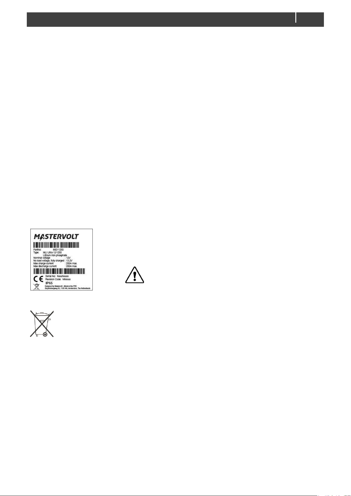
Identification label........................................ 5
Correct disposal of this product.................... 5
3. PRODUCT DESCRIPTION.......................... 6
Status LEDs................................................. 6
Battery switch-button (safety disconnect)..... 7
Battery Management System (BMS)............ 7
Charging...................................................... 7
4. BASIC INSTALLATION···························9
Unpacking.................................................... 9
Location....................................................... 9
Materials needed ......................................... 9
Installation procedure for a single unit........ 10
Adding the MLI Ultra to a MasterBus network
.................................................................. 11
Adding the MLI Ultra to a CZone network... 11
Auxiliary connector..................................... 12
5. CONFIGURATION..................................... 13
DIP switch settings······························· 13
MasterBus DIP switch settings··············· 13
CZone DIP switch settings ····················13
How to change the DIP switch
settings············································13
Configuration in a MasterBus network........14
Monitoring tab ····································14
Alarms tab·········································14
History tab·········································15
Configuration tab·································15
Events tab·········································16
Events sources···································17
Event commands ································18
Stop Charge event ······························18
How to activate MasterBus
powering ··········································18
Configuration in a CZone network...............19
6. BUILDING A BATTERY BANK ...................21
Series and parallel connections..................21
Configuration of a battery bank...................22
Using DIP switches (MasterBus only) ······22
Using MasterAdjust ·····························24
Using CZone Configuration Tool·············24
7. STORAGE AND CARE...............................26
8. TROUBLESHOOTING................................27
9. SPECIFICATIONS......................................28
Technical specifications..............................28
Battery switch –automatic behavior ...........29
Characteristics............................................29

MLI Ultra 12/1250, 24/1250 –User and Installation Manual
3
1. SAFETY INSTRUCTIONS
IMPORTANT SAFETY INSTRUCTIONS
SAVE THESE INSTRUCTIONS
Safety warnings
WARNING!
The battery contains hazardous materials that are stored safely during normal use. Do
not crush, open or drop the battery housing. Do not touch or ingest any of the released
materials or inhale released gasses when accidental leakage of the battery occurs.
Should skin contact, eye contact or inhalation nevertheless occur, take the necessary
first aid measures immediately. Refer to the Material Safety Data Sheet for Mastervolt
Lithium-Ion batteries, which is available on www.mastervolt.com.
WARNING!
Avoid short circuiting batteries as this may result in fire, explosion, electric shock or
release of toxic gas. Use insulated tools only and keep metal objects away from the
battery. Do not wear watches, bracelets, necklaces or other metal objects when working
on the battery. In case of fire, take the necessary firefighting measures immediately.
Refer to the Material Safety Data Sheet for Mastervolt Lithium-Ion batteries, which is
available on www.mastervolt.com.
WARNING!
Short circuits, too deep discharges and too high charge currents will damage the battery
and may result in fire, explosion, electric shock or release of toxic gas. Never charge a
battery:
- after it was discharged below the Battery Safety voltage;
- when the battery is damaged;
- when the battery was over-charged.
If in doubt, contact your Mastervolt dealer.
CAUTION!
When transported, make sure that:
- the battery is in its original package or equivalent;
- the battery is in upright position;
- soft slings are used to avoid damage;
- the battery is only lifted at the handles;
- the battery is handled with care.
Note: The voltage range (12.0-14.6V or 24.0-29.2V) is larger than you may expect from other battery
types such as lead-acid batteries. Be aware that these voltages could exceed the permitted
voltages of the connected load(s).

4
MLI Ultra 12/1250, 24/1250 –User and Installation Manual
Warning regarding life support applications
Mastervolt products are not designed to be used as component of medical equipment, unless
negotiated in the form of a written agreement between customer and/or manufacturer and Mastervolt.
Such agreement will require the equipment manufacturer either to contract additional reliability testing
of the Mastervolt parts and/or to commit to undertake such testing as a part of the manufacturing
process. Furthermore, the manufacturer must agree to indemnify and not hold Mastervolt responsible
for any claims arising from the use of the Mastervolt parts in the life support equipment.
Safety guidelines
- Use the MLI Ultra following the instructions and specifications stated in this manual.
- Work on the MLI Ultra should be carried out by qualified personnel only.
- Non-compliance with operating instructions, repairs made with other than original parts, or repairs
made without authorization render the warranty.
- If programming of events in a MasterBus or CZone network is required, the installer must be familiar
with the programming of such events.
- Connections and safety features must always comply with all local rules and regulations.
- Use cables with an appropriate size.
- Never use the MLI Ultra in situations where there is danger of gas or dust explosion or potentially
flammable products!
- Only use the MLI Ultra in a technical correct condition.
- Only use the MLI Ultra in a well-ventilated area and protect the connectors from moisture and dust.
- Switch off all charging systems and disconnect the MLI Ultra from the electrical installation during
maintenance and/or repair activities.

MLI Ultra 12/1250, 24/1250 –User and Installation Manual
5
2. GENERAL INFORMATION
Liability
Mastervolt cannot be held liable for:
- Consequential damage resulting from the use of the MLI Ultra.
- Possible errors in the included manual and the consequences of these.
- Use that is inconsistent with the purpose of the MLI Ultra.
Warranty
The Mastervolt product warranty covers the MLI Ultra for the first two years after the purchase date, on
the condition that the product is installed and used according to the instructions in this manual.
Installation or use that does not comply with these instructions may result in under performance,
damage or failure of the product and may void this warranty. The warranty is limited to the cost of repair
and/or replacement of the product. Costs of labor or shipping are not covered by this warranty.
Disclaimer
Our products are subject to continual development and improvement. Therefore, additions or
modifications to the products may cause changes to the technical data and functional specifications. No
rights can be derived from this document. Please consult our online Terms & Conditions of Sale.
Identification label
The following picture is only an example!
The identification label is located on the top side of the MLI Ultra. Technical
information required for service and maintenance (part number, serial
number and revision code) can be derived from the identification label.
CAUTION!
Never remove the identification label.
This will void the warranty.
Correct disposal of this product
This product is designed and manufactured with high quality materials and components,
which can be recycled and reused. Act according to your local rules and do not dispose of
your old products with your normal household waste. The correct disposal of your old
product will help prevent potential negative consequences to the environment and human
health.

6
MLI Ultra 12/1250, 24/1250 –User and Installation Manual
3. PRODUCT DESCRIPTION
1. M8 positive terminal
2. M8 negative terminal
3. Provision for removable handle
4. Hold down edges group 31, fit battery group size 49
5. Attachment strap support
6. Protective vent; maintain adequate ventilation around this
opening. Do not touch the membrane!
7. Auxiliary connector
8. MasterBus/CZone connectors
9. Status LEDs and DIP switch
cover
10.Battery switch-button (safety
disconnect)
Figure 1: overview of the MLI Ultra 1250
Status LEDs
Figure 2: status LEDs
LED
Color
Name
Behavior
A
Red
Error
If this LED is on, a BMS error has occurred or cells are damaged. Check
the installation and contact your Mastervolt dealer.
B
Yellow
Battery
state
During normal operation the LED is off.
1 short blink
●●●
State of Charge (SoC) low. Charge the battery.
2 short blinks
●● ●● ●●
CZone network identification (during installation).
3 short blinks
●●● ●●●
Auto cluster configuration error. See section "Using
DIP switches" on page 22.
4 short blinks
●●●● ●●●●
Battery is executing a recovery procedure.
Blinking slowly
▬▬▬
Battery is updating its firmware.
C
Green
Battery
switch
state
When the Battery switch-button is pressed short, this LED indicates the
status of the battery switch.
- Solid on for 1 minute: battery is on (switch is closed).
- Blinking for 1 minute: battery is off (switch is open).
1
0
9
7
2
6
5
3
8
4
1

MLI Ultra 12/1250, 24/1250 –User and Installation Manual
7
Battery switch-button (safety disconnect)
CAUTION!
This built-in battery switch is to safely disconnect the battery. It also disconnects from the
charger!
Figure 3: Battery switch-button
Press short for status; Short press to make LED C show the status of the Battery switch.
•Solid on for 1 minute: battery is on (switch is closed).
•Blinking for 1 minute: battery is off (switch is open).
Press 1 sec; Long press for 1 second to switch-off. LED C will blink.
Press 5 sec; Long press for 5 seconds to switch-on. LED C will light up for 1 minute.
Note: If the battery was switched-off manually, it must be switched-on manually.
Battery Management System (BMS)
The MLI Ultra has a built-in Battery Management System (BMS) and a built-in battery switch. The BMS
protects the battery by automatically controlling the battery switch when thresholds are met. This is
called a 'battery safety'-event. See chapter "SPECIFICATIONS”for the thresholds. An automatically
switch-off is initiated after the following events:
•Cell over- or under-voltage
•Battery over-current
•Over-temperature of the MLI Ultra
•Low State of Charge (SOC)
Likewise, automatically switch-on is initiated when the conditions are safe again.
Charging
The MLI Ultra can be charged with any Mastervolt battery charger, like the ChargeMaster Plus series,
or with a ProMariner ProSport HD or ProNautic for example. Make sure that the charger is Lithium Ion
compatible and meets the MLI Ultra's charge parameters. Set the battery type to MLI or adjust the 3-
step+ (also known as IuoUo) charge characteristic as follows:
Model
Bulk / absorption voltage
Float voltage
12V
14.25 V
13.5 V
24V
28.5 V
27 V
LED B will blink yellow when the state of charge (SOC) is low. Make sure to charge when the SOC is
low to preserve the lifespan.
Recovering from deeply discharge
If the MLI Ultra was deeply discharged, the integrated 1A charger charges the cells to 2.5V. After that, a
self-test on the cells will activate automatically to test if the cells are damaged by the deep discharge.
When the result is ok, the battery will be switched-on, and normal charging can start. When the result is
not ok, LED A will be solid red. In that case, contact your Mastervolt dealer.
Please note that this procedure may take between 30 minutes to 5 hours!

8
MLI Ultra 12/1250, 24/1250 –User and Installation Manual
Charging at low temperature
Do not use a sensor for temperature compensated charging. Temperatures of the battery and its cells
are monitored by the built-in BMS. If the temperature of the MLI Ultra is below 0°C [32°F], an integrated
heater is automatically turned on until 5°C [41°F] is reached or the charger is disconnected. This heater
can also be controlled through MasterBus events or CZone circuits.

MLI Ultra 12/1250, 24/1250 –User and Installation Manual
9
4. BASIC INSTALLATION
Unpacking
The delivery consists of the following parts:
1. MLI Ultra battery with 2x M8 bolt + washer + spring washer, for screw connection
2. 1x automotive battery pole positive (thick) + M8 Allen bolt, for clamp connection
3. 1x automotive battery pole negative (thin) + M8 Allen bolt, for clamp connection
4. Handle
5. 2x Attachment strap
6. MasterBus terminator
7. MasterBus cable (1m)
8. Drop cable CZone/MB (1m)
9. Auxiliary cable (2m)
10. The quick installation manual
Never use a damaged battery. If in doubt, contact your Mastervolt dealer.
Location
- Install the MLI Ultra in a well-ventilated room protected against rain, snow, spray, vapor, bilge,
moisture and dust.
- Keep the MLI Ultra away from heat sources. See specifications for allowed operating temperatures.
- The MLI Ultra must be installed in upright position or on the long side of the case, although upright
mounting is recommended.
Upright position
Long side position
- Keep at least 1cm [3/8"] between two Li-Ion batteries for air flow.
- The MLI Ultra must be secured. The following drawings are examples of mounting options:
With included mounting straps
Hold-downs on long side
(group 49)
With a frame or tray
Materials needed
- Battery charger
- Due to Interrupt Rating, use a T-fuse or an MRBF fuse and a fuse holder.
This manual assumes that an MRBF fuse is used.
- DC wiring
MLI Ultra 12/1250
MLI Ultra 24/1250
Recommended fuse
200 A
100 A
Recommended wire size
70 mm2 [AWG 2/0]
35 mm2 [AWG 2]
11 mm
0.4 inch

10
MLI Ultra 12/1250, 24/1250 –User and Installation Manual
WARNING!
The wire and fuse sizes stated in this manual are only guidelines. Cross section depends on the
maximum system current.
Always comply with all local rules and regulations.
Installation procedure for a single unit
WARNING!
In installations with a negative earth: Connect the negative cable last of all to
prevent short circuiting.
WARNING!
Never mount a stud fuse directly to the battery terminal without a fuse holder! If there is not
enough space, use a separate bus bar to mount the fuse on.
Step 1.Switch off all loads and chargers.
Step 2.Insert the handle into the recesses on the top of the battery.
Step 3.Out of the box, the battery is on (switch is closed). Press the Battery switch-button to switch-off
(safety disconnect). LED C will blink for 1 minute to indicate that the battery is off (switch is
open).
Step 4.Secure the battery in place.
Step 5.Mount an MRBF fuse holder directly on the battery's POSITIVE terminal, add the fuse and the
POSITIVE cable. Tighten the bolt. Never mount a stud fuse directly on the battery terminal.
Always use the isolated fuse holder! Otherwise the fuse will not work! See the following figure.
A. + terminal
B. Fuse holder
C. Fuse
D. Positive cable
E. Plain washer
F. Spring washer
Figure 4: mounting a stud fuse
Connect the negative cable to the –terminal.
Recommended torques: 14.7 –19.6 Nm / 130 –170 InLbs.
Step 6.Option: connect the 6-pin auxiliary connector cable. See page 12 for details.
Step 7.Option: connect communication cables.

MLI Ultra 12/1250, 24/1250 –User and Installation Manual
11
- MasterBus: connect two MasterBus cables (or one cable and one Terminator). See
Figure 5 on page 11.
- CZone: connect the drop cable. On the battery side, plug the connectors into either
of the communication ports. See Figure 6 on page 12.
Step 8.Press the Battery switch-button for 5 seconds to switch the battery on. LED C will be solid on for
1 minute to indicate that the switch is closed.
Step 9.Switch on some loads and verify that they are working. Switch off the load, switch on the
charger and verify (charger status) that the battery is being charged.
To change the default settings according to your needs, either use the DIP switches or a configuration
tool. For optimal use, it is strongly recommended to configure a Stop charge event. See page 18 for
more information.
Adding the MLI Ultra to a MasterBus network
MasterBus is a CAN based, fully decentralized data network for communication between Mastervolt
devices. MasterBus is used as power management system for all connected equipment, such as the
inverter, battery charger, generator and many more. Every device that is compatible with MasterBus is
equipped with two data ports. The devices are simply daisy chained together, forming a local data
network
1. Disconnect a MasterBus cable or Terminator from the closest MasterBus device and connect it to
the MLI Ultra.
2. Connect the new MasterBus cable to the other MasterBus device and then connect to the MLI Ultra.
3. Ensure that the network is properly terminated.
Figure 5: MasterBus cables
Adding the MLI Ultra to a CZone network
The CZone network is an NMEA 2000-compliant CAN-based system. In a CZone network, the MLI
Ultra can be monitored from a remote panel like the Touch 5. The settings can only be adjusted with the
CZone Configuration Tool.
Additional required materials per MLI Ultra:
1. Disconnect the backbone at the closest backbone connection and add in a tee connector (not
included).
2. Reconnect the backbone connection(s) with the new tee connector in place. Ensure that the network
is properly terminated.

12
MLI Ultra 12/1250, 24/1250 –User and Installation Manual
3. Connect the RJ45 CZone/MB drop cable to the black coupler on the tee and then connect to the MLI
Ultra. On the battery side, plug the connectors into either of the communication ports. LED B will
blink to confirm CZone network identification.
Figure 6: CZone drop cable
Auxiliary connector
FUNCTION
WIRE COLOR
PIN
Figure 7: connector
on the MLI Ultra
Analog SoC output
Max rating: 1mA
Green (0 –10VDC)
Black (GND)
6
3
Aux. relay
Max rating: 30VDC/1A
Yellow
White
4
5
Not used
Red
Blue
1
2
Figure 8: six wire ferruled auxiliary cable
•State of Charge (SoC) indication
Wire pair 3&6 can be used to monitor the SoC on external equipment, where 10V = 100% and
0V = 0%. To enable this, select the "SOC 0-10V" option in the Configuration tab, see page 15.
•Auxiliary relay (dry contact)
Wire pair 4&5 can be used to control an external device like a switch, relay or lamp. This is done in
combination with a MasterBus event command or CZone circuit.
RED
BLUE
YELLOW
GREEN
BLACK
WHITE
GND
GND
VDC
0-10v
RELAY

MLI Ultra 12/1250, 24/1250 –User and Installation Manual
13
5. CONFIGURATION
Out of the box, the MLI Ultra is suitable for use in a MasterBus network or as a stand-alone battery. For
CZone and for advanced features, the settings must be adjusted. Most settings can be done through
DIP switches. Advanced or network settings are done from a Windows laptop or notebook with either
the free MasterAdjust or the CZone configuration tool. MasterAdjust software can be downloaded at
www.mastervolt.com. The CZone Configuration Tool software is available to technical CZone
customers from the CZone Portal.
DIP switch settings
By default, all DIP switches are off.
MasterBus DIP switch settings
1. Set DIP switch 1 ON (1).
2. Set DIP switches 2 to 8 to fit your needs. DIP switches 9 and 10 are not used in MasterBus.
DIP switch
2
3
4
5
6
7
8
MasterBus Powering off
MasterBus Powering on
0
1
Event-based 'stop charge' can be setup per charger
Automatic 'stop charge' for ALL Mastervolt chargers
(see section "Stop Charge event" on page 18)
0
1
Cluster setting for multi-unit configuration:
Stand-alone
Replica unit
Primary 12V unit
Primary 24V unit
Primary 36V unit
Primary 48V unit
(see section "Configuration of a battery bank” on page 22)
0
0
0
0
1
1
0
0
1
1
0
0
0
1
0
1
0
1
Auto switch-on enabled
Auto switch-on disabled
0
1
Battery detect disabled
Battery detect enabled
0
1
Battery detect: If the battery is switched-off, there will be no voltage at the poles and some chargers will
not start charging. By enabling the Battery detect option, this is fixed. Note that if a load is connected
that this will slowly drain the battery (5-10mA).
CZone DIP switch settings
1. Set DIP switch 1 to the OFF position (0).
2. Set DIP switch 2 to the OFF position (0).
3. Set DIP switches 3 to 10 to match the unique 'dipswitch' number, used in the CZone network.
How to change the DIP switch settings
Figure 9: DIP switches

14
MLI Ultra 12/1250, 24/1250 –User and Installation Manual
1. Remove the DIP switch cover by loosening the four screws.
2. Use a small screwdriver to carefully change the DIP switch position.
3. Replace the DIP switch cover and fasten with the screws. Make sure that the rubber band is placed
correctly, to make it watertight.
Configuration in a MasterBus network
A display like the SmartRemote or EasyView 5, can be used to monitor the MLI Ultra. Advanced
configuration can be done in MasterAdjust, from a Windows laptop or notebook connected to the MLI
Ultra via a Mastervolt USB Interface. The following tables list the parameters as shown in MasterAdjust.
Monitoring tab
Menu
Description
Battery/Cluster
State of charge
Battery state of charge in %
Time remaining
Time of battery use left at the actual load in hh:mm:ss
Voltage
Battery voltage measured by the cell management system
Current
Current measured by the cell management system
Positive value: charging, negative value: discharging
Temperature
Internal temperature of the battery in °C
Battery switch
Switch close
Button to close the battery switch.
Switch open
Button to open the battery switch.
Switch state
State of the battery switch: open / close / unknown
Note: you need to login as installer to see all following parameters.
Installer
Battery safety
Indication of the occurrence of a Battery Safety event
Stop charge
Indication of the occurrence of a Stop charge event
MB power state
Indication whether MasterBus powering is on or off
Heater
This checkbox is marked when the heater is on
Aux. relay close
Closure of relay wire pair 4&5 of the auxiliary cable
Aux. relay open
Opening of relay wire pair 4&5 of the auxiliary cable.
Voltage
Cell 1 … 8
Voltage of the individual cells
Balancer
Balancer 1…8
Indication of balancing of the individual cells
Temperature
Temperature
Temperature of cells 1, 2-3, 4-5, 6-7, 8
Alarms tab
Menu
Description
Generic
Battery safety
Indication of the occurrence of a Battery Safety event
Overcurrent
Battery current too high
Short circuit
Indication of a short circuit in the MLI Ultra
Capacity low
This alarm is raised when the State of charge (SoC) drops below a preset value
(10% by default)
Cap. Very low
Indicates that the State of charge drops below a preset value (0% by default)
Note: you need to login as installer to see all following parameters:
BMS failure
BMS error

MLI Ultra 12/1250, 24/1250 –User and Installation Manual
15
Menu
Description
Bat. switch err.
Battery switch error
Recovery
failed
This checkbox is marked when the battery recovery has failed
Recovery
active
This checkbox is marked when the battery is recovering
History tab
Menu
Description
Cycle count
The number of cycles so far
Last time 100%
Date of the last time that the MLI Ultra was fully charged
Max. Ah used
The maximum used capacity that the MLI Ultra saw
Lowest voltage
The lowest battery voltage that the MLI Ultra saw
Highest voltage
The highest battery voltage that the MLI Ultra saw
Configuration tab
Menu
Description
Default
Adjustable
range
Name
Name of this device. This name will be
recognized by all devices connected to the
MasterBus network
MLI[serial num
ber]
0-12 chars
Language
Menu language of this device
English
English, Dutch
Serial number
Serial number of the MLI Ultra
(read only)
DIP switches
Status of the DIP switches
0
(read only)
CZone
This checkbox is marked when the MLI Ultra is
setup to work in a CZone network
(read only)
MB power
Off: MasterBus powering disabled.
Automatic: MasterBus power will be switched off
when the main current is in between 1.0A and -
1.0A for more than 24 hours and the battery
voltage has dropped below the float voltage.
Always on: the MLI Ultra will power the
MasterBus network. Note that this will slowly
drain the battery.
Note: MasterBus powering is only available if
DIP switch 2 is ON.
Off
Off / Automatic /
Always on
Auto switch
on
Select this option for automatic control of the
battery switch.
On
On/off
Auto heater
Select this option for automatic control of the
heater.
On
On/off
Processor
Version
Firmware main version
(read only)
Revision
Product version
(read only)
Bootloader
ver.
Bootloader version
(read only)
Note: you need to login as installer to see all following parameters.
Cluster
See also section "Configuration of a battery bank”on page 22
Nr. in series
The number of batteries in series
1
1-10
Nr. in parallel
The number of batteries in parallel
1
1-24
Confirm
topology
Button to confirm the number of batteries in
series and/or parallel

16
MLI Ultra 12/1250, 24/1250 –User and Installation Manual
Menu
Description
Default
Adjustable
range
Event levels
Capacity low
Level below which the Capacity low event can
be triggered
10%
0-100
Cap. very low
Level below which the Cap. very low event can
be triggered
0%
0-100%
Battery full
Level above which the Battery full event can be
triggered
100
0-100%
High
temperature
Internal temperature of the MLI Ultra serves as
an event source
45°C
30-60°C
Low
temperature
Internal temperature of the MLI Ultra serves as
an event source
5°C
30-60°C
Voltage low
Level below which the Voltage low event can be
triggered
12.5V
25.0V
12.25-12.75V
24.5-25.5V
Volt. low
delay
Delay time to trigger the Voltage low event after
the level was reached
10s
1-120s
Last time
100%
Last time fully charged serves as an event
source. To prevent damage the batteries must
be charged to the full 100% regularly.
It is a common misconception that Lithium-Ion
batteries should not be fully charged.
31 days
7-60 days
Installer
DOD
To optimize the battery cycle life, the Depth of
Discharge (DOD) is set to 80%.
80%
20-100%
CAUTION!
Changing the
DoD to 100%
will decrease
the cycle life.
SOC 0-10V
out
Select this option if the auxiliary connector is
used to display the State of Charge.
Test batt
safety
Button to test if the battery switches-off when the
'battery safety'-conditions are met.
Test stop
charge
Button to test if the chargers stop charging when
the 'stop charge'-conditions are met.
Factory
settings
Button to reset the MLI Ultra to its default
settings
Events tab
With MasterBus a device can be programmed to initiate an action at another connected device that
supports MasterBus. This is very helpful in automation of your system and is done by means of event-
based commands.
In the Events tab you can program the MLI Ultra to act as an event source. Events which occur during
the operation of the MLI Ultra will then trigger actions from other devices.

MLI Ultra 12/1250, 24/1250 –User and Installation Manual
17
Field
Description
Value
Event x source
Select an event that triggers an action, for example Relay
open.
See Event source
list
Event x target
Select the device that should act, for example the charger.
Selectable targets
are device
dependent
Event x command
Select the parameter that must be changed on the target
device, for example No connection.
See command list of
the selected device
Event x data
Data translates the input into an output.
•On: status changes to On at first input signal.
•Off: status changes to Off at first input signal.
•Copy: status follows input signal.
•Copy invert: status follows opposite of input.
•Toggle: status changes at 1st signal and back at the 2nd.
Off, On, Copy,
Copy Invert, Toggle
Events sources
Event source
Condition
Comments
Disabled
(no event programmed)
Battery Safety
Battery Safety event occurred and the
safety relay is triggered to disconnect
the battery from loads and charger.
See page 29 for what to do if the
battery was switched-off.
Stop charge
Battery voltage > 14.5V/29V (12V/24V
battery), or voltage or temperature of
one of the individual cells is too high.
Strongly recommended event!
Charging
Battery charging current > 1A
Indicates that the battery is being
charged
Capacity low
State of Charge < Capacity low
See Configuration tab - Event levels
for adjustment of the threshold level
Capacity very low
State of Charge < Capacity very low
See Configuration tab - Event levels
for adjustment of the threshold level
See the related step of the
installation procedure.
Battery full
State of Charge > Battery full.
See Configuration tab - Event levels
for adjustment of the threshold level
Battery > 20%
State of Charge > 19.5 %
Can be used to control the LEDs on
a MasterBus display for example
Battery > 40%
State of Charge > 39.5 %
Battery > 60%
State of Charge > 59.5 %
Battery > 80%
State of Charge > 79.5 %
On
Input
Off
Copy
Toggle
Copy
invert

18
MLI Ultra 12/1250, 24/1250 –User and Installation Manual
Event source
Condition
Comments
Battery 100%
State of Charge > 99.5 %
High temperature
Internal temperature of the MLI Ultra is
too high
See Configuration tab - Event levels
for adjustment of the threshold level
Low temperature
Internal temperature of the MLI Ultra is
too low
See Configuration tab - Event levels
for adjustment of the threshold level
Voltage low
Battery or cell voltage is too low.
See Configuration tab - Event levels
for adjustment of the threshold level
Last time 100%
Last time the MLI Ultra was fully
charged
See Configuration tab - Event levels
for adjustment of the threshold level
Switch open
Switch open event occurred
Switch close
Switch close event occurred
Over current
Battery over current event occurred
Event commands
When the MLI Ultra is configured as an event target by another device, this device can initiate an event
command and an event action to be performed by the MLI Ultra.
Event
command
Meaning
Switch close
The battery switch will be closed.
Switch open
The battery switch will be opened.
Aux. relay
close
Closure of relay wire pair 4&5 of the auxiliary cable.
Aux. relay open
Opening of relay wire pair 4&5 of the auxiliary cable.
Heater on
Turn on the heater of the MLI Ultra (provided that the temperature of the MLI Ultra
is below 0°C [32°F]).
Stop Charge event
Before the battery reaches the limits of the operating specifications, the Stop Charge event is triggered.
When configured, this event forces the Mastervolt charger to switch to the float stage. The charger will
use a lower charger voltage or, in case of parallel connection, switch off. The event will be active for 10
minutes.
WARNING!
If multiple charging devices are used to charge the battery (for instance both an AC powered
charger and an alternator) then the Stop charge event must be configured for each charging
device. The settings depend on the used charger because different chargers have different state
options. Check the manual of the used charger for how to switch the charging state.
In case of a battery bank, this must be done for each battery.
Stop charge can also be selected by setting DIP switch 3 ON. In this case, all connected Mastervolt
chargers will stop charging when a 'Stop charge'-condition is met.
How to activate MasterBus powering
1. First, make sure that DIP switches 1 and 2 are ON.
2. Secondly, to select the option, open MasterAdjust on a notebook/laptop or PC, connected to the
MasterBus network via a USB Interface.
a) Right-click the MLI Ultra and select Login.
b) Select Installer and enter the installer code.
c) Go to the Configuration tab.

MLI Ultra 12/1250, 24/1250 –User and Installation Manual
19
d) From the MB power drop-down list, select Automatic or Always on.
- Automatic: MasterBus power will be switched off when the main current is in between 1.0A and -
1.0A for more than 24 hours and the battery voltage has dropped below the float voltage.
- Always on: the MLI Ultra will always power the MasterBus network. Note that this will slowly
drain the battery.
e) Close MasterAdjust.
Configuration in a CZone network
Either do the configuration while connected to the network or use a prepared configuration file (.zcf).
Ensure that a Dipswitch is assigned.
For detailed information on the configuration, please refer to the CZone®Configuration Tool
Instruction manual, and section Configuration in a MasterBus network on page 14, which describes
the parameters as shown in MasterAdjust.
Precondition: This section assumes that a CZone system is already configured and the CZone
Configuration Tool is open.
1. In the CZone Configuration Tool, from the Modules tab, click the Add button.
2. Enter an understandable Module Name.
3. From the Module Type drop-down list, select Battery (BAT).
4. Each device on a CZone network has a unique CZone address; the Dipswitch. This number must
match the physical DIP switch settings. When connected to the system: either select one from the
drop-down list or edit graphically.
5. From the Battery Type drop-down list, select the required model.
6. Option: click the Advanced Settings button to configure advanced options.
7. NMEA2000 Instances are used to differentiate between multiple monitoring sources.
8. To optimize the battery cycle life, the Depth of Discharge Remaining (DoD) is set to 80%.
CAUTION!
Changing the DoD to 100% will decrease the cycle life.
9. Tick Show Battery Temperature to enable temperature monitoring.
10. Click OK to return to the Module Modification window and then click the Alarm/Switch Settings
button.
11. Set the required alarm levels and Alarm Severities.
Battery level 1, 2 and 3 can be used for State of Charge switching.
12. Click OK to close the Battery Alarm/Switch Settings window.
13. Click OK to close the Module Modification window.
The following steps configure the safety behavior. For example, a Stop Charge switch that stops a
generator and/or battery charger. Or a Battery safety switch that pauses the charging process of an
alternator.
Note: This must be done for all MLI Ultra units and for all charging devices.
14. Click on the Circuits tab and Add a new circuit (bottom left).
15. Enter the Circuit Name (e.g. Stop Charge or Battery Safety) and click OK.
16. Click the Add button in the Circuit Control panel.
17. From the Control Interface drop-down list, select the required MLI Ultra unit.

20
MLI Ultra 12/1250, 24/1250 –User and Installation Manual
18. From the Control Input drop-down list, select Stop Charge.
19. Click OK.
Return to step 16 until all MLI Ultra units have this switch configured.
20. Click the Add button in the Circuit Loads panel.
21. From the Load drop-down list, select the required charger.
22. Set the State to Off.
23. Click the Timer/Advanced Settings button.
24. 'Stop Charge' circuit switch only: from the Control Type drop-down list, select Set Limit and click
OK.
25. Click OK to close the Circuit Load Configuration window.
Optionally, return to step 20 to do this for all chargers.
26. Return to step 14 to configure more circuits.
27. Write the configuration to the network to use the new configuration.
Table of contents
Other Mastervolt Camera Accessories manuals

Mastervolt
Mastervolt BATTERY MATE 1602 User manual

Mastervolt
Mastervolt MLI-E 12/1200 Operating manual

Mastervolt
Mastervolt AGM 55Ah User manual

Mastervolt
Mastervolt MLI-E 12/1200 User manual

Mastervolt
Mastervolt MLi Ultra 12/2500 User manual

Mastervolt
Mastervolt MVSV series Operating manual

Mastervolt
Mastervolt MLI Ultra 12/1250 Operating manual

Mastervolt
Mastervolt BI703 User manual

Mastervolt
Mastervolt MLi 24/160 User manual

Mastervolt
Mastervolt MLi Ultra 12/2500 Guide