Mastervolt DC Master 24/12 50-60A User manual

USERS MANUAL
DC Master
24/12 50-60A
DC-DC converter
MASTERVOLT
Snijdersbergweg 93,
1105 AN Amsterdam
The Netherlands
Tel.: +31-20-3422100
Fax.: +31-20-6971006
www.mastervolt.com Copyright © 2015 Mastervolt, 10000008899/01 - February 2015
ENGLISH

TABLE OF CONTENTS
2February 2015 / DC Master 24/12 50A / EN
TABLE OF CONTENTS: 10000008899/01 - February 2015
1GENERAL INFORMATION.............................................................................................................................................. 3
1.1Use of this manual..............................................................................................................................................3
1.2Product description and application.................................................................................................................... 3
1.3Use of pictograms ..............................................................................................................................................3
1.4Identification label...............................................................................................................................................3
1.5Liability ...............................................................................................................................................................3
2IMPORTANT SAFETY INSTRUCTIONS......................................................................................................................... 4
2.1General ..............................................................................................................................................................4
2.2Explosive gases .................................................................................................................................................4
2.3Warning regarding life support applications........................................................................................................4
2.4Guarantee specifications....................................................................................................................................4
3INSTALLATION............................................................................................................................................................... 5
3.1Before you start..................................................................................................................................................5
3.2Choosing a location to install..............................................................................................................................5
3.3Contents of the delivery:..................................................................................................................................... 5
3.4Installation step-by-step .....................................................................................................................................5
4OPERATION.................................................................................................................................................................... 6
4.1Switching on and off...........................................................................................................................................6
4.2Remote switch function ......................................................................................................................................6
4.3Status LED.........................................................................................................................................................6
4.4Maintenance.......................................................................................................................................................6
5TROUBLE SHOOTING.................................................................................................................................................... 6
6TECHNICAL DATA.......................................................................................................................................................... 7
6.1Specifications.....................................................................................................................................................7
6.2Dimensions.........................................................................................................................................................7
7EC DECLARATION OF CONFORMITY .......................................................................................................................... 8

GENERAL INFORMATION
EN / DC Master 24/12 50A / February 2015 3
1 GENERAL INFORMATION
1.1 USE OF THIS MANUAL
Copyright © 2015 Mastervolt. All rights reserved.
Reproduction, transfer, distribution or storage of part or all
of the contents in this document in any form without the
prior written permission of Mastervolt is prohibited.
All of the specifications, provisions and instructions
contained in this manual apply solely to standard versions
of the DC Master 24/12 50 delivered by Mastervolt.
This manual is only valid for the following model:
Part number Description
81400352 DC Master 24/12 50
Keep this manual at a secure place!
1.2 PRODUCT DESCRIPTION AND
APPLICATION
This Mastervolt DC Master converts a 24V DC voltage to a
12 V DC voltage. Typical application is a 24V battery bank
that powers 12V equipment.
1.3 USE OF PICTOGRAMS
Safety instructions and warnings are marked in this
manual by the following pictograms:
WARNING
A WARNING refers to possible injury to the
user or significant material damage to the
converter if the user does not (carefully) follow
the procedures.
CAUTION!
Special data, restrictions and rules with regard
to preventing damage.
A procedure, circumstance, etc which
deserves extra attention.
1.4 IDENTIFICATION LABEL
Figure 1: Position of the identification label
The identification label is located at the rear side of the DC
Master (see Figure 1) Important technical information
required for service, maintenance & secondary delivery of
parts can be derived from the identification label.
CAUTION!
Never remove the identification label.
1.5 LIABILITY
Mastervolt can accept no liability for:
consequential damage due to use of the DC Master;
possible errors in the manuals and the results thereof.
P/N:
Type: DC Master 24/12 50A
Input: 17...32V
Output: 13.6V 50A nominal 60A Max
81400352
Serial No. F103A0001
Apparatus version
P/N:
Type: DC Master 24/12 50A
Input: 17...32V
Output: 13.6V 50A nominal 60A Max
81400352
Serial No. F103A0001
F103A0001

IMPORTANT SAFETY INSTRUCTIONS
4February 2015 / DC Master 24/12 50A / EN
2 IMPORTANT SAFETY INSTRUCTIONS
READ AND SAVE THESE INSTRUCTIONS
WARNING
This chapter describes important safety and
operating instructions for use of a DC Master
in residential, recreational vehicle (RV) and
marine applications.
2.1 GENERAL
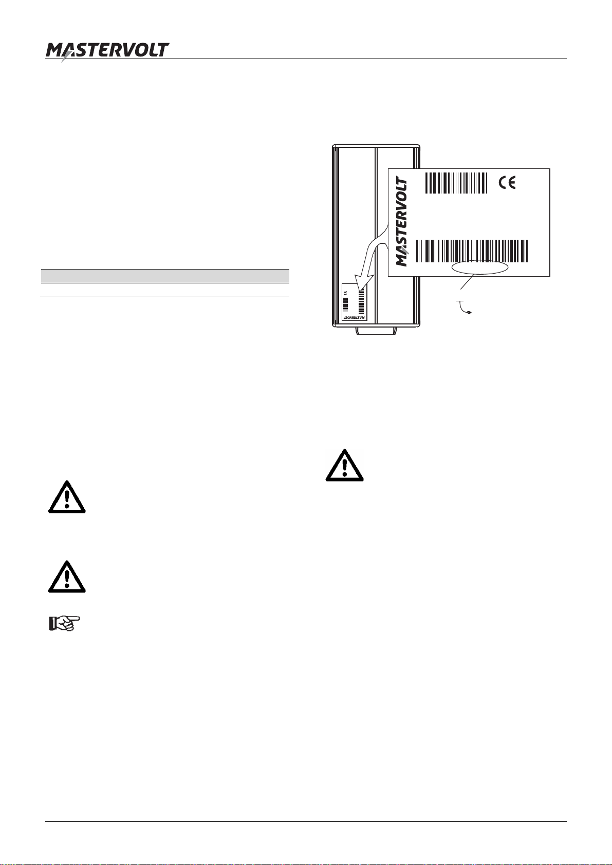
1 Before using the DC Master, read all instructions and
cautionary markings on the DC Master, the batteries,
and all appropriate sections of the manual.
2 To reduce the risk of electric shock – Do not expose
DC Master to rain, snow, spray, moisture, excessive
pollution and condensing circumstances. To reduce
risk of fire hazard, do not cover or obstruct the
ventilation openings. Do not install the DC Master in a
non-ventilated room, overheating may result.
3 Use of an attachment or spare part not recommended
or sold by Mastervolt may result in a risk of fire,
electric shock, or injury to persons.
4 Do not operate DC Master if it has received a sharp
blow, been dropped, or otherwise damaged in any
way; take it to a qualified serviceman.
5 To reduce risk of electric shock, disconnect the DC
Master from both input and output before attempting
any maintenance or cleaning. Turning off controls will
not reduce this risk.
6 Short circuiting or reversing polarity will lead to
serious damage to batteries, DC Master, wiring as
well as accessories. Fuses can not prevent damage
caused by reversed polarity and the warranty will be
void.
7 In case of fire, you must use the fire extinguisher
which is appropriate for electrical equipment.
8 If applied in a marine application in the United States,
external connections to the DC Master shall comply
with the United States Coast Guard Electrical
Regulations (33CFR183, Sub part I).
2.2 EXPLOSIVE GASES
1 WARNING – RISK OF EXPLOSIVE GASES.
WORKING IN VICINITY OF A LEAD-ACID BATTERY
IS DANGEROUS. BATTERIES GENERATE
EXPLOSIVE GASES DURING NORMAL BATTERY
OPERATION. FOR THIS REASON, IT IS OF
UTMOST IMPORTANCE THAT EACH TIME
BEFORE USING THE DC MASTER, YOU READ
THIS MANUAL AND FOLLOW THE INSTRUCTIONS
EXACTLY.
2 To reduce risk of battery explosion, follow these
instructions and those published by battery
manufacturer and manufacturer of any equipment you
intend to use in vicinity of the battery. Review
cautionary marking on these products.
3 DANGER: To reduce the risk of explosion – Never
use the DC Master in situations where there is danger
of gas or dust explosion or area in which ignition-
protected equipment is required.
2.3 WARNING REGARDING LIFE SUPPORT
APPLICATIONS
The DC Master is not sold for applications in any medical
equipment intended for use as a component of any life
support system unless a specific written agreement
pertaining to such intended use is executed between the
manufacturer and Mastervolt. Such agreement will require
the equipment manufacturer either to contract additional
reliability testing of the DC Master and/or to commit to
undertake such testing as a part of the manufacturing
process. In addition the manufacturer must agree to
indemnify and not hold Mastervolt responsible for any
claims arising from the use of the DC Master in the life
support equipment.
2.4 GUARANTEE SPECIFICATIONS
Mastervolt guarantees that this unit has been built
according to the legally applicable standards and
specifications. Should work take place, which is not in
accordance with the guidelines, instructions and
specifications contained in this user’s manual, then
damage may occur and/or the unit may not fulfil its
specifications. All of these matters may mean that the
guarantee becomes invalid.
The guarantee is limited to the costs of repair and/or
replacement of the product. Costs for installation labor or
shipping of the defective parts are not covered by this
guarantee. Refer to your terms of delivery for the
guarantee period.

INSTALLATION
EN / DC Master 24/12 50A / February 2015 5
3 INSTALLATION
3.1 BEFORE YOU START
WARNING
During installation and commissioning of the
DC Master, the Important Safety Instructions
are applicable at all times. See chapter 2 of
this manual.
Make sure that the battery voltage is the same as the
input voltage of the DC Master (24V battery for a 24V
input voltage).
Fuses must be integrated in the positive wires. These
fuse(s) shall be placed last of all. Recommended
fuses:
Recommended Fuse
Input fuse 50A
Output fuse 60A
Remote switch fuse 2A - T
Keep the cable connections as short as possible,
Recommended maximum length of the DC cables: 3 m
/ 10ft. If available, use coloured battery cables: Red for
positive, black for negative. Recommended wire
gauges:
AWG Metric
Input wires (24V) 8 AWG 10 mm²
Output wires (12V) 6 AWG 16 mm²
Remote switch (24V) 16 AWG 1.5 mm²
3.2 CHOOSING A LOCATION TO INSTALL
For an optimal optimum heat discharge, the DC Master
must be installed in a well-ventilated room protected
against rain, vapour, moisture and dust. We advise to
mount the unit in a vertical position with the connecting
cables downward.
Never use the DC Master at a location where there is
danger of gas or dust explosions.
Allow at least 10 cm / 4 inch space around the
apparatus.
Do not mount the DC Master straight above the
batteries because of possible corrosive fumes.
3.3 CONTENTS OF THE DELIVERY:
DC Master 24/12 50-60A
Mounting bracket
4x screws, 4x screw covers, 4x mounting spacers
A 5-way terminal block + wire bridge
This user’s manual;
If one of these items is missing, please contact your
supplier.
3.4 INSTALLATION STEP-BY-STEP
1 Carefully remove the mounting bracket from the DC
Master using a flat-blade screwdriver. Use the
provided screws and dowels to mount the bracket to a
solid and flat surface. Insert the DC Master in the
mounting bracket and press it down until it clicks into
place.
2 See figure 2. Connect the wires as indicated, but do
not place the DC fuse(s) yet. Connect the input wires
first, and then connect the output wires.
a. Without remote switch function: place the
supplied wire bridge between Enable contact (3)
and Positive input (1);
b. With remote switch function: remove the supplied
wire bridge and install Remote switch fuse (8)
and Remote switch (9) as indicated.
3 Check all wiring. If OK, place the DC fuse(s). When
the fuse is placed, internal capacitors may cause a
spark. This is normal.
1 = Positive input (27.2V) 6 = Status LED
2 = Negative input (0V) 7 = Input fuse
3 = Enable (Active high) 8 = Remote switch fuse
4 = Negative output (0V) 9 = Remote switch
5 = Positive output (13.6V) 10 = Output fuse
Figure 2: Wiring diagram
+ –
24V
Load
Belasting
Last
Charge
Carico
Car
g
a
+13.6V
–
1 2 3 4 5
6
7
8
9
10
a
b

OPERATION – TROUBLE SHOOTING
6February 2015 / DC Master 24/12 50A / EN
4 OPERATION
4.1 SWITCHING ON AND OFF
The DC Master does not have a main switch; it is enabled
by inserting the fuse, refer to chapter 3.
Despite its low no-load consumption, the converter should
be disconnected from the supplying battery when it is not
in use to protect the battery from discharging.
4.2 REMOTE SWITCH FUNCTION
The DC Master can be operated remotely by means of an
optional remote switch. See figure 2, reference 9. If the
ENABLE input is powered by the input voltage, the DC
Master is switched on.
4.3 STATUS LED
See Figure 2. The Status-LED (ref. 7) shows the operation
mode of the DC Master.
LED indication Meaning
Continuous green DC Master is working OK
Other Fault condition, refer to chapter 5.
4.4 MAINTENANCE
No specific maintenance is required. If necessary, use a
soft clean cloth to clean the DC Master. Do not use any
liquids or corrosive substances, such as solvents, alcohol,
petrol or abrasive components.
Check the wiring on a regular base. Defects such as loose
connections, burnt wiring etcetera must be corrected
immediately.
5 TROUBLE SHOOTING
If you cannot solve a problem with the aid of this chapter,
contact your local Mastervolt Service Centre. See
www.mastervolt.com/dealer-locator. Make sure you have
the article and serial number (See section 1.4) present if
you have to contact your local Mastervolt Service Center
to solve a problem:
Problem Possible cause What to do?
Output voltage is OK,
Status LED yellow High load Reduce connected load
Output voltage is OK,
Status LED yellow
blinking @ 1Hz
Too high load Reduce connected load, output power is limited
by the DC Master
Output voltage is OK,
Status LED yellow
blinking @ 2Hz
Too high temperature Reduce load and let the converter cool down.
Output power is limited by the DC Master
Converter switches on
and off. Too high load Reduce connected load
Too high temperature Reduce load and let the converter cool down.
Voltage drop over DC cables Check cable length and wire gauge
Loose connections Check connections and replace if necessary
No output voltage, Status
LED is OFF Input fuse blown Check the cause of the blown input fuse(s). Then
replace the fuse(s).
Enable contact is open Connect Enable contact to the positive input (see
section 3.4 and 4.2)
No input voltage or input voltage too low. Check wiring, fuses and battery.
No output voltage, Status
LED flashing green Input voltage too low Check battery voltage, cable length, wire gauge
Input voltage too high Check battery voltage
No output voltage, Status
LED is continuous red. Converter is shut down due to a fault
condition (too high load, short circuit, too
high temperature)
Reduce load and let the converter cool down.
Converter will automatically restart after 1 minute
No output voltage, Status
LED is blinking red. Converter was shut down several times
due to a fault condition Reduce load and let the converter cool down.
Converter must be restarted manually by
switching off and on the DC input voltage

TECHNICAL DATA
EN / DC Master 24/12 50A / February 2015 7
6 TECHNICAL DATA
6.1 SPECIFICATIONS
Model 24/12 50A
Article no. 81400352
Function Non isolated 24V to 12V DC DC converter
Nominal input voltage: 27.2 V (18.0-32.0 V)
Max. input current 30A
Nominal output voltage: 13,6 V +/- 5%
Output current 50 A continuous, 60 A peak during 2 minutes @ 30°C [86 °F]
Ripple 2% of output voltage
Parallel fitting Yes, up to 4 DC Masters of the same model
Efficiency at full load >90%
No load consumption (on/off) 15 / 5 mA
Temperature range -25 to +80 °C [-13 to 176 °F].
Load must be reduced at temperatures between 35 and 80°C [86 and 176 °F].
Cooling Natural convection
Connections 5-way terminal block for wires 1.5mm up to 16mm² [16 up to 6 AWG].
Stripping length: 14mm [0.55 inch]. Tightening torque: 1.7 – 1.8 Nm [15-16 InLbs]
Dimensions in mm (inch): 283 x 125 x 74 mm [11.14 x 4.92 x 2.91 inch] – see also section 6.2
Weight in kg : 1.8 kg [4.0 lbs]
Protection degree IP 53
Specifications are subject to change without prior notice.
6.2 DIMENSIONS
Figure 3: Dimensions in mm [inch]
272 [10.7]
126 [5.0]
58 [2.3] 33 [1.3] 75 [3.0] 84 [3.3]
45 [1.8] 193 [7.6]
1
2

EC DECLARATION OF CONFORMITY
7 EC DECLARATION OF CONFORMITY
We,
Manufacturer Mastervolt
Address Snijdersbergweg 93
1105 AN Amsterdam
The Netherlands
Declare under our sole responsibility that
Product: DC-DC-converter
Model: 81400352 DC Master 24/12 50-60A
Is in conformity with the provisions of the following EC directives:
2004/108/EC (EMC directive); the following harmonized standard has been applied:
EN 60945: 2002 Maritime navigation and radio communication equipment and systems
2011/65/EU (RoHS directive)
Amsterdam, 11 February 2015
H.A. Poppelier
Global R&D Leader
Snijdersbergweg 93, 1105 AN Amsterdam, The Netherlands
Tel : + 31-20-3422100
Fax : + 31-20-6971006
This manual suits for next models
1
Table of contents
Other Mastervolt Media Converter manuals
Popular Media Converter manuals by other brands

KSH International
KSH International SC-101 user manual

Cross Technologies
Cross Technologies 2017-03 instruction manual

B&B Electronics
B&B Electronics McLIM TP-TX/FX user manual

Danfoss
Danfoss iC7 Series installation guide

SOUNDLIGHT
SOUNDLIGHT 3613PWM-H Mk5 RDM operating manual

Addonics Technologies
Addonics Technologies ADSAU3 user guide