Mastervolt 77030460 User manual

USERS MANUAL
Serial Balancing System
Interface
MasterBus Interface for serial balancing of 24V Li-ion batteries
MASTERVOLT
Snijdersbergweg 93,
1105 AN Amsterdam
The Netherlands
Tel.: +31-20-3422100
Fax.: +31-20-6971006
www.mastervolt.com Copyright © 2011 Mastervolt, v 1.0 February 2011
ENGLISH: PAGE 1
NEDERLANDS: PAGINA 17
DEUTSCH: SEITE 33
FRANÇAIS: PAGINA 49
CASTELLANO PÁGINA 65
ITALIANO PÁGINA 81

2February 2011 / SBS interface / EN

CONTENTS
EN / SBS interface / February 2011 3
CONTENTS: v 1.0 February 2011
1GENERAL INFORMATION............................................................................................................................. 4
1.1 Use of this manual.............................................................................................................................. 4
1.2 Important to know ............................................................................................................................... 4
1.3 Guarantee specifications .................................................................................................................... 4
1.4 Liability................................................................................................................................................ 4
2MASTERBUS.................................................................................................................................................. 5
2.1 What is MasterBus?............................................................................................................................ 5
2.2 Event based commands ..................................................................................................................... 5
2.3 How to set up a MasterBus network................................................................................................... 6
3HOW IT WORKS............................................................................................................................................. 7
4INSTALLATION .............................................................................................................................................. 8
4.1 MasterBus connections ...................................................................................................................... 8
4.2 QRS 232 connections......................................................................................................................... 8
4.3 DC connections .................................................................................................................................. 9
5MASTERBUS FUNCTIONS SBS INTERFACE............................................................................................ 10
6MASTERBUS CONFIGURATION OF CONNECTED DEVICES ................................................................. 11
6.1 Li-ion batteries .................................................................................................................................. 11
6.2 MasterBus-Serial Interfaces ............................................................................................................. 11
6.3 Battery Contactor Interface............................................................................................................... 11
6.4 MasterShunt ..................................................................................................................................... 11
7TROUBLE SHOOTING ................................................................................................................................. 12
8ORDERING INFORMATION......................................................................................................................... 14
9TECHNICAL INFORMATION ....................................................................................................................... 15
9.1 Specifications.................................................................................................................................... 15
9.2 Dimensions and connectors ............................................................................................................. 15
10 EC DECLARATION OF CONFORMITY ....................................................................................................... 16

GENERAL INFORMATION
4February 2011 / SBS interface / EN
1 GENERAL INFORMATION
1.1 USE OF THIS MANUAL
Copyright © 2011 Mastervolt. All rights reserved.
Reproduction, transfer, distribution or storage of part
or all of the contents in this document in any form
without the prior written permission of Mastervolt is
prohibited. This manual serves as a guideline for the
safe and effective operation, maintenance and
possible correction of minor malfunctions of the
Serial Balancing System Interface (SBS Interface).
This manual is valid for the following models:
Description Part number
SBS Interface 77030460
Keep this manual at a secure place!
1.2 IMPORTANT TO KNOW
Incorrect installation may lead to damage to the
Serial Balancing System Interface and the
connected Mastervolt devices. Be sure that all
equipment is disconnected from any power source
during installation.
The Magics have a certain power consumption. To
prevent the batteries from being drained, these need
to be charged on a regular base or constantly. This
is particularly important to know if the system is laid
up for a longer period without a possibility for
charging. We then advise to disconnect from the
batteries:
•the Magic DC inputs;
•the MasterBus cables;
•all other loads.
CAUTION: To prevent damage in this
serial balancing system, the Li-ion
batteries need to be charged on a regular
base or constantly.
1.3 GUARANTEE SPECIFICATIONS
Mastervolt guarantees that this product was built
according to the legally applicable standards and
stipulations. If you fail to act in accordance with the
regulations, instructions and stipulations in this
user’s manual, damage can occur and/or the product
will not fulfil the specifications. This may mean that
the guarantee will become null and void.
The standard guarantee period is two years.
IMPORTANT: Additional warranty agreements, like
“Mastervolt system warranty” may contain
restrictions which forbid resetting of historical data
1.4 LIABILITY
Mastervolt accepts no liability for:
•Consequential damage resulting from the use of
the SBS Interface and/or the MasterAdjust
software;
•Possible errors in the included manuals and the
consequences of these;
•Use that is inconsistent with the purpose of the
product.

MASTERBUS
EN / SBS interface / February 2011 5
2 MASTERBUS
2.1 WHAT IS MASTERBUS?
All devices that are suitable for
MasterBus are marked by the MasterBus
symbol.
MasterBus is a fully decentralized data network for
communication between the different Mastervolt
system devices. This CAN-bus based
communication network has proven itself as a
reliable bus-system in automotive applications.
MasterBus is used as power management system
for all connected devices, such as the inverter,
battery charger, generator and many more. This
gives the possibility for communication between the
connected devices, for instance to start the
generator automatically when the batteries are low.
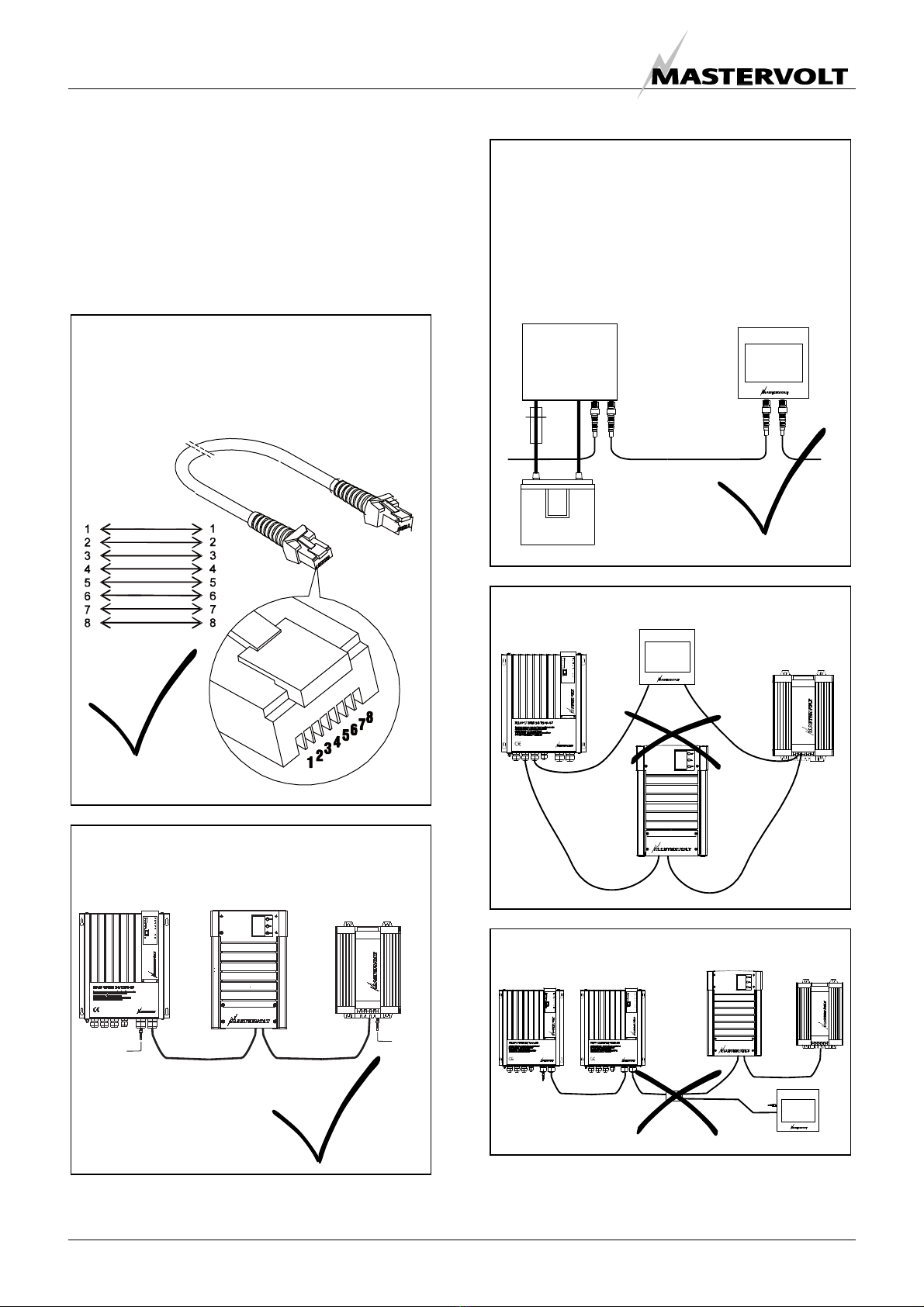
MasterBus reduces complexity of electrical systems
by using UTP patch cables. All system components
are simply chained together. Therefore each device
is equipped with two MasterBus data ports. When
two or more devices are connected to each other
through these data ports, they form a local data
network, called the MasterBus. The results are a
reduction of material costs as only a few electrical
cables are needed and less installation time.
For central monitoring and control of the connected
devices Mastervolt offers a wide range of panels
which show full status information of your electrical
system at a glance and a push of a button. Three
different panels are available, from the MasterView
Easy up to the full colour MasterView System panel.
All monitoring panels can be used for monitoring,
control and configuration of all connected MasterBus
equipment.
New devices can be added to the existing network in
a very easy way by just extending the network. This
gives the MasterBus network a high degree of
flexibility for extended system configuration, not only
today, but in the future as well!
Mastervolt also offers several interfaces, making
even non-MasterBus devices suitable to operate in
the MasterBus network. For direct communication
between the MasterBus network and a product
which is not from Mastervolt, the Modbus interface is
recommended.
CAUTION: Never connect a non-
MasterBus device to the MasterBus
network directly! This will void warranty of
all MasterBus devices connected.
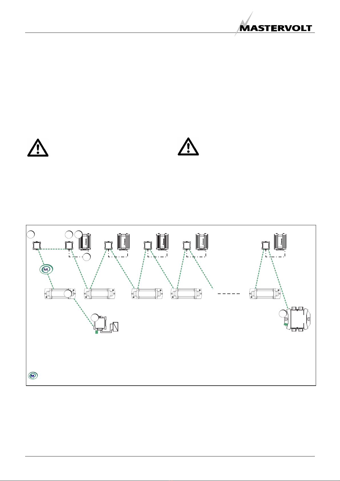
2.2 EVENT BASED COMMANDS
With MasterBus each device can be configured to
initiate an action at another connected device. This
is done by means of event based commands, for
instance in a correct Serial Balancing System, at the
Li-ion event Battery Emergency the Battery
Contactor Interface can switch a relay to disconnect
the load.

MASTERBUS
6February 2011 / SBS interface / EN
2.3 HOW TO SET UP A MASTERBUS
NETWORK
Every device that is suitable for the MasterBus
network is equipped with two data ports. When two
or more devices are connected to each other
through these ports, they form a local data network,
called the MasterBus.
Keep the following rules in mind:
Figure 1: UTP patch cable
Figure 2: Two Terminators
Figure 3: Power supply
Figure 4: No ring networks
Figure 5: No T-connections
Do not make T-connections in the network.
Do not make ring networks.
The electric power for the network is supplied by
the connected MasterBus devices.
At least one device in the network should have
powering capabilities (see specifications).
One powering device can power up to three non-
powering devices.
As all powering devices are galvanic isolated,
multiple powering devices are allowed.
OK
As with all high speed data networks, MasterBus
needs a terminating device on both ends of the
network.
Terminating
device
Terminating
device
OK
Connections between the devices are made by
standard straight UTP patch cables. Mastervolt
can supply these cables. These cables are also
commonl
y
available at com
p
uter su
pp
l
y
stores.
OK
1-8

HOW IT WORKS
EN / SBS interface / February 2011 7
3 HOW IT WORKS
The series connected Li-ion batteries transmit their
voltages via MasterBus to the SBS Interface which
calculates the average voltage. The interface then
configures the Magic DC-DC converters via RS232.
The Magics in their turn regulate the Li-ion batteries
to the average voltage via DC cables.
Figure 6: Working principle of Serial Balancing
See figure 6. B1 to B3 represent the Li-ion batteries,
M1 is the Magic between battery B1 and B2, M2
between B2 and B3 and M3 back from B3 to B1. If
the voltage of the output battery is lower than the
average voltage, current will flow to this battery until
the voltage reaches the average value.
NOTE: The average voltage is measured all the
time. So, if a current flow results in a lower or higher
average voltage, this is corrected for.
Figure 7: Principle current scheme
Figure 7 shows the current flows in the Serial
Balancing System. If the battery voltage of B2 is
lower than the average voltage, M1 “pumps” current
to B2, using B1 as power source. M3 uses B3 as
power source and feeds current to B1 if necessary.
B1 B2 B3
M1 M2 M3

INSTALLATION
8February 2011 / SBS interface / EN
4 INSTALLATION
4.1 MASTERBUS CONNECTIONS
What you need:
•Serial Balancing System Interface (included)
•Maximum 10 24V Li-ion batteries for serial
connection
•One Magic 24/24-20 DC-DC converter for each
battery
•One MasterBus-Serial Interface per Magic for
connection to the MasterBus network
•MasterBus connection cable (included)
CAUTION: The DC-DC converter used in
this system must have galvanic isolation
and 24V input and output voltage.
Mastervolt offers the Magic 24/24-20.
Refer to chapter 6 for MasterBus
configuration.
See figure 8.
•Insert the MasterBus connection cables into the
MasterBus ports of the Serial Balancing System
Interface (1).
•Connect the Serial Interfaces (2), one per Magic
(3) and the Li-ion batteries (5)
To ensure sufficient MasterBus powering, one Li-ion
battery can power up to three Serial Interfaces. We
recommend to use a zig-zag way of connecting the
MasterBus devices.
CAUTION: The Li-ion MasterBus powering
mode is default in state Off.
Make sure, enough MasterBus devices are
configured to power the network, otherwise
the MasterBus communication decays or
even stops!
4.2 QRS 232 CONNECTIONS
The Magic communicates with the MasterBus-Serial
Interface via a QRS 232 cable (4). Refer to the
Magic and MasterBus-Serial Interface manual for
more information.
Figure 8: Serial Balancing System Interface, MasterBus connections and routing
1. SBS interface
2. MasterBus-Serial Interface
3. Magic DC-DC converter
MasterBus cablin
g
4. RS 232 cabling
5. Li-ion battery
9. Assembly for Battery Contactor
11. MasterShunt (optional)
23
4
1
11
_
9
5

INSTALLATION
EN / SBS interface / February 2011 9
4.3 DC CONNECTIONS
What you need:
•Serial Balancing System Interface (included)
•Maximum 10 Li-ion 24V batteries for serial
connection
•One Magic for each battery
•Four 25A fuses (for both Magic input and output
cables, closest possible to the batteries)
•Suitable DC cables
•One suitable fuse for every two Li-ion batteries
For instructions on how to connect the DC wiring to
the Magic and Li-ion terminals, we refer to the
corresponding manuals.
Figure 9: SBS Interface, DC connections
See figure 9.
In order to guarantee the specifications and to
prevent Li-ion battery damage, appropriate
measures must be taken to disconnect the load from
the batteries. The Assembly for Battery Contactor (9)
in the load cabling is an option to accomplish this.
MasterBus event configuration is essential for
correct functioning of the Serial Balancing System.
Refer to the Li-ion battery manual and the Battery
Contactor Interface manual for more information.
A MasterShunt (11) for battery monitoring has been
integrated in the system. It only measures the
voltage of one battery, but it’s main task is to
measure the current through all batteries and so
determine the State of Charge. Refer to the
MasterShunt manual for more information.
To prevent damage as a result of too
high voltage, the MasterShunt is allowed
to measure one battery only.
1. SBS interface (no DC connections)
3. Magic DC-DC converter
5. Li-ion battery
6. 25 A fuse (four per Magic)
7. One 48V fuse per two Li-ion batteries in series
connection (for safety reasons in case of maintenance),
value depending on cabling
8. Load fuse near the positive battery pole,
value depending on load cabling
9. Assembly for Battery Contactor
10. Load
11. MasterShunt (optional)
12. Battery positive DC cable
13. Battery minus DC cable
14. Magic positive DC cable
15. Magic minus DC cable

MASTERBUS FUNCTIONS SBS INTERFACE
10 February 2011 / SBS interface / EN
5 MASTERBUS FUNCTIONS SBS INTERFACE
This chapter describes the MasterBus functions available with the SBS Interface.
Monitoring Description Default Range
State SBS Interface state. Incomplete cfg. means the
configuration was not completed yet and the interface
still not functions properly.
Balanced,
Balancing,
Incomplete cfg.
Battery (V) Total voltage of the series connected battery bank.
Battery (A) Current through the series connected battery bank.
UAvg (V) (login required)
Max-Min (V) (login required)
Convert to go (login required)
Alarms
Incomplete cfg. Configuration was not completed, setup not done. SBS
Interface does not work (correctly). Refer to Setup done
in this table for conditions to complete the configuration.
Batt.disconn.’d Battery disconnected. A Battery configured for serial
balancing is not found on the MasterBus network.
Magic
disconn.‘d
A Magic configured for serial balancing is not found on
the MasterBus network. This means the corresponding
Serial Interface is not connected properly via RS232 or it
is not found on the network.
Configuration
Language Set the menu language. English See specifications
Device name Any name you wish with 12 characters max. SBS Interface 12 characters max
Battery X Select one of the listed serial numbers for battery X.
X ranges 1 – 10. Minimum 2 serial numbers must be
entered.
Select…
Magic Y Select one of the listed MasterBus-Serial Interface serial
numbers for Magic number Y. Y relates to battery
number X, it ranges 1 – 10.
Select…
Reset settings Reset the SBS Interface to factory settings (installer
login required).
- -
Setup done Confirmation the setup has been done. If the setup is
accepted, the Installer login is terminated. The menu
changes to End user level. In the menu, only Monitoring
group General remains and the Configuration groups
Batteries and Magics become read only.
NOTE: The setup is accepted only if these three
conditions are met:
•At least 2 battery serial numbers have been
selected;
•An equal number of MasterBus-Serial Interfaces
have been selected;
•No serial numbers have been entered more than
once.
NOTE: The setup menu will reappear until this has been
done.
- -

MASTERBUS CONFIGURATION OF CONNECTED DEVICES
EN / SBS interface / February 2011 11
6 MASTERBUS CONFIGURATION OF CONNECTED DEVICES
Described is the example of 4 Li-ion batteries in
series connection. Connected in this MasterBus
network are:
•1x SBS Interface (Refer to chapter 5);
•4x Li-ion battery MLi 24/160;
•4x MasterBus - Serial Interface ;
•1x Battery Contactor Interface;
•1x MasterShunt.
NOTE: To do all adjustments, the MasterBus-Serial
interfaces and the Magics must be powered.
Besides, all communication wires, including RS232,
must be connected.
6.1 LI-ION BATTERIES
Serial balancing is possible for Mastervolt MLi
24/160 batteries only. As the Li-ion batteries are
connected in series, the Battery Contactor Interface
must be configured to switch off the load
immediately when no matter what battery is “in
trouble”. The configuration below must be repeated
for all batteries connected.
Source Target Command Data
Emergency BCI
Contactor
Status Copy
invert/Off *
* Copy invert means the Battery Contactor switches
on as soon as the Emergency stops,
Off means the Battery Contactor must be activated
to switch On manually, after the Emergency has
stopped. Which option to choose, depends on the
system used.
CAUTION: The SBS Interface is suitable
for serial balancing of the Mastervolt MLi
24/160 batteries only. Never use other
batteries or combinations of different
batteries!
6.2 MASTERBUS-SERIAL INTERFACES
These interfaces transmit the MasterBus data to the
Magics. For configuration, the Magic must be
powered and the RS232 cable must be installed.
Otherwise the MasterBus-Serial interface does not
“see” the Magic and settings cannot be done.
Next step is to select the mode Stabilize, to check
the option SBS guard (Balancing) and to uncheck
the option Use DIP Switches. The MasterBus-Serial
Interfaces will switch on the Magics. They also
configure the Magics to use the average voltage as
a setpoint for the series connected batteries.
The voltage settings in the table below protect the Li-
ion batteries against over and undervoltage.
Variable Values for 24V Li-ion
batteries
Mode Stabilize
Use DIP Switches Unchecked
Shutdown voltage 16.00 V
Low input off (V) 20.00 V
Low input on (V) 22.00 V
High input off (V) 32.00 V
High input on (V) 30.00 V
Delay time 30 s
Current limit 80%
SBS Guard Checked
CAUTION: The Serial Balancing System
only functions correctly if you
check the option SBS guard (Balancing),
uncheck the option DIP Switches and
select the mode Stabilize on the
corresponding MasterBus – Serial
Interface.
6.3 BATTERY CONTACTOR INTERFACE
The Battery Contactor Interface switches off the load
at battery Emergency, refer to section 6.1.
6.4 MASTERSHUNT
Refer to section 4.3.

TROUBLE SHOOTING
12 February 2011 / SBS interface / EN
7 TROUBLE SHOOTING
Contact your local Mastervolt Service Centre if you cannot correct a problem with the aid of the malfunction table
below. See www.mastervolt.com for an extended list of Mastervolt Service Centres.
Failure Possible cause What to do
No MasterBus
activity is present.
There is no MasterBus powering device
connected or switched on.
Connect and/ or switch on the MasterBus
powering device manually (like the
MasterShunt).
The Serial Balancing System Interface has not
been connected to the serial port.
Check serial cable and connections between
the Serial Balancing System Interface and the
serial port.
The green LED on
the interface is not
illuminated or
blinking. The Serial Balancing System Interface has not
been connected to the MasterBus port.
Check MasterBus cables and connections.
Connected device is switched off. Switch on connected device
Error in the wiring. Check the serial cables. You need Cross
wired serial cables (1 to 6), no MasterBus
cables.
The connected
device cannot be
found.
Wrong connections in the MasterBus serial
Interface. The MasterBus cable shall not be
linked to a non-MasterBus connector like
RS232. And the serial cable shall not be linked
to the MasterBus connector.
Check the connections.
After a setting change, MasterBus
communication is delayed.
Wait for a few seconds.
Error in the wiring. Check MasterBus cables and serial cable.
You need Cross wired (1 to 6) serial cables
(no Straight wired cables).
No terminating device placed at the ends of
the network.
Check if terminating devices are installed on
both ends of the MasterBus network (see
manual of the MasterBus powering device).
MasterBus network is configured as a ring
network.
Ring networks are not allowed (see manual of
the MasterBus powering device). Check the
connections of the network.
No
communication
between the
connected device
and the
MasterBus
network.
T-connections in the MasterBus network. Check if there are no T-connections in the
network. T-connections are not allowed (see
manual of the MasterBus powering device).
Wrong setting of the language at the Serial
Interface.
Click on the “Language” menu and select the
desired language.
Wrong language
is displayed.
Wrong setting of the language at the
MasterBus display.
Each separate connected device can have its
own language setting, including the display.
See user’s manual of the display.
Magic does not
balance
The MasterBus-Serial Interface has switched
off the Magic output.
Nothing, if there are no MasterBus alarms.
Otherwise, check the alarms, see SBS
Interface Alarms in this table.
After pressing
Setup Done, the
Setup screen
reappears
SBS Interface configuration was not
completed. Configuration is essential for
functioning of this interface.
Perform the configuration correctly, refer to
chapter 5 Configuration.

TROUBLE SHOOTING
EN / SBS interface / February 2011 13
SBS Interface alarms (alarm message may show after 30 seconds)
Incomplete cfg. SBS Interface configuration was not
completed.
Refer to chapter 5 Configuration.
Batt.disconn.’d A configured battery is not found on the
MasterBus network, refer to chapter 5, Alarms.
Check all MasterBus wires and MasterBus
powering. Have enough Li-ion batteries been
configured to power MasterBus?
Magic
disconn.‘d
A configured Magic is not found on the
MasterBus network, refer to chapter 5, Alarms.
Check all MasterBus wires and MasterBus
powering. Have enough Li-ion batteries been
configured to power MasterBus? Also check
the RS232 wires between the Serial
Interfaces and the Magics.

ORDERING INFORMATION
14 February 2011 / SBS interface / EN
8 ORDERING INFORMATION
Part number Description
77030460 Serial Balancing System Interface
77040000* MasterBus terminating device*
66020160 Li-ion Battery MLi 24/160
81300200 Magic 24/24-20 DC-DC converter
77030450 MasterBus-Serial Interface
77031700 Battery Contactor Interface
77020100 MasterShunt
77010305 MasterView Easy MkII
77040020 MasterBus connection cable (UTP patch cable), 0,2m / 0.6ft
77040050 MasterBus connection cable (UTP patch cable), 0,5m / 1.6ft
77040100 MasterBus connection cable (UTP patch cable), 1,0m / 3.3ft
77040300 MasterBus connection cable (UTP patch cable), 3,0m / 10ft
77040600* MasterBus connection cable (UTP patch cable), 6,0m / 20ft*
77041000 MasterBus connection cable (UTP patch cable), 10m / 33ft
77041500 MasterBus connection cable (UTP patch cable), 15m / 49ft
77042500 MasterBus connection cable (UTP patch cable), 25m / 82ft
77050000 Complete set to assemble UTP patch cables. Delivery includes: 100m / 330ft UTP cable, 50 pcs.
modular jacks and crimping tool
* These parts are standard included with the delivery of the Serial Balancing System Interface
Mastervolt can offer a wide range of products for your electrical installation, including an extended program of
components for your MasterBus network or MasterVision switchboard.
See our website www.mastervolt.com for a complete overview of all our products

TECHNICAL INFORMATION
EN / SBS interface / February 2011 15
9 TECHNICAL INFORMATION
9.1 SPECIFICATIONS
Model: Serial Balancing System Interface
Article number: 77030460
Manufacturer: Mastervolt Amsterdam, the Netherlands
Delivery includes: Interface, Serial connection cable, MasterBus cable, MasterBus
terminating device, User’s manual
Function of instrument: Regulating the voltages of up to 10 Li-ion 24V batteries in series
connection, using MasterBus communication
Maximum battery voltage difference allowed 0.5 V
MasterBus menu languages English, Nederlands
MasterBus Powering capabilities: No
Power consumption: 144 mW
Weight Approx. 60 gr
Protection degree: IP 21
Dimensions: See drawing below
9.2 DIMENSIONS AND CONNECTORS
= MasterBus connector
Figure 10: Dimensions in mm (inch) and connectors
4,5 [0.18]
69 [2.7]4.0 [0.16]
33 [1.3]
33 [1.3]
6.0 [0.24]
78 [3.1]
32 [1.3]
4.0 [0.16]

EC DECLARATION OF CONFORMITY
10 EC DECLARATION OF CONFORMITY
We,
Manufacturer Mastervolt
Address Snijdersbergweg 93
1105 AN Amsterdam
The Netherlands
Declare under our sole responsibility that the product:
Article number Product name
77030460 Serial Balancing System Interface
is in conformity with the provisions of the following EC directives:
EC EMC directive 89/336/EEC and amendments 92/31/EEC, 93/68/EEC,
Safety directive 2006/95/EC.
The following harmonized standards have been applied:
Generic emission standard: EN 50081-1:1992
Generic Immunity standard: EN 50082-1:1997
Low voltage standard: EN 60950: 2000
Amsterdam, 26/01/2011
Mastervolt international B.V.
H.A. Poppelier
Product manager Marine & Mobile
Snijdersbergweg 93, 1105 AN Amsterdam, The Netherlands
Tel : + 31-20-3422100
Fax : + 31-20-6971006
Table of contents
Other Mastervolt Recording Equipment manuals

Mastervolt
Mastervolt MasterBus CANopen Interface User manual

Mastervolt
Mastervolt MasterBus User manual

Mastervolt
Mastervolt MasterBus Philippi User manual

Mastervolt
Mastervolt MasterBus PowerCombi Interface Operating manual

Mastervolt
Mastervolt MasterBus User manual

Mastervolt
Mastervolt MasterBus LIN Interface Operating manual

Mastervolt
Mastervolt MasterBus - Inverter Interface User manual

Mastervolt
Mastervolt MasterBus AC Master Interface Operating manual

Mastervolt
Mastervolt 77030300 User manual