manuals.online logo
Brands
  1. Home
  2. •
  3. Brands
  4. •
  5. Mastervolt
  6. •
  7. Recording Equipment
  8. •
  9. Mastervolt 77030300 User manual

Mastervolt 77030300 User manual

USERS MANUAL / GEBRUIKERSHANDLEIDING
BETRIEBSANLEITUNG / MANUEL D’UTILISATION
MANUAL DE UTILIZACION / INSTRUZIONI PER L’USO
MasterBus
Tanklevel Interface
Interface between tank level sensor and MasterBus
MASTERVOLT
Snijdersbergweg 93,
1105 AN Amsterdam
The Netherlands
Tel.: +31-20-3422100
Fax.: +31-20-6971006
www.Mastervolt.com
Copyright © 2009 Mastervolt v 1.2 October 2009
ENGLISH: PAGE 1
NEDERLANDS: PAGINA 5
DEUTSCH: SEITE 9
FRANÇAIS: PAGINA 13
CASTELLANO: PÁGINA 17
ITALIANO: PÁGINA 21
2October 2009 / Tank Level Interface EN
1 GENERAL INFORMATION
1.1 Use of this manual
Copyright © 2009 Mastervolt. All rights reserved.
Reproduction, transfer, distribution or storage of part
or all of the contents in this document in any form
without the prior written permission of Mastervolt is
prohibited.
This manual serves as a guideline for the safe and
effective operation of the Tanklevel Interface.
Keep this manual at a secure place!
1.2 Guarantee specifications
Mastervolt guarantees that this product was built
according to the legally applicable standards and
stipulations. If you fail to act in accordance with the
regulations, instructions and stipulations in this
user’s manual, damage can occur and/or the
product will not fulfil the specifications. This may
mean that the guarantee will become null and void.
IMPORTANT: Additional warranty agreements, like
“Mastervolt system warranty” may contain
restrictions which forbid resetting of historical data
The standard guarantee period is two years after
date of purchase.
1.3 Liability
Mastervolt can accept no liability for:
•consequential damage due to use of the
Tanklevel Interface;
•possible errors in the manuals and their results;
•use that is inconsistent with the purpose of the
product.
CAUTION!
Never remove the identification label.
2 OPERATION
2.1 Tank level monitoring
The Tanklevel Interface is able to monitor any
volume level in your system, using any powered or
non powered electric sensor that complies with the
specifications. A typical application of this interface
is monitoring the water or fuel tank level in a ship.
For this purpose, a float sensor must be mounted.
2.2 MasterBus functions
The table below shows the Interface MasterBus
functions. These functions can be visualised by
means of a MasterView display or the free
downloadable MasterAdjust software. See
www.mastervolt.com
Monitoring Description Default Range
Level Tank level expressed in % - 0-100%
Volume Tank level expressed in liters or gallons -
Almost full Option to allow an alarm for an almost full tank Not checked Not checked, checked
Almost empty Option to allow an alarm for an almost empty tank Not checked Not checked, checked
Voltage Sensor voltage in V 0 0-63 V
Current Sensor current in mA 0 0-20 mA
Resistance Sensor resistance in Ohm 0 0-300 Ohm
Alarms
Almost full Alarm to indicate the tank is almost full Not checked Not checked, checked
Almost empty Alarm to indicate the tank is almost empty. Not checked Not checked, checked
Configuration
Language Set the Tanklevel Interface menu language English See specifications
Name Any name you wish with 12 characters max Tanklevel 12 characters max
Unit Three different volume units are available. The
interface automatically converts these units.
Liter Liter,US gallon,UK gallon
Events
Event 1 source Configure Up to 63 events using this interface’s
MasterBus alarms as source. For more
information on events, see www.mastervolt.com
Disabled Disabled, Almost full,
Almost empty
EN / Tank Level Interface / October 2009 3
Configuration for installers only
Sensor type The sensor signal is a voltage, current or
resistance.
Resistive Resistive, current,
voltage
Sensor power
Option for powered sensors. Smart: the sensor is
switched On only if necessary. * See below
Off Off, On, Smart
Sensor damping Sensor fluctuations can be damped to different
levels. The heavier the damping, the larger the
fluctuations that are damped.
Light Light, medium , heavy
Tank type This option allows for indicating the fluid type
contained in the tank or its filling type. Example: a
fresh water tank empties on use and a grey water
tank fills on use.
Fuel Fuel, Fresh water,
Grey water, Black
water, Empties on use,
Fills on use
Tank volume Enter the tank volume as specified.
The volume is expressed in the unit selected.
0 Liter 0-65535 Liter,
0-17314 US Gallon,
0-14416 UK Gallon
Almost full alrm Volume percentage at which the alarm Almost Full
must take place.
100 % 0-100%
Almst.empty alrm Volume percentage at which the alarm Almost
Empty must take place.
0 % 0-100%
Calibration This interface is calibrated by determining at
which level the tank is full and empty. The
interface calculates the tank level by interpolation.
- Tank full, Tank empty
* For Smart powering, your sensor must be able to
produce a reliable signal within 100 milliseconds,
regardless the tank conditions. If you are not sure,
choose On first, calibrate and read the
corresponding AD values. Choose Smart next and
calibrate again. If the AD values compare well, your
sensor is convenient for Smart powering.
3 INSTALLATION
Insert the MasterBus cables, then connect the
sensor cables to the screw terminal 3 (if necessary) ,
4 and 5, see below. Finally connect the battery
cables (1, 2) if necessary.
Connection scheme of the Tanklevel Interface
1. Battery positive
2. Battery negative
3. Switched power positive
4. Sensor signal
5. Sensor negative
6. Communication led
MasterBus connector
4 TECHNICAL INFORMATION
Model: Tanklevel Interface
Article number: 77030300
Delivery also includes: Screw terminal, MasterBus cable, MasterBus Terminating device, User’s manual
Function of instrument: Processing tank level data for MasterBus, using a (non) powered electric sensor;
providing switched power to powered sensors
Battery voltage 0-63 V (< 200 mA), equals to the sensor supply voltage
Sensor voltage 0-70 V
Sensor resistance 0-300 Ohms
Sensor current 0 (4)-20 mA
Power consumption 280 mW
Languages available: English,Nederlands,Deutsch,Français,Castellano,Italiano,Norsk,Svenska,Suomi, Dansk
Din rail mounting: Yes, Din rail 30 mm [1.2 inch]
Protection degree: IP 21
Dimensions: 66 x 78 x 32 mm [2.6 x 3.1 x 1.3 inch]; see drawing below
Weight: Approx. 90 gr [0.20 lb] including screw terminal
5 EC DECLARATION OF CONFORMITY
This product is in conformity with the provision of the EC EMC directive 89/336/EEC
and amendments 92/31/EEC, 93/68/EEC. Standards applied:
Generic emission standard: EN 50081-1:1992,
Generic Immunity standard: EN 50082-1:1997,
Safety directive 2006/95/EC, with the following standard,
Low voltage standard: EN 60950: 2000.
Screw terminal
= MasterBus connector
Dimensions in mm (inch) and connections
4,5 [0.18]
69 [2.7]4.0 [0.16]
33 [1.3]
33 [1.3]
6.0 [0.24]
78 [3.1]
32 [1.3]
4.0 [0.16]
Snijdersbergweg 93, 1105 AN Amsterdam, The Netherlands
Tel : + 31-20-3422100
Fax : + 31-20-6971006
Email : [email protected]

Other Mastervolt Recording Equipment manuals

Mastervolt MasterBus PowerCombi Interface Operating manual

Mastervolt

Mastervolt MasterBus PowerCombi Interface Operating manual

Mastervolt MasterBus User manual

Mastervolt

Mastervolt MasterBus User manual

Mastervolt MasterBus CANopen Interface User manual

Mastervolt

Mastervolt MasterBus CANopen Interface User manual

Mastervolt MasterBus User manual

Mastervolt

Mastervolt MasterBus User manual

Mastervolt MasterBus AC Master Interface Operating manual

Mastervolt

Mastervolt MasterBus AC Master Interface Operating manual

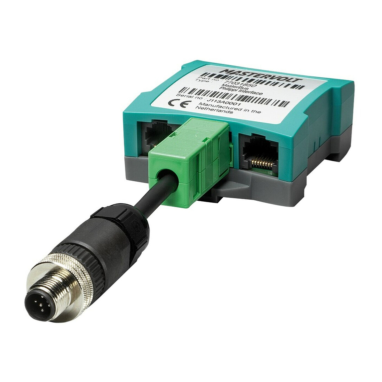
Mastervolt MasterBus Philippi User manual

Mastervolt

Mastervolt MasterBus Philippi User manual

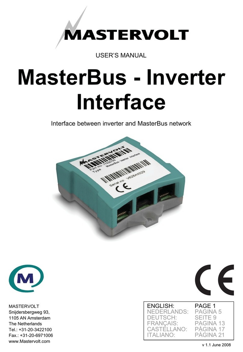
Mastervolt MasterBus - Inverter Interface User manual

Mastervolt

Mastervolt MasterBus - Inverter Interface User manual

Mastervolt MasterBus LIN Interface Operating manual

Mastervolt

Mastervolt MasterBus LIN Interface Operating manual

Mastervolt 77030460 User manual

Mastervolt

Mastervolt 77030460 User manual

Popular Recording Equipment manuals by other brands

Sennheiser HZR 414-1 manual

Sennheiser

Sennheiser HZR 414-1 manual

Yamaha MU90 owner's manual

Yamaha

Yamaha MU90 owner's manual

Omnitronic DXM-0808 operating instructions

Omnitronic

Omnitronic DXM-0808 operating instructions

Yamaha PLG100-VH Getting started guide

Yamaha

Yamaha PLG100-VH Getting started guide

Lexicon 300 V3.0 -  GUIDE REV 1 owner's manual

Lexicon

Lexicon 300 V3.0 - GUIDE REV 1 owner's manual

HEKA Elektronik LIH 8+8 manual

HEKA Elektronik

HEKA Elektronik LIH 8+8 manual

Roland EV-1-WL Connection guide

Roland

Roland EV-1-WL Connection guide

McCauley Sound M Series Operation manual

McCauley Sound

McCauley Sound M Series Operation manual

LEGRAND 5739 94 installation manual

LEGRAND

LEGRAND 5739 94 installation manual

Andrew CommScope RET Master Operation manual

Andrew

Andrew CommScope RET Master Operation manual

Extron electronics RGB 124 user guide

Extron electronics

Extron electronics RGB 124 user guide

MFJ signal enhancer II mfj-752d instruction manual

MFJ

MFJ signal enhancer II mfj-752d instruction manual

Profoto Air Remote TTL-O user guide

Profoto

Profoto Air Remote TTL-O user guide

Beyerdynamic CA 4588 operating instructions

Beyerdynamic

Beyerdynamic CA 4588 operating instructions

midiplus AudiolinkPLUS 4x4 owner's manual

midiplus

midiplus AudiolinkPLUS 4x4 owner's manual

Korg Pandora PX1 owner's manual

Korg

Korg Pandora PX1 owner's manual

Behringer X-DANTE quick start guide

Behringer

Behringer X-DANTE quick start guide

Lab.gruppen PLM Series quick start guide

Lab.gruppen

Lab.gruppen PLM Series quick start guide

manuals.online logo
manuals.online logoBrands
  • About & Mission
  • Contact us
  • Privacy Policy
  • Terms and Conditions

Copyright 2025 Manuals.Online. All Rights Reserved.