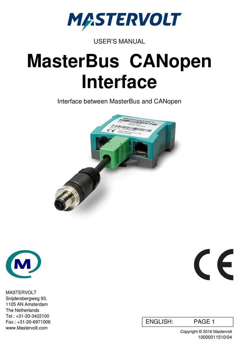
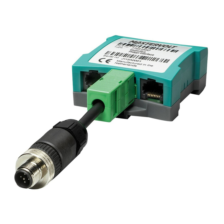
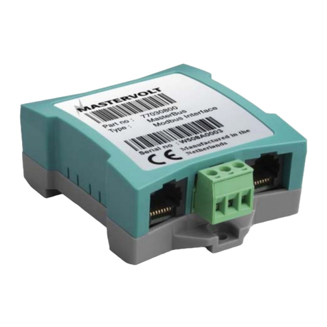
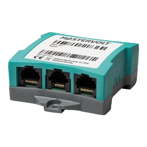
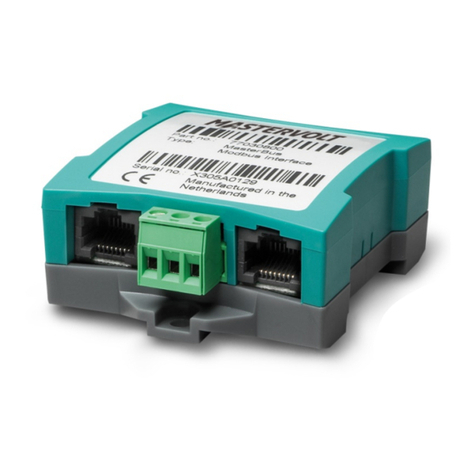
Mastervolt MasterBus User manual

USERS MANUAL / GEBRUIKERSHANDLEIDING
BETRIEBSANLEITUNG / MANUEL D’UTILISATION
MANUAL DE UTILIZACION / INSTRUZIONI PER L’USO
MasterBus–Serial Interface
Interface between serial bus and MasterBus network
MASTERVOLT
Snijdersbergweg 93,
1105 AN Amsterdam
The Netherlands
Tel.: +31-20-3422100
Fax.: +31-20-6971006
mastervolt.com
ENGLISH: PAGE 1
NEDERLANDS: PAGINA 9
DEUTSCH: SEITE 17
FRANÇAIS: PAGINA 25
CASTELLANO: PÁGINA 33
ITALIANO: PÁGINA 41
MAS_TL_004_0411
Copyright © 2011 Mastervolt, v 2.1 March 2011

2March 2011 / MasterBus–Serial interface / EN
CONTENTS V 2.1 March 2011
1 GENERAL INFORMATION ...................................................................................................................................... 2
2 MASTERBUS ........................................................................................................................................................... 3
3 INSTALLATION ........................................................................................................................................................ 3
4 COMMUNICATION................................................................................................................................................... 4
5 ORDERING INFORMATION..................................................................................................................................... 6
6 TROUBLE SHOOTING ............................................................................................................................................ 6
7 TECHNICAL INFORMATION ................................................................................................................................... 7
8 EC DECLARATION OF CONFORMITY................................................................................................................... 8
CONTENTS AND GENERAL INFORMATION
1 GENERAL INFORMATION
1.1 USE OF THIS MANUAL
Copyright © 2011 Mastervolt. All rights reserved.
Reproduction, transfer, distribution or storage of part or
all of the contents in this document in any form without
the prior written permission of Mastervolt is prohibited.
This manual serves as a guideline for the safe
and effective operation, maintenance and possible
correction of minor malfunctions of the MasterBus -
Serial interface.
This manual is valid for the following models:
Description Part number
MasterBus–Serial Interface 77030450
Keep this manual at a secure place!
The English version has 8 pages.
1.2 IMPORTANT TO KNOW
Incorrect installation may lead to damage to the
MasterBus–Serial interface and the connected
Mastervolt devices. Be sure that all equipment
is disconnected from any power source during
installation.
1.3 GUARANTEE SPECIFICATIONS
Mastervolt guarantees that this product was built
according to the legally applicable standards and
stipulations. If you fail to act in accordance with the
regulations, instructions and stipulations in this user’s
manual, damage can occur and/or the product will
not full the specications. This may mean that the
guarantee will become null and void.
IMPORTANT: Additional warranty agreements, like
“Mastervolt system warranty” may contain restrictions
which forbid resetting of historical data.
1.4 LIABILITY
Mastervolt can accept no liability for:
• Consequential damage resulting from the use of the
MasterBus-Serial interface and/or the MasterAdjust
software;
• Possible errors in the included manuals and the
consequences of these;
• Use that is inconsistent with the purpose of the
product.

3
EN / MasterBus–Serial interface / March 2011
MASTERBUS
2 MASTERBUS
2.1 WHAT IS MASTERBUS?
All devices that are suitable for MasterBus are
marked by the MasterBus symbol.
MasterBus is a fully decentralized data network for
communication between the different Mastervolt
system devices. It is a CAN-bus based communication
network which has proven itself as a reliable bus-
system in automotive applications. MasterBus is
used as power management system for all connected
devices, such as the inverter, battery charger,
generator and many more. This gives the possibility
for communication between the connected devices, for
instance to start the generator when the batteries are
low.
MasterBus reduces complexity of electrical systems
by using UTP patch cables. All system components
are simply chained together. Therefore each device is
equipped with two MasterBus data ports. When two
or more devices are connected to each other through
these data ports, they form a local data network, called
the MasterBus. The results are a reduction of material
costs as only a few electrical cables are needed and
less installation time.
3 INSTALLATION
3.1 CONNECTION
What you need:
❑MasterBus-Serial interface (included)
❑MasterBus connection cable (included, 6m)
❑RS232 crossed wire (included)
See gure 1
• Insert the MasterBus connection cables into the
MasterBus data ports of the MasterBus–Serial
interface.
• Connect the Serial connection cable between the
MasterBus–Serial interface and the Serial port of your
device.
☞
Only the RS232 devices mentioned in chapter
4 are suitable for using the MasterBus–Serial
interface.
For central monitoring and control of the connected
devices Mastervolt offers a wide range of panels which
show full status information of your electrical system
at a glance and a push of a button. Four different
panels are available, from the small Mastervision
compatible 120 x 65mm LCD screen up to the full
colour MasterView System panel. All monitoring panels
can be used for monitoring, control and conguration of
all connected MasterBus equipment.
New devices can be added to the existing network
in a very easy way by just extending the network.
Mastervolt also offers several interfaces, making even
non-MasterBus devices suitable to operate in the
MasterBus network
For direct communication between the MasterBus
network and a product which is not from Mastervolt,
the Modbus interface is recommended.
CAUTION: Never connect a non-MasterBus
device to the MasterBus network directly!
This will void warranty of all MasterBus
devices connected.
For information how to set up a MasterBus network
refer to the manual of your MasterView display.
✓
✓
✓
MasterBus
Display MasterBus–Serial
Interface
MasterBus
Powering
Device
Device
with Serial
Connection
QRS 232
Figure 1: MasterBus–Serial interface in system

4March 2011 / MasterBus–Serial interface / EN
4 COMMUNICATION
The MasterBus-serial interface connects your non-
MasterBus device to the MasterBus network. This
enables monitoring and conguration with a MasterView
display or the MasterView System software.
This chapter offers an overview of the MasterBus
functions that are available with your device.
4.1 MASS CHARGER
Monitoring, Alarm and Conguration menu.
MONITORING
Settings Variables
Device State
Charge state
DC Voltage
DC Current
ALARMS
Settings Variables
Alarm Sense failure
High temperature
Short circuit
DC error
TC error
CONFIGURATION
Settings Variables
Serial inter. Language
Device type
Bulk settings Bulk voltage
Bulk time
Bulk return time
Absorption Abs. voltage
Max. absorp. time
Min. absorp. time
Float settings Float voltage,
Force oat vo.
Alarm settings DC Alarm high On
DC Alrm high Off
DC Alarm low On
DC Alrm low Off
DC Alarm delay
Extra settings Bulk return volt
Return amps
Max. current
Diode compensate
Temp. compensate
Gel compensate
COMMUNICATION
4.2 MASS COMBI
Monitoring and Conguration menu.
MONITORING
Settings Variables
Basic setup Mode
Input select
State State
Load (%)
Charger Charge state
Battery voltage
Charge current
AC input AC input (V)
AC input (A)
AC output AC output (V)
AC output (A)
CONFIGURATION
Settings Variables
Serial interface Language
Device type
Bulk settings Maximum current
Bulk voltage
Bulk time
Bulk return time
Absorption Abs. voltage
Max. absorp. time
Min. absorp. time
Float settings Float voltage
Force oat vo.
Alarm settings DC Alarm high On
DC Alrm high Off
DC Alarm low On
DC Alrm low Off
DC Alarm delay
All error
Battery voltage
AC out, AC load, Load level
Extra settings Bulk return volt
Return amps
Temperature compensate
Gel compensate
Inverter voltage
Generator limit
Jumpers Parallel mode
Inverter frequency
Energy mode
Battery type
Ground relay
Power sharing, Power support,
Mains support Power quality
Equalize
Events Event 1 source

5
EN / MasterBus–Serial interface / March 2011
4.3 MAC/ MAGIC
Monitoring and Conguration menu.
MONITORING
Settings Variables
Mac/Magic Mode
On (yes, no)
Input voltage
Output voltage
Output current
Dimmer percentage
CONFIGURATION
Settings Variables
Serial interface Language
Device type
Main Mode
Nominal voltage
Use dipswitches
Remote switch
Shutdown voltage
Low input off (V)
Low input on (V)
High input off (V)
High input on (V)
Delay time
Current limit (%)
Stabilize Force oat (V)
Dimmer Dimmer low (V)
Dimmer high (V)
Keep
Charger Start new cycle (V)
New charge cycle (V)
Absorption time
Absorption (V)
Float (V)
4.4 BTM-III
Monitoring, History, and Conguration menu.
MONITORING
Settings Variables
Bank 1 State of charge
Time remaining
Ah consumed
Battery voltage
Battery current
Bank 2 Battery voltage
State of charge
Bank 3 Battery voltage
State of charge
HISTORY
Settings Variables
History Since startup
Since alarm
Since full
Cycles count
Battery low
Calculated CEF
Total consumed
Avg. discharge
Min/Max history Bank 1 deepest (Ah)
Bank 1 deepest (V)
Bank 1 lowest (V)
Bank 1 highest (V)
COMMUNICATION
Min/Max history Bank 2 lowest (V)
Bank 2 highest (V)
Bank 3 lowest (V)
Bank 3 highest (V)
CONFIGURATION
Settings Variables
General Language
Name bank 1
Name bank 2
Name bank 3
No shunt
Energy save
Bank 1 Nominal voltage
Battery capacity
Average load
Charge current
Alarm
Low voltage
High voltage
Low delay
Battery empty
Battery full
Min. run time
Max. run time
Bank 2 Nominal voltage
Battery capacity
Average load
Charge current
Alarm
Low voltage
High voltage
Low delay
Battery empty
Battery full
Min. run time
Max. run time
Bank 3 Nominal voltage
Battery capacity
Average load
Charge current
Alarm
Low voltage
High voltage
Low delay
Battery empty
Battery full
Min. run time
Max. run time
Advanced Bank 1 CEF
Bank 1 Peukert
Bank 1 reset
Return amp
Float
Bank 2 CEF
Bank 2 Peukert
Bank 2 reset
Bank 3 CEF
Bank 3 Peukert
Bank 3 reset
Bank 3 reset
Reset to factory

6March 2011 / MasterBus–Serial interface / EN
5 ORDERING INFORMATION
Part Number Description
77040000* MasterBus terminating device*
77040020 MasterBus connection cable (UTP patch cable), 0,2m / 0.6ft
77040050 MasterBus connection cable (UTP patch cable), 0,5m / 1.6ft
77040100 MasterBus connection cable (UTP patch cable), 1,0m / 3.3ft
77040300 MasterBus connection cable (UTP patch cable), 3,0m / 10ft
77040600* MasterBus connection cable (UTP patch cable), 6,0m / 20ft*
77041000 MasterBus connection cable (UTP patch cable), 10m / 33ft
77041500 MasterBus connection cable (UTP patch cable), 15m / 49ft
77042500 MasterBus connection cable (UTP patch cable), 25m / 82ft
77050000 Set to assemble UTP patch cables: 100m / 330ft UTP cable, 50 modular jacks, crimping tool
6502001030 Serial connection cables RS 232-cross wired, 6m
6502100100 Serial connection cables RS 232-cross wired, 10m
6502100150 Serial connection cables RS 232-cross wired, 15m
6502100200 Serial connection cables RS 232-cross wired, 20m
6502100250 Serial connection cables RS 232-cross wired, 25m
* These parts are standard included with the delivery of the MasterBus–Serial interface
Mastervolt can offer a wide range of products for your electrical installation, including an extended program of
components for your MasterBus network. See www.mastervolt.com for a complete overview of all our products.
6 TROUBLE SHOOTING
Contact your local Mastervolt Service Centre if you cannot correct a problem with the aid of the malfunction table
below. See www.mastervolt.com for an extended list of Mastervolt Service Centres.
Failure Possible cause What to do
No MasterBus activity
is present.
There is no MasterBus powering device
connected or switched on.
Connect and/ or switch on the MasterBus
powering device (like the MasterShunt).
The green LED on
the interface is not
illuminated or blinking.
The MasterBus–Serial interface has not
been connected to the serial port.
Check serial cable and connections
between the MasterBus–Serial interface
and the serial port.
The MasterBus–Serial interface has not
been connected to the MasterBus port.
Check MasterBus cables and connections.
The connected device
cannot be found.
Connected device is switched off. Switch on connected device
Error in the wiring. Check the serial cables. You need Cross wired
serial cables (1 to 6), no MasterBus cables.
Wrong connections. The MasterBus cable
shall not be linked to a non-MasterBus
connector like RS232. The serial cable shall
not be linked to the MasterBus connector.
Check the connections.
No communication
between the connected
device and the
MasterBus network.
If a setting of the connected device has
been changed, communication between
the MasterBus network and the connected
device may take a few seconds.
Wait for a few seconds.
Error in the wiring. Check the MasterBus cables and serial cable.
You need Cross wired (1 to 6) serial cables (no
Straight wired cables and no MasterBus cables).
No terminating device placed at the ends of
the network.
Check if terminating devices are installed on
both ends of the MasterBus network (see
manual of the MasterBus powering device).
MasterBus network is congured as a ring
network.
Ring networks are not allowed (see manual
of the MasterBus powering device). Check
the connections of the network.
ORDERING INFORMATION AND TROUBLE SHOOTING
7
EN / MasterBus–Serial interface / March 2011
Failure Possible cause What to do
T-connections in the MasterBus network. Check if there are no T-connections in the
network. T-connections are not allowed (see
manual of the MasterBus powering device).
Wrong language is
displayed
Wrong setting of the language at the Serial
Interface.
Click on the “Language” menu and select
the desired language.
Wrong setting of the language at the
MasterBus display.
Each separate connected device can have
its own language setting, including the
display. See user’s manual of the display.
7 TECHNICAL INFORMATION
7.1 SPECIFICATIONS
Model: MasterBus–Serial interface
Article number: 77030450
Delivery includes: Interface, Serial connection cable, MasterBus cable, MasterBus terminating
device, user’s manual
Function of instrument: Communication interface between a Mastervolt serial bus device and the
MasterBus network.
Compatible with: Mass Combi, Mass Charger, MAC/ MAGIC
Manufacturer: Mastervolt Amsterdam, the Netherlands
MasterBus Powering capabilities: No
Power consumption: 144 mW
Weight Approx. 80 gr
Protection degree: IP 21
Dimensions: See drawing below
7.2 DIMENSIONS AND CONNECTORS
=
QRS =
232
QRS
232
MasterBus connector
Serial connector
Figure 2: Dimensions in mm (inch) and connectors
TROUBLE SHOOTING AND TECHNICAL INFORMATION

EC DECLARATION OF CONFORMITY
8 EC DECLARATION OF CONFORMITY
Manufacturer Mastervolt
Address Snijdersbergweg 93, 1105 AN Amsterdam
The Netherlands
Herewith declares that:
Product:
77030450 MasterBus–Serial Interface
Is in conformity with the provision of the EC EMC directive 89/336/EEC and amendments 92/31/EEC, 93/68/EEC.
The following harmonised standards have been applied:
Generic emission standard: EN 50081-1:1992
Generic Immunity standard: EN 50082-1:1997
With the following standard:
Low voltage standard: EN 60950: 2000
Amsterdam,
P. F. Kenninck,
General Manager MASTERVOLT
Snijdersbergweg 93, 1105 AN Amsterdam, The Netherlands
Tel: +31-20-3422100 • Fax: +31-20-6971006
Email: [email protected]

USERS MANUAL / GEBRUIKERSHANDLEIDING
BETRIEBSANLEITUNG / MANUEL D’UTILISATION
MANUAL DE UTILIZACION / INSTRUZIONI PER L’USO
MasterBus–Serial Interface
Interface tussen seriële bus en MasterBus-netwerk
MASTERVOLT
Snijdersbergweg 93,
1105 AN Amsterdam
The Netherlands
Tel.: +31-20-3422100
Fax.: +31-20-6971006
mastervolt.com
ENGLISH: PAGE 1
NEDERLANDS: PAGINA 9
DEUTSCH: SEITE 17
FRANÇAIS: PAGINA 25
CASTELLANO: PÁGINA 33
ITALIANO: PÁGINA 41
MAS_TL_004_0411
Copyright © 2011 Mastervolt, v 2.1 maart 2011

maart 2011 / MasterBus–Serial interface / NL
10
INHOUD v 2.1 maart 2011
1 ALGEMENE INFORMATIE..................................................................................................................................... 10
2 MASTERBUS ..........................................................................................................................................................11
3 INSTALLATIE ..........................................................................................................................................................11
4 COMMUNICATIE.................................................................................................................................................... 12
5 BESTELINFORMATIE............................................................................................................................................ 14
6 PROBLEMEN OPLOSSEN .................................................................................................................................... 14
7 TECHNISCHE INFORMATIE.................................................................................................................................. 15
8 CONFORMITEITSVERKLARING EG .................................................................................................................... 16
INHOUD EN ALGEMENE INFORMATIE
1 ALGEMENE INFORMATIE
1.1 GEBRUIK VAN DEZE HANDLEIDING
Copyright © 2011 Mastervolt. Alle rechten
voorbehouden.
Reproductie, overname, distributie of opslaan van een
deel of het geheel van de inhoud van dit document in
welke vorm dan ook zonder voorafgaande schriftelijke
toestemming van Mastervolt is verboden.
Deze handleiding dient als richtlijn voor het veilig
en effectief gebruiken, onderhouden, en eventueel
verhelpen van kleine storingen van de MasterBus–
Serial Interface.
Deze handleiding is geldig voor de volgende modellen:
Beschrijving Onderdeelnummer
MasterBus–Serial Interface 77030450
Bewaar deze handleiding op een veilige plaats!
De Engelse versie heeft 8 pagina’s.
1.2 BELANGRIJKE INFORMATIE
Onjuiste installatie kan leiden tot schade aan
de MasterBus–Serial Interface en de daarop
aangesloten Mastervolt-apparaten. Verzeker u ervan
dat alle apparatuur is afgesloten van elke mogelijke
stroombron tijdens de installatie.
1.3 GARANTIESPECIFICATIES
Mastervolt garandeert dat dit product is gebouwd
overeenkomstig de desbetreffende wettelijke normen
en bepalingen. Als u niet conformeert aan de regels,
instructies en bepalingen in deze handleiding kan er
schade ontstaan en/of het product voldoet niet aan de
specicaties. Dit kan betekenen dat de garantie niet
meer geldig is.
BELANGRIJK: Extra garantieovereenkomsten zoals
de “Mastervolt System Warranty” kunnen beperkingen
bevatten die het resetten van historische gegevens
verbieden.
1.4 AANSPRAKELIJKHEID
Mastervolt accepteert geen aansprakelijkheid voor:
• schade voortvloeiend uit het gebruik van de
MasterBus-Serial Interface en/of de MasterAdjust
software;
• eventuele fouten in de handleidingen en de resultaten
daarvan;
• gebruik dat overeenkomt met het doel van het
product.

NL / MasterBus–Serial interface / maart 2011 11
MASTERBUS
2 MASTERBUS
2.1 WAT IS MASTERBUS?
Alle apparaten die geschikt zijn voor
MasterBus hebben het MasterBus-symbool.
MasterBus is een geheel gedecentraliseerd
gegevensnetwerk voor de communicatie tussen de
verschillende Mastervolt-systeemapparaten. Het is
een CAN-bus gebaseerd communicatienetwerk dat
zichzelf heeft bewezen als betrouwbaar bussysteem
in automotive-toepassingen. MasterBus wordt gebruikt
als stroombeheersysteem voor alle aangesloten
apparatuur, zoals de omvormer, acculader, generator
en nog veel meer. Dit maakt communicatie tussen de
aangesloten apparaten mogelijk, bijvoorbeeld voor het
starten van de generator als de batterijen bijna leeg zijn.
MasterBus vermindert de complexiteit van elektrische
systemen door het gebruik van UTP-patchkabels.
Alle systeemcomponenten worden gewoon aan
elkaar geschakeld. Daarom is elk apparaat voorzien
van twee MasterBus gegevenspoorten. Als twee
of meer apparaten met elkaar zijn verbonden via
deze gegevenspoorten, vormen ze een lokaal
gegevensnetwerk en dat heet de MasterBus. Het
resultaat is een vermindering van de materiaalkosten
omdat er maar een paar elektrische kabels nodig zijn
en minder installatietijd.
Voor de centrale bewaking en besturing van de
aangesloten apparaten biedt Mastervolt een breed
scala bedieningspanelen die in een oogwenk met
1 druk op een knop de volledige statusinformatie
van uw elektrische systeem weergeven. Er zijn vier
verschillende panelen verkrijgbaar, van het kleine
Mastervision compatible 120 x 65 mm LCD-scherm
tot het MasterView System-kleurenscherm. Alle
bewakingspanelen kunnen worden gebruikt voor
de bewaking, besturing en conguratie van alle
aangesloten MasterBus-apparatuur.
Nieuwe apparaten kunnen heel makkelijk worden
toegevoegd aan het bestaande netwerk door het netwerk
gewoon uit te breiden. Mastervolt biedt ook verschillende
interfaces, waardoor niet-MasterBus-apparatuur toch
gebruikt kan worden in een MasterBus-netwerk.
Voor rechtstreekse communicatie tussen het
MasterBus-netwerk en een product dat niet van
Mastervolt is, wordt de Modbus-interface geadviseerd.
PAS OP: sluit nooit rechtstreeks een niet-
MasterBus-apparaat aan op het MasterBus-
netwerk! Dit maakt de garantie op alle
aangesloten MasterBus-apparaten ongeldig.
Raadpleeg voor meer informatie over het instellen
van een MasterBus-netwerk de handleiding van uw
MasterView-scherm.
3 INSTALLATIE
3.1 AANSLUITING
Wat hebt u nodig:
❑MasterBus–Serial Interface (meegeleverd)
❑MasterBus–verbindingskabel (meegeleverd, 6m)
❑RS232 crossed wire (meegeleverd)
Zie afbeelding 1
• Steek de MasterBus aansluitkabels in de MasterBus
gegevenspoorten van de MasterBus–Serial Interface.
• * sluit de seriële aansluitkabel aan tussen de
MasterBus–Serial Interface en de seriële poort van
uw apparaat.
☞
Alleen de RS232-apparaten die worden genoemd
in hoofdstuk 4 zijn geschikt voor gebruik van de
MasterBus-Serial Interface.
✓
✓
✓
MasterBus-
display MasterBus–Serial
Interface
MasterBus-
voedingsapparaat
Apparaat
met seriële
aansluiting
QRS 232
Afbeelding 1: MasterBus–Serial Interface in systeem

maart 2011 / MasterBus–Serial interface / NL
12
4 COMMUNICATIE
De MasterBus-Serial Interface sluit uw niet-MasterBus
apparaat aan op het MasterBus netwerk. Dit maakt
controle en congureren mogelijk met een MasterView-
scherm of de MasterView-systeemsoftware.
Dit hoofdstuk geeft een overzicht van de MasterBus-
functies die beschikbaar zijn met uw apparaat.
4.1 SNELLADER
Bewakings-, alarm- en conguratiemenu.
BEWAKING
Instellingen Variabelen
Apparaat Status
Laadtoestand
DC-spanning
DC-stroom
ALARMEN
Instellingen Variabelen
Alarm Detectiefout
Hoge temperatuur
Kortsluiting
DC-fout
TC-fout
CONFIGURATIE
Instellingen Variabelen
Seriële inter. Taal
Apparaattype
Bulk settings Bulk voltage
Bulk time
Bulk retourtijd
Absorptie Abs. spanning
Max absorp. tijd
Min absorp. tijd
Floatinstell Floatspanning
Forced oatsp
Alarminstell DC Alarm hoog Aan
DC Alrm hoog Uit
DC Alarm laag Aan
DC Alrm laag Uit
DC Alarm vertrag
Extra instel Bulk retourspanning
Return amps
Max. stroom
Diodecompensatie
Temperatuurcomp
Gel-compensatie
COMMUNICATIE
4.2 COMBI-SNELLADER
Bewakings-, en conguratiemenu.
BEWAKING
Instellingen Variabelen
Basisinstellingen Mode
Invoerselectie
Status Status
Last (%)
Lader Toestand lader
Accuspanning
Laadstroom
AC ingang AC ingang (V)
AC ingang (A)
AC uitvoer AC uitvoer (V)
AC uitvoer (A)
CONFIGURATIE
Instellingen Variabelen
Seriële interface Taal
Apparaattype
Bulk settings Maximale stroom
Bulk volatge
Bulk time
Bulk retourtijd
Absorptie Abs. spanning
Max. absorp. tijd
Min. absorp. tijd
Floatinstell Floatspanning
Forced oatsp
Alarminstell DC Alarm hoog Aan
DC Alrm hoog Uit
DC Alarm laag Aan
DC Alarm laag Uit
DC Alarm vertrag
Alle fouten
Accuspanning
AC uit, AC belasting, lastniveau
Extra instel Bulk retourspanning
Return amps
Temperatuurcompensatie
Gel-compensatie
Omvormerspanning
Generatorgrens
Jumpers Parallel mode
Omvormerfrequentie
Energiemode
Type accu
Aardrelais
Power sharing, Power support
Netondersteuning stroomkwaliteit
Equalize
Events Event 1 bron

NL / MasterBus–Serial interface / maart 2011 13
4.3 MAC/ MAGIC
Bewakings-, en conguratiemenu.
BEWAKING
Instellingen Variabelen
Mac/Magic Mode
Aan (ja, nee)
Ingangsspanning
Uitgangsspanning
Uitgangsstroom
Dimmer stand
CONFIGURATIE
Instellingen Variabelen
Seriële interface Taal
Apparaattype
Hoofd Mode
Nom. spanning
Gebruik dipswitches
Afstandbediende schakelaar
Uitschakelspanning
Lage ingang uit (V)
Lage ingang aan (V)
Hoge ingang uit (V)
Hoge ingang aan (V)
Vertragingstijd
Stroomgrens (%)
Stabiliseren Geforceerde oat (V)
Dimmer Dimmer laag (V)
Dimmer hoog (V)
Houden
Lader Start nieuwe cyclus (V)
Nieuwe oplaadcyclus (V)
Absorptietijd
Absorptie (V)
Float (V)
4.4 BTM-III
Bewakings-, historie- en conguratiemenu.
BEWAKING
Instellingen Variabelen
Accubank 1 Oplaadstatus
Resterende tijd
Ah verbruikt
Accuspanning
Accustroom
Accubank 2 Accuspanning
Oplaadstatus
Accubank 3 Accuspanning
Oplaadstatus
HISTORIE
Instellingen Variabelen
Geschiedenis Sinds opstarten
Sinds alarm
Sinds vol
Aantal cycli
Accu laag
Berekende CEF
Totaal verbruikt
Gem. ontlading
Min/max historie Accubank 1 diepste (Ah)
Accubank 1 diepste (V)
Accubank 1 laagste (V)
Accubank 1 hoogste (V)
COMMUNICATIE
Min/max historie Accubank 2 laagste (V)
Accubank 2 hoogste (V)
Accubank 3 laagste (V)
Accubank 3 hoogste (V)
CONFIGURATIE
Instellingen Variabelen
Algemeen Taal
Naam accubank 1
Naam accubank 2
Naam accubank 3
Geen shunt
Energiebesparing
Accubank 1 Nom. spanning
Accucapaciteit
Gem. belasting
Laadstroom
Alarm
Onderspanning
Overspanning
Vertr.accu leeg
Accu leeg
Accu vol
Min. looptijd
Max. looptijd
Accubank 2 Nom. spanning
Accucapaciteit
Gem. belasting
Laadstroom
Alarm
Onderspanning
Overspanning
Vertr.accu leeg
Accu leeg
Accu vol
Min. looptijd
Max. looptijd
Accubank 3 Nom. spanning
Accucapaciteit
Gem. belasting
Laadstroom
Alarm
Onderspanning
Overspanning
Vertr.accu leeg
Accu leeg
Accu vol
Min. looptijd
Max. looptijd
Geavanceerd Accubank 1 CEF
Accubank 1 Peukert
Accubank 1 reset
Return amp.
Float
Accubank 2 CEF
Accubank 2 Peukert
Accubank 2 reset
Accubank 3 CEF
Accubank 3 Peukert
Accubank 3 reset
Accubank 3 reset
Reset naar fabrieksinstellingen

maart 2011 / MasterBus–Serial interface / NL
14
5 BESTELINFORMATIE
Onderdeelnummer Beschrijving
77040000* MasterBus-afsluitapparaat*
77040020 MasterBus-aansluitkabel (UTP patch-kabel), 0,2m / 0.6ft
77040050 MasterBus-aansluitkabel (UTP patch-kabel), 0,5m / 48,77cm
77040100 MasterBus-aansluitkabel (UTP patch-kabel), 1,0m / 100,58cm
77040300 MasterBus-aansluitkabel (UTP patch-kabel), 3,0m / 304,80cm
77040600* MasterBus-aansluitkabel (UTP patch-kabel), 6,0m /20ft*
77041000 MasterBus-aansluitkabel (UTP patch-kabel), 10m / 1.005,84cm
77041500 MasterBus-aansluitkabel (UTP patch-kabel), 15m / 1.493,52cm
77042500 MasterBus-aansluitkabel (UTP patch-kabel), 25m / 2.499,36cm
77050000
Set voor montage UTP patch-kabels: 100 m/330 voet UTP-kabel, 50 stuks modulaire stekkers, krimptang
6502001030 Seriële aansluitkabels RS 232-cross wired, 6 m.
6502100100 Seriële aansluitkabels RS 232-cross wired, 10m
6502100150 Seriële aansluitkabels RS 232-cross wired, 15m
6502100200 Seriële aansluitkabels RS 232-cross wired, 20m
6502100250 Seriële aansluitkabels RS 232-cross wired, 25m
* Deze onderdelen worden standaard meegeleverd met MasterBus–Serial Interface
Mastervolt biedt een breed scala producten aan voor uw elektrische installatie, waaronder een uitgebreid gamma
componenten voor uw MasterBus-netwerk Kijk op www.mastervolt.com voor een compleet overzicht van al onze producten.
6 PROBLEMEN OPLOSSEN
Neem contact op met uw plaatselijke Mastervolt Service Centre als u een probleem niet kunt oplossen met de
storingstabel hier onder. Raadpleeg www.mastervolt.com voor een uitgebreide lijst van Mastervolt Service Centers.
Storing Mogelijke oorzaak Wat te doen
Geen MasterBus-
activiteit aanwezig.
Er is geen Masterbus-voedingsapparaat
aangesloten of ingeschakeld.
Sluit en/of schakel het MasterBus-
voedingsapparaat aan/in (zoals de MasterShunt).
De groene LED op
de interface brandt of
knippert niet.
De MasterBus–Serial Interface is niet
aangesloten op de seriële poort.
Controleer de seriële kabel en aansluitingen
tussen de MasterBus–Serial Interface en de
seriële poort.
De MasterBus–Serial Interface is niet
aangesloten op de MasterBus-poort.
Controleer de MasterBus-kabels en
aansluitingen.
Het aangesloten
apparaat wordt niet
gevonden.
Aangesloten apparaat is uitgeschakeld. Schakel aangesloten apparaat in
Fout in de bedrading. Controleer de seriële kabels. U hebt cross wired
seriële kabels nodig (1 tot 6), geen MasterBus-kabels.
Verkeerde aansluitingen. De MasterBus-
kabel mag niet worden gekoppeld aan
een niet-MasterBus-aansluiting zoals
RS232. De seriële kabel mag niet worden
gekoppeld aan de MasterBus-aansluiting.
Controleer de aansluitingen.
Geen communicatie
tussen het aangesloten
apparaat en het
MasterBus-netwerk.
Als een instelling van het aangesloten
apparaat is gewijzigd, duurt het
mogelijk een paar seconden voor er
communicatie is tussen het MasterBus-
netwerk en het aangesloten apparaat.
Wacht een paar seconden.
Fout in de bedrading. Controleer de MasterBus-kabels en de seriële
kabel. U hebt cross wired seriële kabels nodig (1
tot 6) en geen straight wired of MasterBus-kabels.
Geen afsluitend apparaat geplaatst aan
de uiteinden van het netwerk.
Controleer of er afsluitende apparaten zijn geïnstalleerd
aan beide zijden van het MasterBus-netwerk (zie
handleiding MasterBus-voedingsapparaat).
Het MasterBus-netwerk is
gecongureerd als een ringnetwerk.
Ringnetwerken zijn niet toegestaan (zie
handleiding van het MasterBus-voedingsapparaat).
Controleer de aansluitingen van het netwerk.
BESTELINFORMATIE EN PROBLEEMOPLOSSING

NL / MasterBus–Serial interface / maart 2011 15
Storing Mogelijke oorzaak Wat te doen
T-verbindingen in het MasterBus-netwerk. Controleer of er geen T-verbindingen
in het netwerk zijn. Ringnetwerken zijn
niet toegestaan (zie handleiding van het
MasterBus-voedingsapparaat).
De verkeerde taal wordt
weergegeven.
Verkeerde instelling van de taal op de
seriële interface.
Klik op het menu “Taal” en kies de gewenste
taal.
Verkeerde instelling van de taal op het
MasterBus-scherm.
Elk afzonderlijk aangesloten apparaat kan zijn
eigen taalinstelling hebben, ook het scherm.
Raadpleeg de handleiding van het scherm.
7 TECHNISCHE INFORMATIE
7.1 SPECIFICATIES
Model: MasterBus–Serial Interface
Artikelnummer: 77030450
Levering omvat: Interface, seriële aansluitkabel, MasterBus-kabel, MasterBus-afsluitapparaat,
gebruikershandleiding
Werking van instrument: Communicatie-interface tussen een Mastervolt-seriële bus en het MasterBus-netwerk.
Compatibel met Mass Combi, Mass Charger, MAC/ MAGIC
Fabrikant: Mastervolt Amsterdam, Nederland
MasterBus-stroomcapaciteiten: nee
Stroomverbruik: 144 mW
Gewicht: Ca. 80 gr
Beschermingsklasse: IP 21
Afmetingen: Zie de tekening hieronder
7.2 AFMETINGEN EN AANSLUITINGEN
=
QRS =
232
QRS
232
MasterBus-connector
Seriële connector
Afbeelding 2: Afmetingen in mm [inches] en connectoren
PROBLEEMOPLOSSING EN TECHNISCHE INFORMATIE

CONFORMITEITSVERKLARING EG
8 CONFORMITEITSVERKLARING EG
Fabrikant: Mastervolt
Adres: Snijdersbergweg 93, 1105 AN Amsterdam
The Netherlands
Verklaart bij deze dat:
Product:
77030450 MasterBus–Serial Interface
Voldoet aan de voorwaarden van de EC EMC Richtlijn 89/336/EEC en amendmenten 92/31/EEC, 93/68/EEC.
De volgende geharmoniseerde standaards zijn toegepast:
Algemene emissienorm: EN 50081-1:1992
Algemene immuniteitsnorm: EN 50082-1:1997
met de volgende norm:
Onderspanningsnorm: EN 60950: 2000
Amsterdam,
P. F. Kenninck,
General Manager MASTERVOLT
Snijdersbergweg 93, 1105 AN Amsterdam, The Netherlands
Tel: +31-20-3422100 • Fax: +31-20-6971006
Email: [email protected]

USERS MANUAL / GEBRUIKERSHANDLEIDING
BETRIEBSANLEITUNG / MANUEL D’UTILISATION
MANUAL DE UTILIZACION / INSTRUZIONI PER L’USO
MasterBus–Serial Interface
Schnittstelle zwischen einem seriellem Bus und dem MasterBus-Netzwerk
MASTERVOLT
Snijdersbergweg 93,
1105 AN Amsterdam
The Netherlands
Tel.: +31-20-3422100
Fax.: +31-20-6971006
mastervolt.com
ENGLISH: PAGE 1
NEDERLANDS: PAGINA 9
DEUTSCH: SEITE 17
FRANÇAIS: PAGINA 25
CASTELLANO: PÁGINA 33
ITALIANO: PÁGINA 41
MAS_TL_004_0411
Copyright © 2011 Mastervolt, v 2.1 März 2011

März 2011 / MasterBus–Serial interface / DE
18
INHALT v 2.1 März 2011
1 ALLGEMEINE INFORMATIONEN ......................................................................................................................... 18
2 MASTERBUS ......................................................................................................................................................... 19
3 INSTALLATION ...................................................................................................................................................... 19
4 KOMMUNIKATION................................................................................................................................................. 20
5 BESTELLDATEN.................................................................................................................................................... 22
6 FEHLERSUCHE UND -BEHEBUNG ..................................................................................................................... 22
7 TECHNISCHE DATEN............................................................................................................................................ 23
8 EG-KONFORMITäTSERKLäRUNG...................................................................................................................... 24
INHALT UND ALLGEMEINE INFORMATIONEN
1 ALLGEMEINE INFORMATIONEN
1.1 ÜBER DIESE BETRIEBSANLEITUNG
Copyright © 2011 Mastervolt. Alle Rechte vorbehalten.
Die Vervielfältigung, Übertragung, Verteilung oder
Speicherung der Inhalte dieses Dokuments in jedweder
Form, egal ob vollständig oder teilweise, ist ohne
vorherige schriftliche Genehmigung von Mastervolt
verboten.
Diese Betriebsanleitung dient als Leitfaden für die
sichere und efziente Bedienung, Wartung und
Behebung eventueller kleinerer Fehlfunktionen des
MasterBus - Serial Interface.
Diese Betriebsanleitung gilt für folgende Modelle:
Beschreibung Artikelnummer
MasterBus–Serial Interface 77030450
Diese Betriebsanleitung ist an einer sicheren Stelle
aufzubewahren!
Die englischsprachige Version besteht aus 8 Seiten.
1.2 WICHTIGER HINWEIS
Eine falsche Installation kann zur Beschädigung des
MasterBus-Serial Interface und der angeschlossenen
Mastervolt-Geräte führen. Stellen Sie während
der Installation sicher, dass alle Geräte von der
Stromversorgung getrennt sind.
1.3 GARANTIEBESTIMMUNGEN
Mastervolt garantiert, dass dieses Produkt in
Übereinstimmung mit den jeweils geltenden
gesetzlichen Normen und Bestimmungen gefertigt
wurde. Werden die in dieser Betriebsanleitung
angegebenen Vorschriften, Anleitungen und
Bestimmungen nicht eingehalten, können Schäden
auftreten und/oder kann das Produkt die technischen
Spezikationen nicht erfüllen. Dies kann dazu führen,
dass die Garantie ungültig wird.
WICHTIG: Zusätzliche Garantiebestimmungen, z. B.
die Mastervolt-Systemgarantie (Mastervolt system
warranty) können Beschränkungen enthalten, die die
Rückstellung von Verlaufsdaten verbieten.
1.4 HAFTUNG
Mastervolt übernimmt keine Haftung für:
• Folgeschäden, die sich aus der Nutzung
des MasterBus-Serial Interface und/oder der
MasterAdjust-Software ergeben,
• mögliche Fehler in den mitgelieferten Anleitungen und
deren eventuelle Folgen,
• die nichtbestimmungsgemäße Verwendung des
Produkts.

DE / MasterBus–Serial interface / März 2011 19
2 MASTERBUS
2.1 WAS VERSTEHT MAN UNTER MASTERBUS?
Alle für MasterBus geeigneten Geräte sind
durch das MasterBus-Symbol gekennzeichnet.
MasterBus ist ein vollständig dezentral aufgebautes
Datennetzwerk für die Kommunikation zwischen
verschiedenen Mastervolt-Geräten in Anlagen.
Es handelt sich dabei um ein CAN-Bus-basiertes
Kommunikationsnetz, das sich als zuverlässiges
Bus-System bei Automobilanwendungen bewährt
hat. MasterBus wird im Strommanagementsystem
für alle angeschlossenen Geräte verwendet, z. B.
Wechselrichter, Batterieladegeräte, Generatoren und
viele andere mehr. Dadurch wird die Kommunikation
zwischen den angeschlossenen Geräten ermöglicht,
z. B. für den Anlauf des Generators, sobald die
Batterien einen niedrigen Ladezustand aufweisen.
MasterBus verringert die Komplexität elektrischer
Anlagen durch die Verwendung von UTP-
Verbindungskabeln. Alle Anlagenkomponenten werden
einfach in einer Kette miteinander verbunden. Deshalb
ist jedes Gerät mit zwei MasterBus-Datenanschlüssen
ausgestattet. Wenn zwei oder mehr Geräte durch
diese Datenanschlüsse miteinander verbunden
sind, bilden Sie ein lokales Datennetzwerk, den so
genannten MasterBus. Daraus ergibt sich eine Senkung
der Materialkosten, da nur wenige Elektrokabel und ein
geringer Zeitaufwand für die Installation notwendig sind.
Für die zentrale Überwachung und Steuerung
der angeschlossenen Geräte bietet Mastervolt
viele verschiedene Anzeigegeräte, die alle
Statusinformationen der elektrischen Anlage auf einen
Blick und auf Knopfdruck anzeigen. Vier verschiedene
Anzeigegeräte sind erhältlich, angefangen beim kleinen
Mastervison, kompatibel mit einer 120 x 65 mm großen
LC-Anzeige, bis hin zur Farbanzeige des MasterView
Systems. Sämtliche Überwachungsgeräte können für
die Überwachung, Steuerung und Konguration aller
angeschlossenen MasterBus-Geräte verwendet werden.
Neue Geräte können einfach durch Erweiterung
des Netzwerks zu einem vorhandenen Netzwerk
hinzugefügt werden. Mastervolt bietet außerdem
verschiedene Schnittstellen an, wodurch sogar
Geräte, die nicht für MasterBus vorgerüstet sind, im
MasterBus-Netzwerk betrieben werden können.
Für die direkte Kommunikation zwischen dem
MasterBus-Netzwerk und einem Produkt, das nicht
von Mastervolt stammt, wird die Modbus-Schnittstelle
empfohlen.
VORSICHT: Schließen Sie auf keinen Fall
ein Gerät, das nicht für MasterBus ausgelegt
ist, direkt an das MasterBus-Netzwerk
an. Dadurch wird die Garantie für alle
angeschlossenen MasterBus-Geräte ungültig.
Informationen zur Einrichtung eines MasterBus-Netzwerks
enthält die Anleitung Ihrer MasterView-Anzeige.
3 INSTALLATION
3.1 ANSCHLUSS
Notwendige Dinge:
❑MasterBus-Serial Interface (im Lieferumfang)
❑MasterBus-Anschlusskabel (6 m im Lieferumfang)
❑gekreuztes RS232-Kabel (im Lieferumfang)
Siehe Abbildung 1
• Schließen Sie die MasterBus-Anschlusskabel an
den MasterBus-Datenanschlüssen des MasterBus –
Serial Interface an.
• Schließen Sie das serielle Anschlusskabel zwischen
dem MasterBus–Serial Interface und dem seriellen
Anschluss Ihres Geräts an.
☞
Nur die im Kapitel 4 angeführten RS232-Geräte
sind für die Nutzung des MasterBus–Serial
Interface geeignet.
✓
✓
✓
MasterBus-
Anzeigegerät MasterBus–Serial
Interface
MasterBus-Gerät
mit Stromversor-
gungsfähigkeit
Gerät mit
seriellem
Anschluss
QRS 232
Abb. 1: MasterBus–Serial Interface in der Anlage
MASTERBUS

März 2011 / MasterBus–Serial interface / DE
20
4 KOMMUNIKATION
Das MasterBus–Serial Interface verbindet ein nicht
für MasterBus ausgelegtes Gerät mit dem MasterBus-
Netzwerk. Dies ermöglicht dessen Überwachung und
Konguration mit einem MasterView-Anzeigegerät oder
über die MasterView System-Software.
Dieses Kapitel enthält eine Übersicht über die MasterBus-
Funktionen, die mit Ihrem Gerät verfügbar sind.
4.1 MASS CHARGER
Überwachungs-, Alarm- und Kongurationsmenü
ÜBERWACHUNG
Einstellungen Größen
Gerät Status
Ladestatus
DC Spannung
DC Strom
ALARMFUNKT
Einstellungen Größen
Alarm Richtungsfehler
Temperatur hoch
Kurzschluss
DC Fehler
TC Fehler
KONFIGURATION
Einstellungen Größen
Ser. Schnittst. Sprache
Gerätetyp
Bulk Einst. Bulk Spannung
Bulk Zeit
Bulk Rückl.-Zeit
Absorption Abs.-Spannung
Max. Absorp.zeit
Min. Absorp.zeit
Float-Einst. Floatspannung
Forced Float Sp.
Alarm-Einstellg. DC Al. hoch ein
DC Al. hoch aus
DC Al. niedr. ein
DC Al. niedr. aus
DC Alarmverz.
Zusätzl. Einst. Bulk Rückl. Volt
Rückl. Amp.
Max. Strom
Dioden-Komp.
Temp.Ausgleich
Gel kompens.
KOMMUNIKATION
4.2 MASS COMBI
Überwachungs- und Kongurationsmenü
ÜBERWACHUNG
Einstellungen Größen
Grundeinstellung Modus
Eingangsauswahl
Status Status
Last (%)
Ladegerät Ladestatus
Batteriespannung
Ladestrom
AC Eingang AC Eingang (V)
AC Eingang (A)
AC Ausgang AC Ausgang (V)
AC Ausgang (A)
KONFIGURATION
Einstellungen Größen
Ser. Schnittst. Sprache
Gerätetyp
Bulk Einst. Max. Strom
Bulk Spannung
Bulk Zeit
Bulk Rückl.-Zeit
Absorption Abs.-Spannung
Max. Absorp.zeit
Min. Absorp.zeit
Float-Einst. Floatspannung
Forced Float Sp.
Alarm-Einstellg. DC Al. hoch ein
DC Al. hoch aus
DC Al. niedr. ein
DC Al. niedr. aus
DC Alarmverz.
Alle Fehler
Batteriespannung
AC Aus, AC Last, Last-Niveau
Zusätzl. Einst. Bulk Rückl. Volt
Rückl. Amp.
Temp.Ausgleich
Gel kompens.
Wechselr.-Spann.
Generator Grenze
Steckverb. Parallelmodus
Wechselr.-Frequ.
Energie-Modus
Batterietyp
Erdungs-Relais
Power Sharing, Power Support
Netzunterst. Stromqualität
Ausgleich
Ereignisse Ergns 1 Quelle
Other manuals for MasterBus
2
Table of contents
Languages:
Other Mastervolt Recording Equipment manuals

Mastervolt
Mastervolt MasterBus User manual

Mastervolt
Mastervolt MasterBus CANopen Interface User manual

Mastervolt
Mastervolt MasterBus AC Master Interface Operating manual

Mastervolt
Mastervolt 77030460 User manual

Mastervolt
Mastervolt MasterBus PowerCombi Interface Operating manual

Mastervolt
Mastervolt MasterBus LIN Interface Operating manual

Mastervolt
Mastervolt MasterBus - Inverter Interface User manual

Mastervolt
Mastervolt MasterBus Philippi User manual

Mastervolt
Mastervolt 77030300 User manual