3
MATelec Australia reserves the right to alter technical data without notice
Step 3 - Setup
2. To test the system is operating correctly, send #title? to the phone number of the SIM card. This will send a reply from the SMS
controller to show it is ready for programming. If there is no reply within 1 minute see the status lights above.
3.4 - Mains Powerup
Close and secure enclosure door, connect the power lead into RCD protected GPO and switch on mains power.
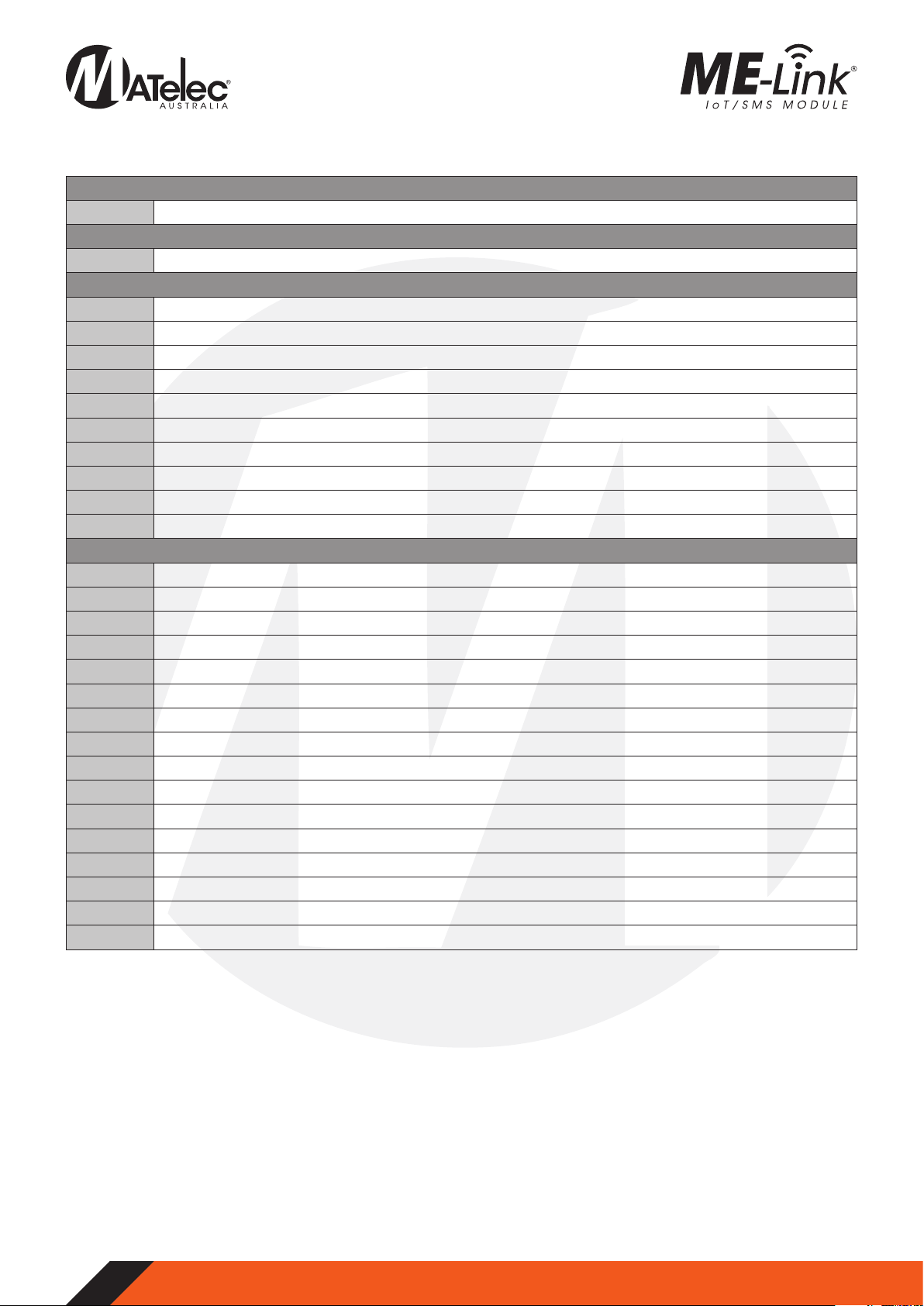
Link Status Description Function Cause
Green Flashing, Red Off Network connected N/A
Green Flashing, Red 1 Flash Network connected, sending SMS N/A
Green Off, Red Solid Hardware fault Contact supplier for further assistance
Green Off, Red 1 Flash Connecting, searching for mobile
network
Wait for network connection search to
finish
Green Off, Red 2 Flashes Network connection failed Check the SIM card is activate and
has credit
Green Off, Red 3 Flashes Network not found/ Poor signal
strength
Check antenna connection and
mobile signal at device.
Green Off, Red 4 Flashes Network connection denied
Check SIM is Telstra compatible and
SIM is active and has credit (Only
Telstra networks are currently valid)
Green Off, Red 5 Flashes SMS failed to send Check that SIM is still installed, active
and has credit
Green Off, Red 6 Flashes SIM card not detected Install or reinstall Micro SIM card and
check installation orientation
Green Off, Red 7 Flashes SIM Pin is enabled Disable the SIM pin before retrying
connection
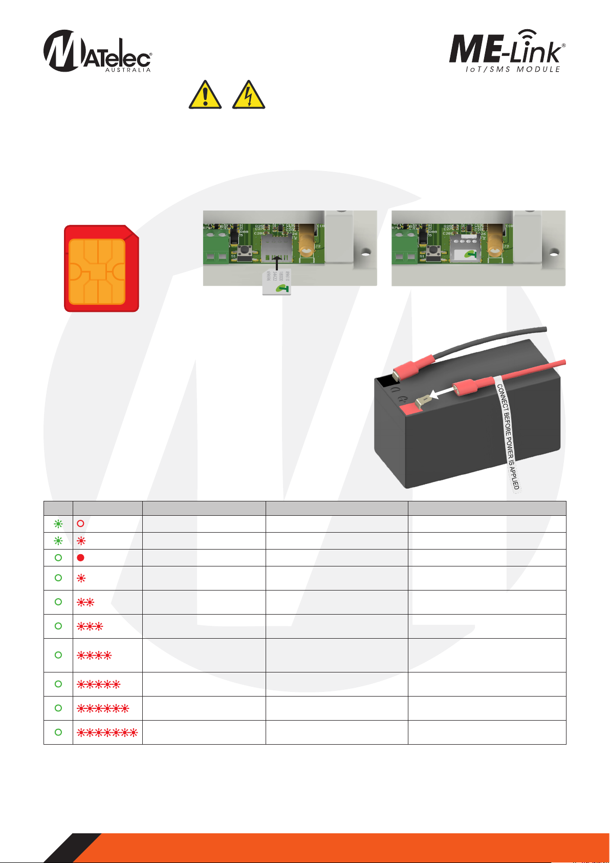
3.1 - SIM Card Installation
The SMS alarm sender takes a Micro SIM card which must be from a network operator who offers the CAT-M1 700Mhz frequency. At
the time of printing all SIM cards that use the Telstra network will be compatible. Other network providers will be compatible when
they support CAT-M1 modules.
1. Ensure power to the panel is OFF.
2. Firstly, ensure that the SIM card is activated with credit and ready to send text messages.Also,ensure that the SIM PIN is disabled.
3. Insert the SIM card with the chip gold plate facing down and the missing corner to be inserted in first. See pictures below.
4. The SIM needs to be pushed in firmly. Ensure that it fits properly in the SIM holder.
Micro SIM card required
12mm
15mm
Install SIM card with gold chip facing
down and missing corner first
Ensure SIM card is pressed in firmly and fits
properly in the SIM holder
3.2 - Enable Battery Backup
To have the SMS alarm sender operating when power fails,the internal battery
must be connected. With power isolated, connect the loose wire near the
battery labelled ‘CONNECT BEFORE POWER IS APPLIED’. See image to the right.
If power is to be isolated for more than 7 days ensure this wire is disconnected
to prevent the battery going flat.
3.3 - Testing Mobile Connection
The SMS alarm sender is tested and programmed by sending SMS messages
to the SIM card’s phone number.
1. Check the SMS controller’s indicator lights to ensure that power is on and
sim card is connected to mobile network. If there is no reply, check the
indicator lights status table below: