Mateng EF95 User manual

1
FOREWORD
The purpose of this manual is to assist you in operating and maintaining your
Flail mower. Read it carefully before operating and maintaining the Flail mower, it
furnishes the specifications, construction, instructions and also the maintenance.
Some information may be general in nature due to unknown and varying
conditions. However, through experience and these instructions, you should be
able to develop operating procedures suitable to your particular situation.
“Right” and “left” as used throughout this manual are determined by facing the
direction the machine will travel when in use.
Please kindly note that the contents of this operations manual may be a little bit
different from the Flail mower that you actually purchase. This is due to the
continuous improvement and development of the series Flail mower, however,
the specifications and structure of the Flail mower shall be subject to change
without notice.
Thank you very much for purchasing our products. We cordially welcome all the
suggestions, advises and comments on our products from the users and dealers
so that we may make necessary improvements on our products continuously to
meet the requirements of every specific market.
We strived to make this operations manual as correct as possible. However, we
do not guarantee the accuracy or recentness of the information herein due to
having translated the manual to English. We assume no liability for errors or
omission.

2
CONTENTS
CHAPTER ⅠSAFETY INFORMATION ...............................................................................3
1.1 Safety First ..............................................................................................................3
1.2 Safety Signs ............................................................................................................4
CHAPTER ⅡSPECIFICATIONS .........................................................................................5
2.1 Brief Introduction .....................................................................................................5
2.2 Specifications and Parameters for Flail Mower........................................................6
CHAPTER ⅢOPERATION.................................................................................................7
3.1 Checking Before Operating .....................................................................................7
3.2 Adjusting the Height.................................................................................................8
3.3 Regulating the Tension of Driving Belt.....................................................................9
3.4 Staring up ................................................................................................................9
CHAPTER ⅣSERVICE AND MAINTENANCE..................................................................11
4.1 Service...................................................................................................................11
4.2 Maintenance..........................................................................................................12
4.3 Storage..................................................................................................................13
4.4 Operation After Storage.........................................................................................14
CHAPTER ⅤILLUSTRATED PARTS CATALOGUE..........................................................15
5.1 Flail Mower Assembly (EF95-EF155) ....................................................................15
5.2 Gearbox assembly (EF95-EF155).........................................................................17
5.3 Blade Axle and Transmission Parts (EF95-EF155)................................................18
5.4 Flail Mower Assembly(EF165-175)........................................................................19
5.5 Gearbox assembly(EF165-175).............................................................................21
5.6 Blade Axle and Transmission Parts(EF165-175) ...................................................22

3
CHAPTER ⅠSAFETY INFORMATION
PLEASE NOTE
Make sure all potential operators of this equipment review this manual and
all safety messages contained within.
1.1 Safety First
Read this service manual before using the machine.
This safety alert symbol indicates important safety messages in this
manual. When you see this symbol, carefully read this message that
follows and be alert to the possibility of personal injury or death.
This machine is designed for pulverizing grass and short bramble, and shall be used in the
indicated purpose. You take the responsibility if the machine is used in any other purposes.
For safety of personnel and good performance of the machine, you shall check the
performance of the machine and the tractor before starting the machine.
All persons and animals shall keep away the machine when you start it.
The operator shall not put on too loose clothes during operating the machine.
Do not touch the rotor when the machine rotates.
Keep away the machine when it moves.
When the tractor and the machine are moving on the road, always keep the machine off.
Before repairing the machine, stop all movable parts and the tractor, keep the key with
yourself.
Always keep the machine in a good state, if necessary, repair or change the defective parts.
Don’t use the machine to transport personnel.
Don’t modify the machine.

4
Pay attention to the sharp and pointed parts during repairing the machine.
All protective parts shall be guaranteed to be in good state before starting the machine.
Don’t leave the tractor when moving the machine; and always take away the key of the
tractor with you.
The machine shall be operated in the recommended speed.
Don’t stay between the tractor and the machine.
Don’t start the machine in a closed place (due to the smoke from the tractor).
1.2 Safety Signs
1.2.1 Care of Safety Signs
1. Keep safety signs clean and legible at all times.
2. Replace safety signs that are missing or have become illegible.
3. If a component with a safety sign(s) affixed is replaced with a new part, make sure new
safety sign(s) are attached in the same locations as the replaced components.
4. Safety signs are available from your authorized Distributor or Dealer Parts Department or the
factory.
1.2.2 Safety Signs locations
The types of safety signs and locations on the equipment are shown in the illustrations that
follow. Good safety requires that you familiarize yourself with the various safety signs, the
type of warning and the area, or particular function related to that area, that requires your
SAFETY AWARENESS.

5
CHAPTER ⅡSPECIFICATIONS
2.1 Brief Introduction
The series Flail mower is designed for pulverizing grass and short bramble, and shall be
used in the indicated purpose.
The Flail mower consists of a rotating shaft with many blades attached to it. The blades cut
the grass while traveling over the working area. Rotational power to the shaft is provided by
the tractor PTO through the gearbox in the center of the machine.
The Flail mower attaches to the 3 point hitch on the tractor.
Fig. 2.1 Main components of the Flail mower
1. Blade axle 2. Blade axle cover 3. Combined fender 4.Supporting frame
5. Gearbox assembly 6. Suspension bracket 7. Transmission shaft 8. Belt wheel and belt

6
2.2 Specifications and Parameters for Flail Mower
Model EF95 EF105 EF115
Dimensions (L×W×H) (mm) 1050×687×722 1150×687×722 1250×687×722
Structure weight (kg) 115 130 145
Cutting width (mm) 929 1029 1129
Working efficiency (m2/h) 2500-7500 3000-8000 3300-9000
Input rotating speed (RPM) 540
PTO spline size 6-tooth Φ35mm Rectangular spline
Power required (HP) 16-20 20-30 20-30
Model EF125 EF135 EF145
Dimensions (L×W×H) (mm) 1350×687×722 1450×687×722 1550×687×722
Structure weight (kg) 160 175 190
Cutting width (mm) 1229 1329 1429
Working efficiency (m2/h) 3700-9800 4000-10600 4300-11400
Input rotating speed (RPM) 540
PTO spline size 6-tooth Φ35 mm Rectangular spline
Power required (HP) 20-35 25-35 25-35
Model EF155 EF165 EF175
Dimensions (L×W×H) (mm) 1650×687×722 1750×687×722 1850×687×722
Structure weight (kg) 210 235 255
Cutting width (mm) 1529 1629 1729
Working efficiency (m2/h) 4600-12240 4900-13000 5200-13800
Input rotating speed (RPM) 540
PTO spline size 6-tooth Φ35 mm Rectangular spline
Power required (HP) 30-40 30-40 30-40

7
CHAPTER ⅢOPERATION
CAUTION: Be familiar with the machine before starting. Read
this manual carefully to learn how to operate the
machine safely and how to set it to provide
maximum field efficiency.
3.1 Checking Before Operating
ATTENTION: Only use universal joint conforming to CE
standard and protect them properly.
Before operating the machine, the following areas should be checked off:
1. Before starting up the machine, check and Lubricate all grease points, all lubricated
parts inside the machine.
2. Use only an agricultural tractor of horsepower within limits of the machine specified.
3. Check that the machine is properly attached to the tractor. Be sure retainers are used
on the mounting pins.
4. Be sure extra weights are mounted on the front of the tractor.
5. Check the oil level in the gearbox. Add as required.
6. Check that the tractor PTO shaft turns freely and that the machine driving shaft can
telescope easily.
7. Check the blades. Be sure they are not damaged or broken and swing freely in their
mount. Repair or replace as required.
8. Check and tighten the blade bolts.
9. Check for entangled material in all rotating parts. Remove this material.
10. Install and secure all guards, doors and covers before starting.
11. Before installing the universal joint, the tractor and the machine motor shall be
stopped and the key be taken away. The universal joints shall be installed in good
state, with proper protective parts.
12. The chain on the protective parts of the universal joint shall be guaranteed in good
condition, in case, automatic rotation occurs.
13. All other persons shall leave the ground before connecting the driving power from the
8
tractor. Keep the output of the tractor at 540 RPM.
14. Before cleaning, repairing and lubricating the machine, stop the motor and take away
the key with you.
15. When the universal joint is not connected with the tractor, they must be connected
again through the frame to protect the joint from damaging.
16. Don’t approach the machine when the machine runs.
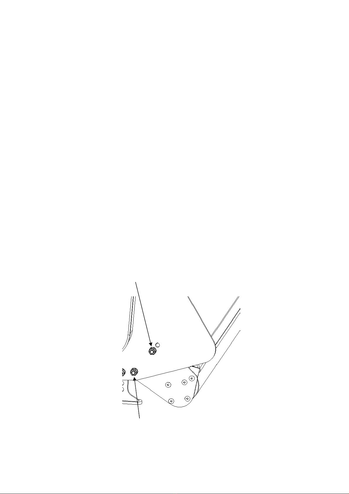
3.2 Adjusting the Height
In order to conduct a precise work, the machine shall be operated according to the
recommended cutting height.
For saving fuel and power, and reducing the wear of the machine, the cutting height must be
regulated correctly.
When regulating the working height, loosen the screw (1), remove the screws (2) on both
sides; regulate the roller height (see following drawing); fix the parts on the set position. The
lowest hole is the highest working height; put the screws (2) into the set hole; tighten screw
(1) and screws (2).
2
1

9
3.3 Regulating the Tension of Driving Belt
ATTENTION: The machine shall always stand still for
regulating the tension.
Remove the drivng betl cover. Loosen screws 1 2 3 4. and adjust screw 1. Tighten the
screws 1 2 3 4 . Put back the driving belt cover.
1
2 3 4
3.4 Staring up
Before starting the machine, control and adjust the following items:
zTension of trapezoidal driving belt.
zOil level of gear.
zPoint of lubrication
zAll bolts, nuts and screws.
This manual suits for next models
8
Table of contents
Popular Farm Equipment manuals by other brands

Schaffert
Schaffert Rebounder Mounting instructions

Stocks AG
Stocks AG Fan Jet Pro Plus 65 Original Operating Manual and parts list

Cumberland
Cumberland Integra Feed-Link Installation and operation manual

BROWN
BROWN BDHP-1250 Owner's/operator's manual

Molon
Molon BCS operating instructions

Vaderstad
Vaderstad Rapid Series instructions


