Matest B041 User manual

O P E R A T I N G M A N U A L
Gyratory Compactor
M A N U A L C O D E
B041
DO NOT TRY TO OPERATE THIS APPLIANCE BEFORE READING
AND LEARNING THIS MANUAL IN ALL ITS PARTS
USERS:
MACHINE MANUFACTURERS / DRAUGHTSMEN
/ OPERATORS MAINTENANCE / WORKERS
REV.
DESCRIZIONE
REDATTO/GESTITO
APPROVATO
COD. IDENT.
PAGINE
DATA EMIS.
0
6
Manuale Istruzioni
GN
UTEC
B041
.M01.
EN
48
07
/201
4

Rev. Descrizione Redatto/Gestito Approvato Cod.Ident. Pagine Data Em.
0.6 Manuale Istruzioni GN UTEC B041.M01.EN 2/47 07/2014
GENERAL INDEX
Chapter
1
GENERAL INFORMATION
1.1
Warnings
1.8
Machine Identification Data
1.2
WARNING and DANGER indications - SIGNS
1.9
EC Stamp
1.3
Aim of the Instructions Manual
1.10
Usage
1.4
Structure of the Instructions Manual
1.11
Operators
1.5
Composition of the Instructions Manual
1.12
Storage
1.6
Modifications and enclosures of the Instructions Manual
1.13
Transportation and Movement
1.7
Constructor Identification
1.14
Packaging removal
Chapter
2
TECHNICAL CHARACTERISTICS
2.1
General machine description
2.2
Dimension and weight
2.3
Electrical supply
2.4
Noise
Chapter
3
GENERAL SAFETY NORMS
3.1
General norms
3.2
Machine Safety devices and protection
3.3
Passive safety devices
3.4
Active safety devices
Chapter
4
INSTALLATION INSTRUCTIONS
4.1
Location
4.2
Handling and movement
4.3
Assembling procedure
4.4
Electrical connection
4.5
Pneumatic connection
Chapter
5
MAN
-
COMMAND INTERFACE
5.1
Workplace
5.2
Commands and signals
5.3
Meters – Indicators
5.4
How to operate
Chapter
6
MACHINE
REGULATION AND TUNING
6.1
Regulations
6.2
Checking the safety devices work
Chapter
7
IN FUNCTION
-
USE
7.1
Machine calibration – Meters - Indicators
7.2
Switching on the equipment
7.3
Equipping – Sample positioning
7.4
Regulation
7.5
Switching the appliance on
7.6
Normal stop
7.7
Emergency stop
7.8
Start up after emergency
7.9
Stop commanded by Safety circuit
7.
10
Start up after stop commanded by Safety circuit
7.
11
Switching off
7.
12
Test Start Up
7.
13
EXAMPLE OF OPERATING
Chapter
8
MAINTENANCE
8.1
Periodical checks
8.2
Ordinary Maintenance
8.3
Extraordinary Maintenance
8.4
Authorised maintenance centres
Chapter
9
GUIDE TO RECOGNISING DAMAGE AND ANOMALIES
Chapter
10
SPARE PARTS
Chapter
11
INACTIVITY
Chapter
12
DECOMMISSIONING THE MACHINE
Annexes
I
PNEUMATIC SYSTEM DIAGRAMS
II
WIRING DIAGRAMS
III
ACCESSORY
Rev. Descrizione Redatto/Gestito Approvato Cod.Ident. Pagine Data Em.
0.6 Manuale Istruzioni GN UTEC B041.M01.EN 3/47 07/2014
Chapter
1
GENERAL INFORMATION
1.01
WARNINGS
The manufacturer does not accept any responsibility for direct or indirect damage to people, things or animals and use of the
appliance in different conditions from those foreseen.
The manufacturer reserves the right to make changes to the documentary information or to the appliance without advance
notice.
Check the machine responds to the standards in force in the state in which it has been installed.
All operations necessary for maintaining machine efficiency before and throughout use are the operator’s responsibility
Carefully read the entire manual before operating the machine.
It is vital to know the information and limitations contained in this manual for correct machine use by the operator.
Interventions are only permitted if the operator is accordingly competent and trained.
The operator must be knowledgeable about machine operations and mechanisms.
The purchaser must ensure that operators are trained and aware of all the information and clarifications in the supplied
documentation. Even with such certainty the operator or user must be informed and therefore aware of potential risks when
operating the machine. Safety, reliability and optimum performance is guaranteed when using original parts.
Any tampering or modifying of the appliance (electrical, mechanical or other) which has not been previously authorised in
writing by the manufacturer is considered abusive and disclaims the constructor from any responsibility for any resulting
damage. All necessary operations to maintain the efficiency of the machine before and throughout use are the responsibility of
the user.
1
.02
WARNING AND DANGER INDICATIONS
-
SIGNS
The machine has been designed and constructed according to the current norms and consequently with mechanical and
electrical safety devices designed to protect the operator or user from possible physical damage. Residual risks during use or
in some intervention procedures on the device are however present. Such risks can be reduced by carefully following manual
procedures, using the suggested individual protection devices and respecting the legal and safety norms in force.
This manual includes “Warning” and “Danger” indications in relevant chapters. These indications are shown with the words
“Danger” or “Warning” in bold font and uppercase to make them highly visible.
WARNING
Il simbolo viene impiegato per indicare che la non osservanza delle indicazioni prescritte
potrebbe causare “Danno allo strumento”.
DANGER
Il simbolo viene impiegato per indicare che la non osservanza delle indicazioni prescritte
potrebbe causare “Danno allo strumento e/o infortunio al personale”.
INSTRUCTIONS
indicates the need to consult other documents before performing
operations.
“DANGEROUS ZONE” indicates any zone inside or in the proximity of the appliance in which a person is exposed to the risk
of injury or damage to health.
1.03
AIM OF THE INSTRUCTIONS MANUAL
This manual has been edited with the aim of providing all machine operators with all the necessary information on
installation, use and maintenance from production to scrapping in as comprehensive and clear manner as
possible.All the procedures useful for any foreseeable emergency situations have been listed by the manufacturer
and can be verified during use.
Operators, for whom this manual has been written, due to their competence must give instructions or operate the
machine themselves.The instructions manual must be carefully consulted by laboratory or site safety managers,
equipment operators and any internal and external maintenance workers.
The manual is integral to the product and refers to this appliance only.
The manual must be safeguarded and always kept near the equipment so that it can be easily consulted
whenever necessary.
IMPORTANT: The manual does not substitute the experience and technical training of the worker but must be
considered a guide for carrying out its functions.Furthermore all the norms and rules the operator should be
aware of or consult for correct use of the machine and/or test performance can be found in the manual.
This responsibility is entrusted to the installer and Laboratory or Site Manager where the machine is installed.
The Constructor is available to provide further informati.
1.04
STRUCTURE OF THE INSTRUCTIONS MANUAL
The manual can consist of a number of documents, as shown in the appropriate list.
Verify that all documents are present; otherwise request the missing parts from the Constructor before using the
machine.Instructions can be supplied with enclosures containing diagrams and designs, which are necessary for
interpretation of correct machine use and maintenance.
1.05
COMPOSITION OF THE INSTRUCTIONS
MANUAL
Description document
Instruction manual code
INSTRUCTIONS MANUAL
B041.M01

Rev. Descrizione Redatto/Gestito Approvato Cod.Ident. Pagine Data Em.
0.6 Manuale Istruzioni GN UTEC B041.M01.EN 4/47 07/2014
1.06
MODIFICATIONS AND ENCLOSURES OF THE INSTRUCTIONS MANUAL
Il This manual reflects the state at the time of the launch of the machine on its market. If any modifications, improvements or
adjustments have been made since machine supply the Manufacturer does not have to intervene on the marketed machine
and will not consider the machine or the manual deficient or inadequate.
1.07
CONSTRUCTOR IDENTIFICATION
See the front page headline
1.08
MACHINE IDENTIFICATION DATA
On the identification nameplate of the machine are reported the
identification data and the electrical characteristics.
1.09
EC STAMP
SEE EC DECLARATION
1.10
USAGE
Machine or instrument usage:
This Gyratory Compactoris used to simulate and reproduce the real compaction conditions under actual road
paving operations, hence determining the compaction properties of the asphalt. Such compaction is achieved by
combining the rotary action and the vertical resultant force applied by a mechanical head.
Appropriate uses: Those defined in standard
( UNI EN 12697-10, UNI EN 12697-31 / ASTM D6925 / AASHTO T312).
This appliance is for the exclusive use which it has been conceived for. Any other use is considered improper and
therefore negligent. Machine use is allowed only in places free from danger of explosion or fire.
During operation check for conditions of danger.Immediately stop the machine should it be working irregularly,
and consult the authorised dealer’s Sales Service department. It is the Client’s responsibility to verify at the time
of installation and use that no conditions of use arise which are different to those indicated. Refer to the
Constructor when in doubt.
1.11
OPERATORS
DANGER
WARNING
The use, transportation, installation, maintenance, demolition and disposal of the
appliance are only permitted to “QUALIFIED PERSONNEL”. This
manual is exclusively aimed at “QUALIFIED PERSONNEL” and contains the
necessary information for machine use.
”QUALIFIED PERSONNEL” means people who, due to their training, experience and education, as well as
knowledge of the relevant standards, limitations and measures, have been authorised by the “PLANT SAFETY
MANAGER” to carry out any necessary activity and are able to recognise and avoid any possible danger.
The manufacturer recommends that the instructions, procedures and recommendations in this manual and the
work safety legislation in force be scrupulously adhered to, even with the use of appropriate protection devices
(whether individual or part of the machine).
Knowledge and respect of the instructions, safety warnings and danger in this manual are all necessary for
installation, operation, management and machine maintenance with a minimal risk.
The “PLANT SAFETY MANAGER
” has the following responsibilities and duties:
- To know the machine functions, its commands, safety
and protection devices, possible dangers of use and all
the information in this manual in detail. This
knowledge can only be gleaned from detailed reading
of this manual.
- Correctly train and educate the “QUALIFIED
PERSONNEL” before allowing them access to the
machine. The personnel must also be exhaustively
trained with regards to the machine’s protection
devices.
- To know the safety legislation in force in detail in
order to operate the machine
- To recognise the “QUALIFIED PERSONNEL” for
transportation, handling, installation, use, maintenance,
disposal, etc.
- Ensure the machine’s safety devices are not
tampered with or removed and are checked on a daily
basis. Provide the operator appropriate individual
protection devices according to the laws in force.
- The constructor is available for clarification, assistance and training and declines all responsibility for damage to
things or people resulting from improper, incorrect and negligent use by untrained personnel.
Rev. Descrizione Redatto/Gestito Approvato Cod.Ident. Pagine Data Em.
0.6 Manuale Istruzioni GN UTEC B041.M01.EN 5/47 07/2014
1.12
STORAGE
WARNING
The appliance must be stored and conserved in the original packaging and in a closed
environment, protected from atmospheric agents with a minimum temperature of -15C°, and a
maximum of +60C°and a maximum humidity of 70%.
1.13
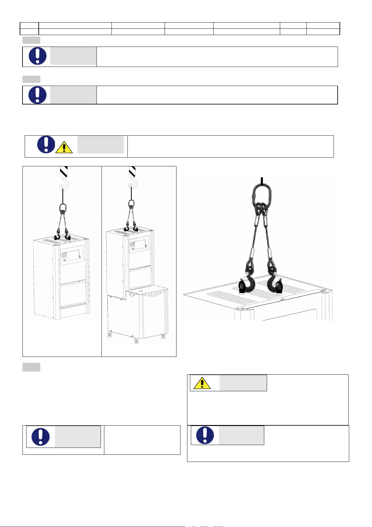
TRANSPORTATION AND MOVEMENT
WARNING
In order to avoid irreparable machine damage, move with care, do not overturn, protect from
rain, do not stack, protect the packaging and its contents from bumps and sources of heat.
Machine transportation and movement must be entrusted to Qualified Personnel who can ensure correct
movement.
The machine is equipped of two steel eyebolts. (top side).
DANGER
WARNING
Do not transport or move the product should it be impossible to respect
the conditions on the packaging or there be any doubts. Request
information from the constructor.
260 Kg 350 Kg
1.14
PACKAGING REMOVAL
After removing the packaging check the machine is
complete and that there are no visibly damaged parts.
DO NOT USE THE MACHINE and refer to the
constructor when in doubt.
DANGER
The components used for
packaging (plastic bags,
polystyrene, nails, screws,
wood, etc)must
be kept out of reach of children, as they are sources of
danger. These components should be placed in the
appropriate containers.
WARNING
In order to avoid bumps
and overturn adopt the
normal and logical
precautions.
WARNING
Before disposing of the
packaging check all
machine components
such as accessories, utensils, instructions, documents
etc have been removed.

Rev. Descrizione Redatto/Gestito Approvato Cod.Ident. Pagine Data Em.
0.6 Manuale Istruzioni GN UTEC B041.M01.EN 6/47 07/2014
Chapter
2
TECHNICAL
CHARACTERISTICS
2.01
GENERAL MACHINE DESCRIPTION
This Gyratory Compactor, is used to simulate and reproduce the real
compaction conditions under actual road paving operations, hence
determining the compaction properties of the asphalt.
Such compaction is achieved by combining the rotary action and the vertical
resultant force applied by a mechanical head. The Compactor comprises a
highly rigid steel frame ensuring excellent angle control.
Load is applied by an electro-pneumatic cylinder, servo-controlled by a
precision pressure regulator; the height is measured by a linear transducer.
Gyratory motion is generated by an eccentric high precision system allowing
an easy set up with precision and constant angle of gyration.
The rotation speed is controlled by an inverter through on board computer
control. Using the proper perforated mould, the Compactor is able to run tests
also on cold emulsified asphalt mix.
The acquired results are also employed in the investigation of volumetric and
mechanical characteristics of the asphalt mix.
Picture.1
1
MAIN SWITCH
2
EMERGENCY
STOP
3 DISPLAY
4 USB / SD
5 SLIDING PANEL
6 TEST CHAMBER
7
REAR PANEL
8
AIR INTAKE
FITTING (pipe
Ø10)
9
ELECTRIC
POWER CABLE
Picture.2
ACCESSORIES
INSTRUCTIONS
Before the Assembly and use of the optional accessories,
please refer to the relevant instructions.
Hand operated specimen
Integrated worktop
Mechanical automatic specimen extruder
extruder

Rev. Descrizione Redatto/Gestito Approvato Cod.Ident. Pagine Data Em.
0.6 Manuale Istruzioni GN UTEC B041.M01.EN 7/47 07/2014
LAYOUT :
Gyratory Compactor +
Integrated worktop + Extruder
Fig. 3
MOLD (accessory required for the
execution of the test)
1
MOLD BODY
2
RING OF ARREST
3
BOTTOM
There are different types. See for commercial catalogs
and specific encodings.
Two types of pistons
are available
(accessory necessary
for the execution of
the test) which differ
in the type of fixing.
The nominal diameter
must be chosen
according to the size
of the mold. Check the
catalog and find all
the specific
codes..
PISTON type 1
Fig. 4
1
PISTON
2
CLAMPING SCREWS
PISTON type 2
Fig.
1
PISTON
2
SCREW
3
TOOTH

Rev. Descrizione Redatto/Gestito Approvato Cod.Ident. Pagine Data Em.
0.6 Manuale Istruzioni GN UTEC B041.M01.EN 8/47 07/2014
HARDWARE:
The main hardware features of the machine’s mother
board are described as follows.
ATTENTION
Even if designed and potentially available, some features
could be not be present on the control unit box.
•312 MHz processor that can be expanded up to 806 MHz.
•64 MB RAM that can be expanded up to 128 MB.
•32 MB flash memory that can be expanded up to 256 MB.
•LCD TFT QVGA (320x240 pixel) touch-screen.
•Keyboard with 5 crosswise keys.
•One audio channel.
•Buzzer.
•Clock.
•8 digital outputs.
•8 digital inputs.
•1 analog output (16 bit - 65536 points).
•8 analog inputs (two of them at high performances).
•Ethernet 100 Mbit for PC connection.
•2 USB-Host (to connect mouse/keyboard/pen drive).
•1 USB-Client.
•Slot SD-Card.
•1 RS232.
•1 RS485.
•2 controllers for step motors.
•Expansion slot for additional analog inputs.
•Expansion slot for motors control.
MAIN FEATURES:
•Gyratory angle: adjustable from 0 to 2,4°
•Gyration rate: adjustable from 5 to 60 work cycles/min
•Compacted specimen size: dia 100 and 150 mm; height
from 0 to 200 mm for both sizes.
•Vertical load on 150mm dia specimen: adjustable from 10 to
900 kPa
•Vertical load on 100 mm dia specimen: adjustable from 23
to 1500 kPa SOFTWARE:
The main software features of the machine’s mother board
are listed as follows
•Operating system: “Windows Embedded CE 6.0 R2”.
•More intuitive interface and a simplified management of
the machine (start up of the test with few and simple
commands).
•More opportunities for calculations and graphic
visualization (graphs on the machine and printing of the
results in a graphic mode).
•More opportunities for languages and International format
management (date and time, decimal separator, unit of
measurement…).
•Modular structure of the software in order to allow the
installation of new test modules later.
•The software on the machine can be easily updated.
•An unlimited memory provided by the SD-Card and USB-
Host slots.
Possibility to connect the machine to Internet in order to
activate the remote checking functions.
2.02
DIMENSION AND WEIGHT
A LENGTH
640 mm
B WIDTH
500 mm
H HEIGHT
1060mm
WEIGHT
250Kg
2.03
ELECTRICAL SUPPLY
On the identification
nameplate of the machine
are reported the
identification data and the
electrical characteristics.
Power supply:
230V
1ph
50/60Hz
1000W
Picture
. 5
2.04
NOISE
The air noise emission levels shown do not necessarily imply the levels of exposure to the worker.
The levels of exposure to the operator are obviously linked to the emission levels of the appliance; however other factors
influence the levels of exposure to the operator: length of exposure, environmental characteristics, the presence of other
machines etc. The appliance emission levels allow anyway an estimate to be carried out on the dangers due to noise.
If the daily personal exposure is equal to or more than 85 dB (A) it is advisable to use the Individual Protection Devices
(protective headphones, plugs, etc.). If the daily personal exposure is equal to or more than 90 dB (A) it is compulsory to use
Individual Protection Devices (protective headphones, plugs, etc.). For further information consult the standards in force in the
country of installation.

Rev. Descrizione Redatto/Gestito Approvato Cod.Ident. Pagine Data Em.
0.6 Manuale Istruzioni GN UTEC B041.M01.EN 9/47 07/2014
DANGER
Continuous use of the appliance and machines predictably present in the
installation environment could cause a heightened daily personal exposure to
noise.
Chapter
3
GENERAL SAFETY STANDARDS
3.01
GENERAL STANDARDS
To ensure the safety of machine operators:
· Any tampering with the appliance not pre-
emptively authorised by the manufacturer exempts
the manufacturer from any responsibility for
damage caused by or to it.
·The removal or tampering with safety devices
entails a violation of the safety standards.
· Machine use is only allowed in areas where
there is no risk of explosions or fires.
· Only the original fittings can be used. The use of
unoriginal fittings exonerates the manufacturer from
all responsibility.
• Check the appliance is in ideal working conditions
and that its parts are not worn or faulty before
Carry out all necessary maintenance
• Do not wear loose clothing, ties, chains or
anything else which could become caught in the
frame or other moving parts of the appliance.
• Be aware of the danger of electrical shocks from direct
or indirect contact due to unforeseen electrical faults.
• Do not subject the appliance to violent impact.
• Do not expose the appliance to fire, welding sparks or
extreme temperatures.
• Do not bring the appliance into contact with corrosive
substances.
• Do not wash the appliance with jets of water.
Check the workspace around the machine is clear from
potentially dangerous objects.
The machine operator must wear appropriate work
clothing such as protective glasses, gloves and mask in
order to avoid damage from, for example, harmful dust
projection. Wear a lower back support when lifting heavy
parts.
There should be no hanging objects such as bracelets
or otherwise, long hair should be protected with relevant
precautions, shoes must be appropriate for the type of
operation to be carried out.
DURING USE
When operating check there are no
conditions of danger. Immediately stop the
machine when it is functioning irregularly.
Contact the authorised Sales Service
department.
• For the operator’s safety do not touch any
part of the appliance when testing and use
the appropriate individual protection devices
in order to keep the operator safe.
RISK OR DANGER
PROTECTION DEVICES
FINGER
SQUEEZE
CUTS OR
ABRASIONS
REINFORCED
GLOVES
MATERIAL
FALL
ACCIDENT-
PREVENTION
SHOES
3.02
MACHINE SAFETY DEVICES
AND PROTECTION
DEFINITION: Protections are all the safety measures that consist of the use of
specific technical means (repairs, safety devices) to protect people from dangers
which cannot be limited reasonably in design.
DANGER
Tampering with the protections or any appliance
modification could cause risks to users or other
exposed people.
The manufacturer does not assume any responsibility for direct or in direct damage
to people, things or animals following tampering with the protections.
3.03
PASSIVE SAFETY DEVICES
Passive safety devices are the devices or solutions which eliminate or reduce the
risks to the operator without any active intervention by the operator.
The machine has got a protection door ,which prevents the opening during the test
so that the operator cannot come in touch either with the internal mechanisms .The
door opening causes an immediate interruption of the power feeding; in this way the
motor and the road wheel stop moving. The rotation can start again only after the
Picture
. 6
Rev. Descrizione Redatto/Gestito Approvato Cod.Ident. Pagine Data Em.
0.6 Manuale Istruzioni GN UTEC B041.M01.EN 10/47 07/2014
closing of the protection door.
3.04
ACTIVE SAFETY DEVICES
Active safety devices are the devices or solutions which eliminate or reduce the
risks to the operator and require active and conscious intervention by the operator
for the preventive action to be carried out.
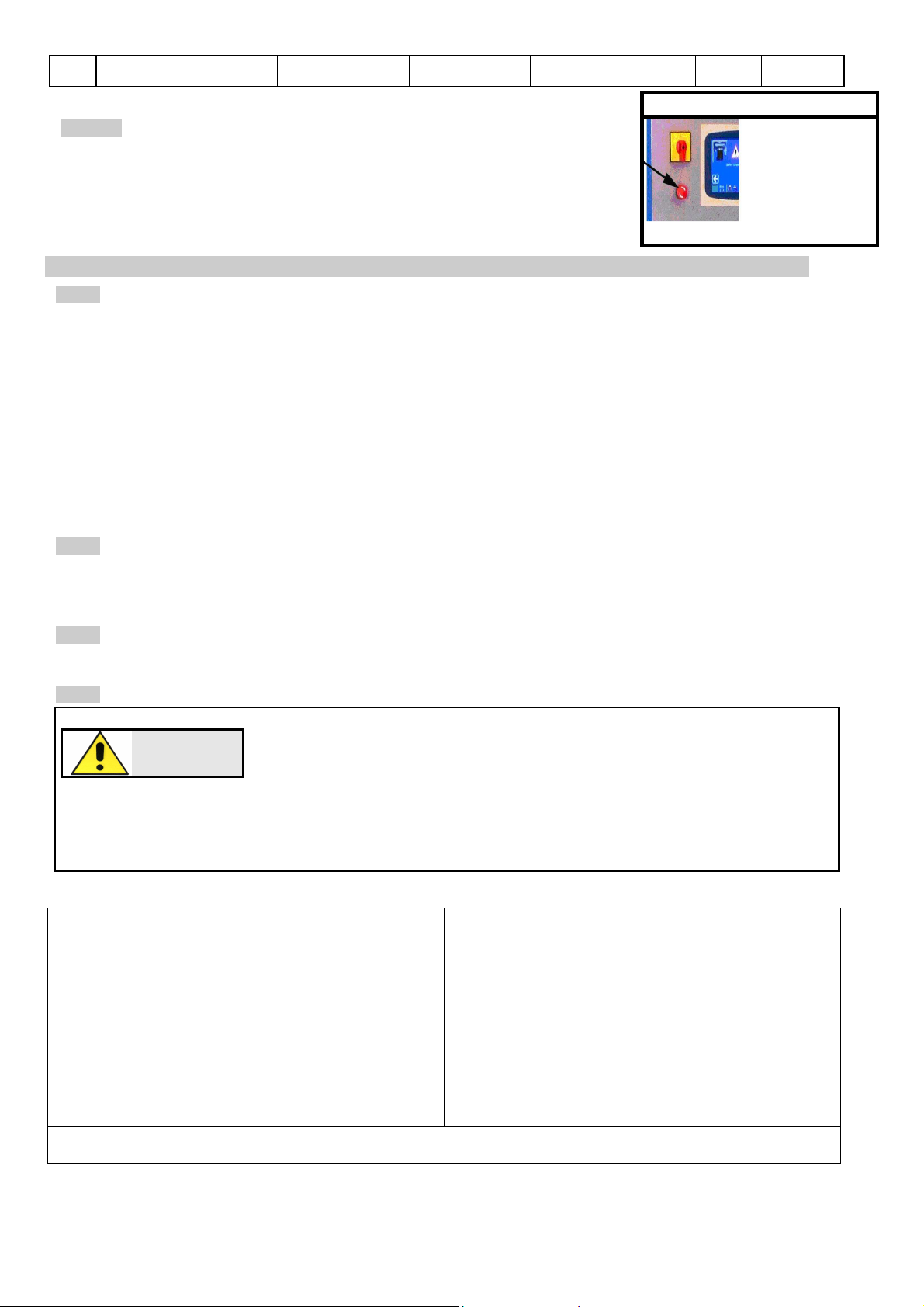
The appliance is equipped with a main switch acting also as emergency switch. By
activating it (Fig.7), stops moving.
Picture
. 7
Chapter
4
INSTALLATION INSTRUCTIONS
4.01
LOCATION
The equipment must be placed in an ideal position and environment for the use it has been conceived for
(laboratory use and protected from atmospheric agents) and that the machine is placed by a qualified operator.
ALLOWED TEMPERATURE:
+5°C / +40°C
ALLOWED RELATIVE HUMIDITY:
30% / 70%
GENERAL ADVICE
•The machine must be installed in an area which allows ease of access to all parts so that maintenance
may be carried out.
•Unauthorised people and objects which could be potential sources of danger must not be permitted in the
area surrounding the machine.
Do not position the equipment near instruments or appliances which could produce vibrations.
EN Standad requires the machine to be rigidly mounted on a firm and level concrete base. The levelling foot
supplied are considered acceptable for mounting on any firm and rigid level surface
4.02
TRANSPORTATION AND MOVEMENT
These instructions are applicable to the machine assemblers. Ensure the equipment is correctly supported at the
lifting point and that the machine does not slip. Do not remain in direct line with the application of force and do not
allow personnel where there are loads that cannot be adequately supported by mechanical means.
4.03
ASSEMBLING PROCEDURE
After removing the package, check that any parts of the machine are not damaged. In case of doubt, DO NOT
USE THE MACHINEand ask the manufacturer.
4.04
ELECTRICAL CONNECTION
DANGER
Wiring of the electrical system must be carried out by qualified personnel.
Before wiring consult the electric plan linked to the instructions manual and the
registration plate on the machine for information regarding supply, frequency and
nominal current. Connect the earthing system via the PE terminal (yellow-green)
before any other connection.
Apply a knife switch at the top of the connecting cable of the machine to the power system.
The knife switch must be combined with a safety device against the overload with a differential switch (safety
switch).The technical features of
the safety device must be in accordance with the standards in force in the
country where the machine has been installed.
ELECTRIC TOLERANCES:
•
Real voltage
±
10 % of the nominal one
•Frequency: ±1 % of the nominal one
in a continuous way
±2 % of the nominal one for a short period
•The harmonic distortion of the sum from the second
to the fifth harmonics not more than 10 % of the total
voltage as a real value between the conductors. A
further distortion of 2% is accepted for the sum from
the sixth to the thirtieth harmonics of the real total
value between the conductors.
•With reference to the voltage imbalance of the three-
phase voltage, the inverted sequence component and
the zero sequence component must not be more than
2% of the direct sequence component of the voltage.
•
The voltage pulses must not last more than 1,5 ms
with an up/down time between 500 ms and 500 ms
and a peak value not higher than 200 % of the real
value of the nominal tension.
•The electric supply must not be interrupted or
zeroed for more than 3 ms at any time. Between
two interruptions it must not take more than 1 s.
•The interruptions must not overcome 20 % of the
tension peak for more than one cycle. Between two
interruptions it must not take more than 1 s.
The manufacturer assumes no liability for any damages to people, things and animals caused by the non-
compliance of the above instructions.

Rev. Descrizione Redatto/Gestito Approvato Cod.Ident. Pagine Data Em.
0.6 Manuale Istruzioni GN UTEC B041.M01.EN 11/47 07/2014
4.05
PNEUMATIC CONNECTION
Connect the Compactor to compressed air system; the pipe must be connected to
the AIR INLET FITTING located at the back of the compactor (pipe outer diameter
10 mm).
Compressed air requirement:
50lt/min (
occasionally
)
Compressed air pressure:
7÷10 bar
Air Compressor
(Optional)
ATTENTION
It is essential to mount an
adequate maintenance unit, air
filter-regulator
(FR) upstream of the air input.
Indicative features:
working pressure:
0.05÷0.09 Mpa ;
filtration degree:
40 µm ;
air filter
regulator
(necessary
accessory)
ATTENTION
Do not use a lubricator on the supply side of this product.
Chapter
5
MAN
–
COMMAND INTERFACE
5.01
WORKPLACE
The picture on the side shows the working area “3” where the
operator will be more frequently; it allows possibility to open the front
door to place moulds and to operate on the control panel and set test
parameters.
After placing the mould on the worktop “2” and closing the door, the
user must program test parameters by means of the control panel
“1” and start the machine.During compacting action the user can
observe the specimen through the transparent panels and supervise
test data on the control unit touch screen display.
Fig. 8

Rev. Descrizione Redatto/Gestito Approvato Cod.Ident. Pagine Data Em.
0.6 Manuale Istruzioni GN UTEC B041.M01.EN 12/47 07/2014
5.02
COMMANDS AND SIGNALS
The man-machine interface pass
through the LCD TFT QVGA
(320x240 pixel) touch-screen
supported by a keyboard with 5
crosswise keys.All the machine
operating functions are
accessible through the touch-
screen and the keyboard as well.
Depending on the specific
contest the machine is working
in, some keys/functions can be
disabled or may assume a
particular meaning.
1 EMERGENCY
STOP BUTTON
2
MAIN SWITCH
3
DISPLAY
4
Keyboard
5
N°2 USB
-
Host
6
SLOT SD CARD
Consult the chapter related
to the screen you are
interested in to check the
exact use of the keyboard.
STRUCTURE OF THE SCREENS
1
Operating
area
It is the most important area of each screen
and it takes up the almost part of the display.
2
Status
Bar
It is divided into three parts and is placed in the
lower part of all screens. It provides with a
summary of the information concerning the
machine configuration and functioning.
Status Bar
Name and version of the machine
Status of the machine
Date and time
The central part is divided into four parts to highlight the following information:
Status of the machine
Alarm enabled or status
of the machine
It shows the presence
of one or more alarm
status ( ) ,or
configuration failure
( ) or the
operation status of the
machine
(following pages)
Configuration
profile
selected
State enabling legislation or active screen
State enabling legislation:
indicates whether the remote
execution is:
Enabled
disable
Screen enabled
:
It is represented by one of the following icons/pictures
to show the screen the operator is entering to. The list does not include
the icons that represent the Standards (see the relevant chapters). Some
screens can be entered only when using some specific machines
machine
calibration.
network
configuration.
password change.
software
maintenance.
visualization of the
enabled alarms.
configuration of the input analog channel
(the
icon also shows the number of the selected
channel).
configuration of the output
analog channel.
manual positioning.
calibration of the input analog channel
(
the icon
also shows the number of the
selected
channel)
.
calibration of the output
analog channel.
test archive
check of the input analog channel calibration
(the icon also shows the number of the
selected channel).
check of the output
analog channel
calibration
.
machine
configuration.
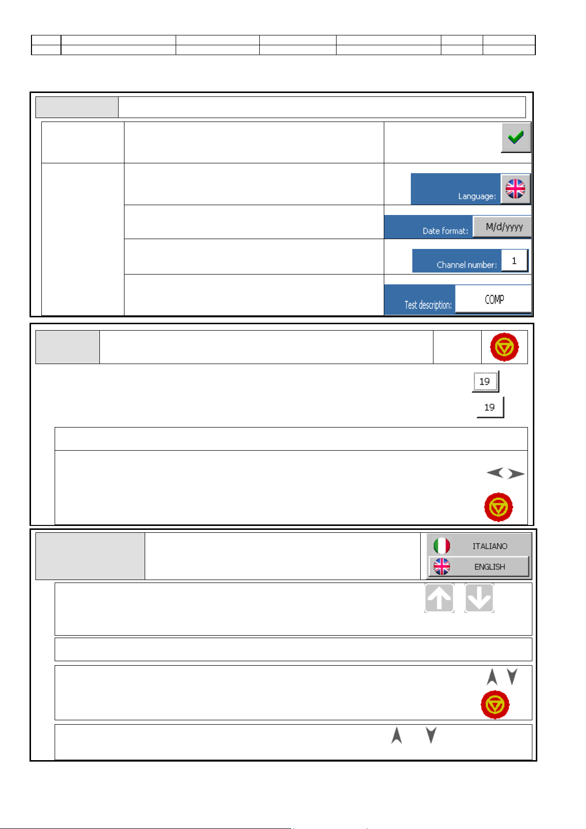
date and time set up.
International settings
.
Rev. Descrizione Redatto/Gestito Approvato Cod.Ident. Pagine Data Em.
0.6 Manuale Istruzioni GN UTEC B041.M01.EN 13/47 07/2014
MACHINE INTERACTION
BUTTONS:
All controls on the screens are shown as buttons and can be classified as follows:
:
1. command”
button:
Conceived for the execution of a machine function; this button
is usually shown on the right column of the operative area of
the display; on this button an image (such as the one shown
in the example) is visualized on a grey background Esempio:
2.“parameter”
button:”
This button is for the modification of a value through the
activation of a graphic scroll; an image on a grey background
is visualized on the button
Esempio:
This button is also for the modification of a value through the
activation of a text scroll; an alphanumeric text is visualized on
the button with a grey background
Esempio:
This button is also for the modification of a value through the
activation of a numeric scroll; a numeric text is visualized on
the button with a white background
Esempio:
.
This button is also for the modification of a value through the
activation of the virtual numeric/alphanumeric keyboards; a
numeric/alphanumeric text is visualized on the button with a
white background
Esempio:
FOCUS:
The Focus notion is used to point out which button of the screen will respond to
the pressure of the confirmation key
confirmation
key
A button has the focus active when it is visualized with dashed sides
example
A button has the focus inactive when it is visualized without dashed
example:
How to activate a button
through the touch-screen.
Touch the button and wait for the function execution (“command” button)
or for the change of the relevant value (“parameter” button).
How to activate a
button through the
keyboard.
Move the focus on the buttons visualized on the
screen (keys and ) up to the selection of the desired
button.
keys
Push the confirmation key and wait for the function
execution (“command” button) or for the change of
the relevant value (“parameter” button).
confirmation key
GRAFIC
SCROLL
It is visualized when a “parameter” button with an image on
a grey background has been activated. The below example
shows the graphic scroll for the language selection (screen
of the international settings).
How to select a graphic scroll
value with the touch-screen
Scroll the list up to the desired icon.
. ( or )
Touch the picture, wait for the closure of the scroll and for the update of
the relevant “parameter” button.
How to select a graphic scroll value
with the
touch-screen
Touch any point of the LCD display outside the scroll area
and wait for its closure.
How to select a value of a graphic
scroll with the keyboard
Select the desired image by skimming through
the list with keys. keys.
.
Push the confirmation key , wait for the closure
of the scroll and for the update of the relevant
“parameter” button.
confirmation
key
How to annul the selection of a value of a
graphic scroll with the keyboard
Push one of these keys, or and wait for the
closure of the scroll.

Rev. Descrizione Redatto/Gestito Approvato Cod.Ident. Pagine Data Em.
0.6 Manuale Istruzioni GN UTEC B041.M01.EN 14/47 07/2014
TEXT SCROLL
It is visualized when a “parameter” button with an
alphanumeric text on a grey background has been activated.
The below example shows the graphic scroll for the month
selection (screen of data and time setting).
How to select a value of the text
scroll with the touch screen
Scroll the list until the desired text is visualized. ( or )
Touch the desired text, wait for the closure of the scroll and for the update
of the relevant “parameter” button.
How to select a value of the text
scroll with the touch screen Touch any point of the LCD display outside the scroll area and wait
for its closure.
How to select a value of a text scroll
with the keyboard
Select the desired text by scrolling the list with
keys.
keys
Push the confirmation key , wait for the closure
of the scroll and for the update of the relevant
“parameter” button.
confirmation
key
How to annul the selection of a value of the
scroll with the keyboard Push one of these keys, or , and wait for the
scroll closure.
NUMERIC
SCROLL
It is visualized when a “parameter” button with a numeric value on a grey
background has been activated. The below example shows the graphic
scroll for the day selection (screen of data and time setting).
How to change the value of a numeric
scroll with the touch-screen
Decrease or increase the value until the desired
one is shown. ( oppure )
Touch the value (central area), wait for the scroll closure and for the update
of the relevant “parameter” button.
How to annul the change of the value of
a numeric scroll with the touch-screen
Touch any point of the LCD display outside the scroll area and wait for its
closure.
How to change the value of a numeric
scroll with the keyboard.
Decrease () or increase the value until the desired
one has been visualized. keys
.
Push the confirmation key, wait for the closure of the
scroll and for the update of the relevant “parameter”
button.
confirmation
key
How to annul the change of the value
of a numeric scroll with the keyboard.
Push one of these keys, or , and wait for the closure of the scroll.
VIRTUAL NUMERIC/ALPHANUMERIC
KEYBOARD
It is visualized when a “parameter” button with a numeric/alphanumeric
value on a white background has been activated.
Virtual numeric keyboard
Virtual alphanumeric keyboard
How to change
Insert the numeric/alphanumeric value using the virtual keyboard.
Rev. Descrizione Redatto/Gestito Approvato Cod.Ident. Pagine Data Em.
0.6 Manuale Istruzioni GN UTEC B041.M01.EN 15/47 07/2014
a
numeric/alphan
umeric value
with the virtual
keyboard. Touch / or push the confirmation key to confirm the new value; wait for
the closure of the virtual keyboard and for the update of the relevant “parameter” button.
How
to annul the change of a
numeric/alphanumeric value with the
virtual keyboard.
Touch and wait for the closure of the virtual keyboard.
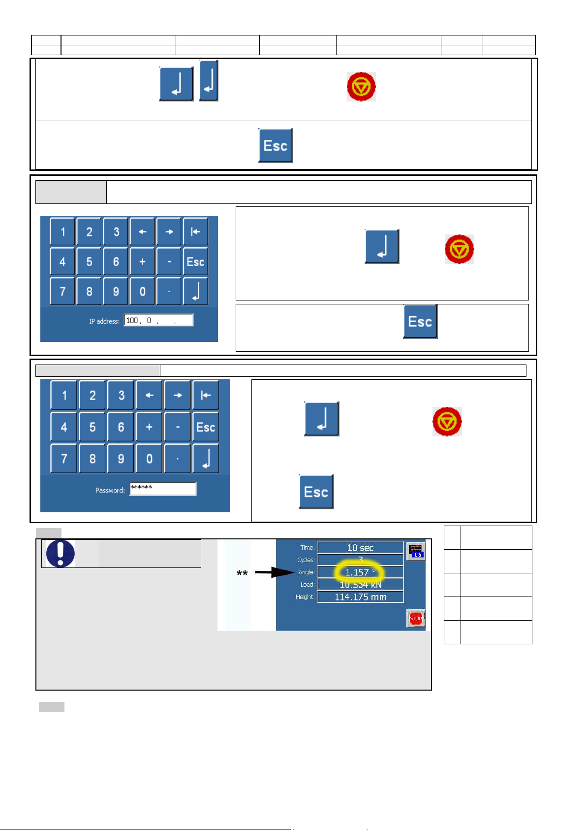
IP
ADDRESS
It is visualized when a “parameter” button is activated: the value is shown as an “IP address” on a white
background
How to change
an “IP
address” value
with the virtual
keyboard.
1. Insert the value as “IP address” using the
virtual keyboard.
2. Touch or press to confirm
the new value, then wait for the closure of
the virtual keyboard and the updating of the
relevant “parameter” button.
How to annul the change of
a value shown as ”IP
address” using the virtual
keyboard. Touch and wait for the
closure of the virtual keyboard.
PASSWORD
It is visualized when a function secured by a password is activated.
How to enter a password using the virtual keyboard
1. Enter a password using the virtual keyboard
2. Touch or press the button to confirm the
password. Wait for the activation of the secured function
(correct password) or for the visualization of an error message
(if the password is wrong).
3. Touch to annul the password entry and the activation
of the secured function
5.03
METERS
-
INDICATORS
ATTENTION
** N.B.: THE GYRATION ANGLE SHOWN BY
THE DISPLAY AND RECORDED BY THE
MACHINE DURING THE TEST IS THE
EXTERNAL ANGLE USED BY THE
MANUFACTURER TO CALIBRATE THE
MACHINE.
THIS ANGLE HAS A DIFFERENT VALUE FROM THE ONE OF THE INTERNAL ANGLE, AND
THEREFORE THE OPERATOR DOES NOT HAVE TO USE IT.
THE INTERNAL GYRATION ANGLE IS CALIBRATED AT THE FACTORY USING THE “DYNAMIC ANGLE
VARIATION KIT” IN ACCORDANCE TO THE INTERNATIONAL STANDARDS AND CERTIFIED BY A
DOCUMENT SUPPLIED WITH THE MACHINE.
SEE CHAPTER 7.01 CALIBRATION SPECIFICATIONS.
1
ROTATION
SPEED
2
NUMBER OF
CYCLES
3
SPECIMEN
HEIGHT
4
APPLIED
LOAD
5
ANGLE OF
ROTATION
5.04
HOW TO OPERATE
Modes of operation: - Compaction of specimen in accordance to the selected number of rotations.
- Compaction of specimen upon reaching the selected height.
- Compaction of specimen upon reaching the selected density.
Rev. Descrizione Redatto/Gestito Approvato Cod.Ident. Pagine Data Em.
0.6 Manuale Istruzioni GN UTEC B041.M01.EN 16/47 07/2014
Chapter 6
MACHINE SET UP
The first time these operations must be performed by qualified personnel in the presence of the operator
in charge. (Standard EN 292-2 art. 5.5 1d)
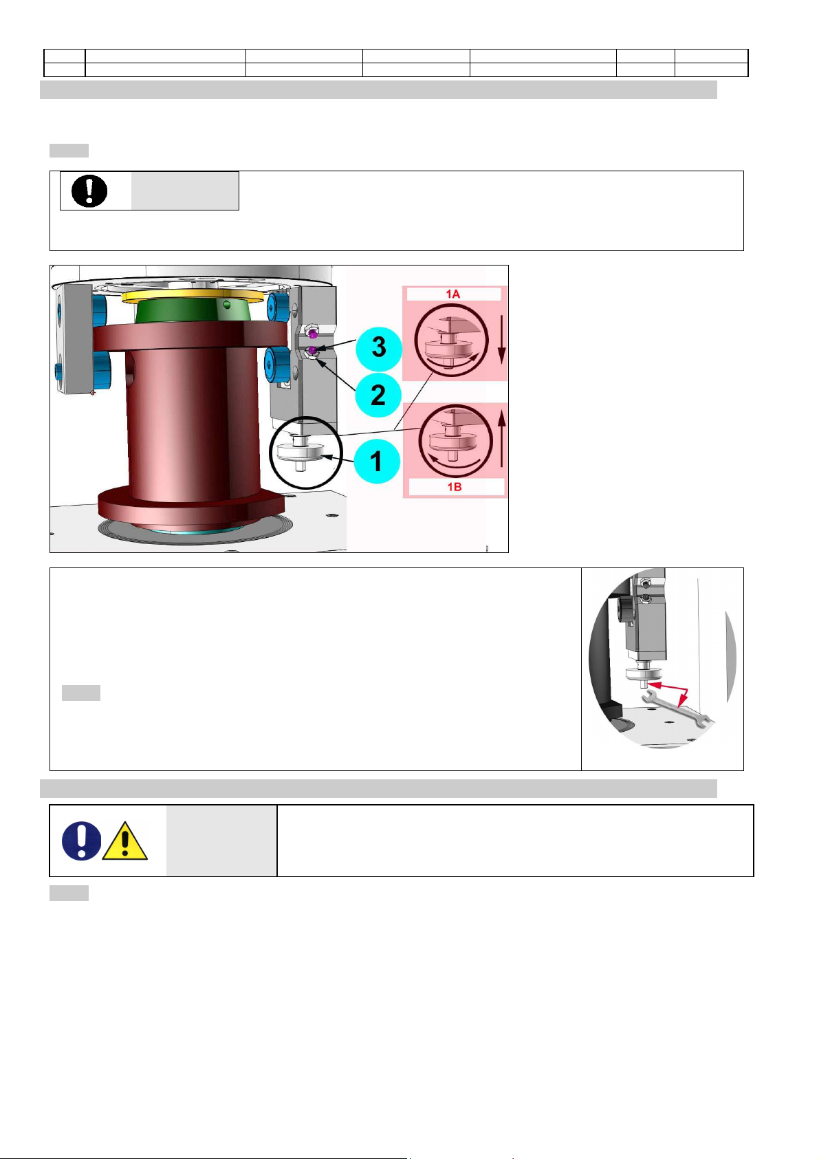
6.01
REGULATIONS
ATTENTION
The Matest Gyratory Compactor is calibrated at the factory to perform a set
gyration angle (lock position “1B”) and null angle (lock position “1A”). The
gyration angle can be changed within a working range acceptable for the
machine, adjusting the two dowels and nuts (“2” and “3”) placed on the selector. N.B.: THE MACHINE
CALIBRATION DECAYS IF THE FACTORY SETTINGS ARE CHANGED.
The gyration angle is set by the
hand grip selector that moves
vertically 2 of the 5 wheels
conceived to guide the mould.
The selector enables the operator to
set two working positions:
•the gyration angle
•the null angle
When the machine is off the
operator can set the gyration angle
by turning the hand grip “1” of the
selector clockwise up to the lock
position “B1” (the wheels moves
vertically upwards), or can set the
null angle at lock position “1A” by
turning the hand grip
counterclockwise (the wheels moves
vertically downwards).
Being the Gyratory Compactor calibrated at the factory, we recommend to set the
angle at lock position “1B” without introducing the mould into the machine. If this
condition is followed, the operators can insert the mould, perform the test and then
take out the mould from the machine without adjusting the selector.
If necessary, the operator can set the angle even after a pre-compaction of the
specimen using the null angle. In this case the rotation of the hand grip may be
difficult and a monkey wrench may be necessary to adjust the angle.
6.02
CHECKING THE SAFETY DEVICES WORK
Before proceeding to a regular and continuous use of the equipment, check the
emergency stop works correctly by: starting and stopping the machine through the
main switch, starting the machine and opening the doors, starting the machine and
pressing the emergency button.
C
hapter
7
IN FUNCTION
-
USE
DANGER
WARNING
Before setting the machine in motion it is essential that the Operator and
Safety Manager have read the Instructions Manual and understood all parts
of the machine and activities linked to it (Risks, Dangers, Functionality,
Operation, Protections, Commands, etc.)
7.01
MACHINE CALIBRATION
–
METERS
-
INDICATORS
The machine is checked in the factory, using sample equipment periodically checked by officially recognised
institutes. These checks cannot guarantee that the machine, meters and indicators will provide accurate values
and results conforming to the standards in force in the countries the machine has been installed and used in.
Normally such norms envisage calibration check after every movement. In order to obtain correct values and
results it is therefore VITAL that the operator, once the machine has been installed and set up and before official
tests, has an officially recognised body check the machine characteristics, its calibration and results/values
reliability. The manufacturer is exempt from all responsibility in the case of direct and indirect damage from use of
the machine without officially approval by the relevant bodies.

Rev. Descrizione Redatto/Gestito Approvato Cod.Ident. Pagine Data Em.
0.6 Manuale Istruzioni GN UTEC B041.M01.EN 17/47 07/2014
ATTENTION
It is
NECESSARY
to perform the following Calibration Checks, respecting the
provided deadlines, in order to comply with the instructions of the International
Standards in force related to the test (EN 12697-10, EN 12697-31 / ASTM D6925
/ AASHTO T312), and to control the possible settlements and run in wear conditions of the machine and its parts:
LILT TIME
→
MACHINE
INSTALLATIO
N
EVERY
MONTH
EVERY
THREE
MONTHS
Note
METERS ↓
ANGLE OF
ROTATION X X ** ** each 50 tests
until reaching
200 tests
APPLIED
LOAD X X
SPECIMEN
HEIGHT X X
ROTATION
SPEED X X
MOULD AND
PISTON See standards reference.
Follow the laws in force in the
country where the machine has
been installed for correct
calibration checks. Depending
on the instructions provided by
the law and by the Standard in
force, or depending on the main
goal of the tests, the operator
has to refer to an accredited
laboratory or to set up a
complete laboratory equipped
with appropriate equipment and
procedures.
7.02
SWITCHING ON THE MACHINE
Position the main switch on “I
7.03
EQUIPPING
–
SAMPLE POSITIONING
1.
RAM ASSEMBLING
1
TRANSDUCER
CHECKING DISC
2
PISTON
Assemble the transducer checking
disc and the piston on the terminal
part of the ram rod.
Lock the 3 dowels and make sure
that the piston is well-locked
without any clearance.
ATTENTION
During the
assembling
procedure it is very important the operator
handles carefully all the partsto avoid
damages (incisions or dents) that may
affect negatively the execution of the test.
Rev. Descrizione Redatto/Gestito Approvato Cod.Ident. Pagine Data Em.
0.6 Manuale Istruzioni GN UTEC B041.M01.EN 18/47 07/2014
Type 2
If your PISTON has 3 teeth
and 3 screws (see photo), fit
the piston with the rod, when
in lowered position. Then
enter the 3 teeth. Once lined,
insert the 3 screws and
tighten them with the Allen
wrench, making sure that the
piston is permanently
blocked.

Rev. Descrizione Redatto/Gestito Approvato Cod.Ident. Pagine Data Em.
0.6 Manuale Istruzioni GN UTEC B041.M01.EN 19/47 07/2014
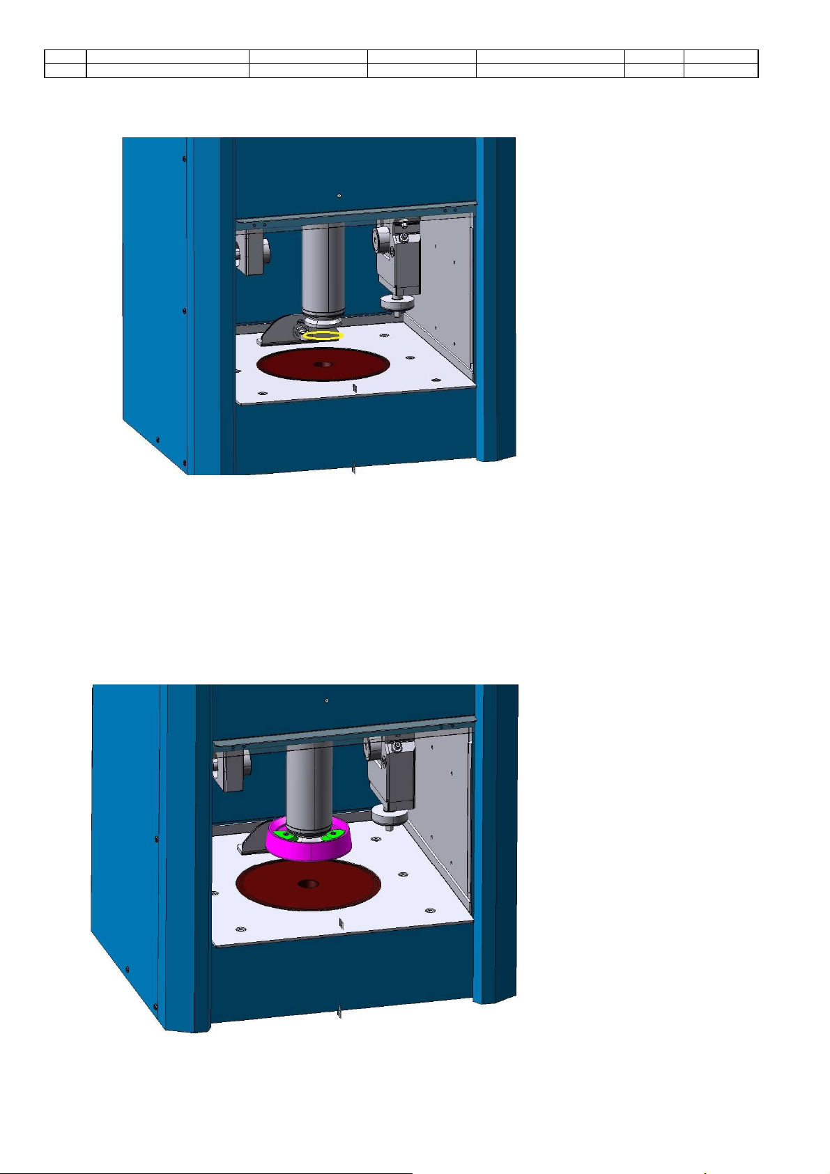
2.
CLEANING AND LUBRICATING
ATTENTION
An accurate cleaning of the
mould andall parts inside the
machine TEST CHAMBER is very
important for a good test
execution.
Failure to properly clean and
lubricate all the above mentioned
parts of the machine before each
use may result in compaction
errors, and premature equipment
wear.
After cleaning the machine, cover all
the parts with a thin layer of grease
or oil to protect them from rust.
1
WORKTOP A good cleaning condition must be maintained to avoid that impurities may be brought into
the test chamber when the operator drags the mould.
2
INTERNAL
PLATE
3
BASE DISC
The surface of the base disc is involved with the test execution and the mould bottom crawls
on with circular motion.
ATTENTION
For a correct test execution, it is very important that no
impurities are present between the bottom of the mould and
the surface of the base disc.
ATTENTION
It is of primary importance that a thin
layer of grease is laid on its surface to
avoid the seizing between the disc and
the bottom of the mould.
Use "Molykote ® Gn Plus" or
equivalent.
4
PISTON
It is very important that after each test the piston is cleaned properly to avoid incrustations.
5
TRANSDUCE
R CHECKING
DISC
The upper surface of the disc must be clean and without impurities as it works as checking
disc of the “T” sensor that reads the set angle.
6
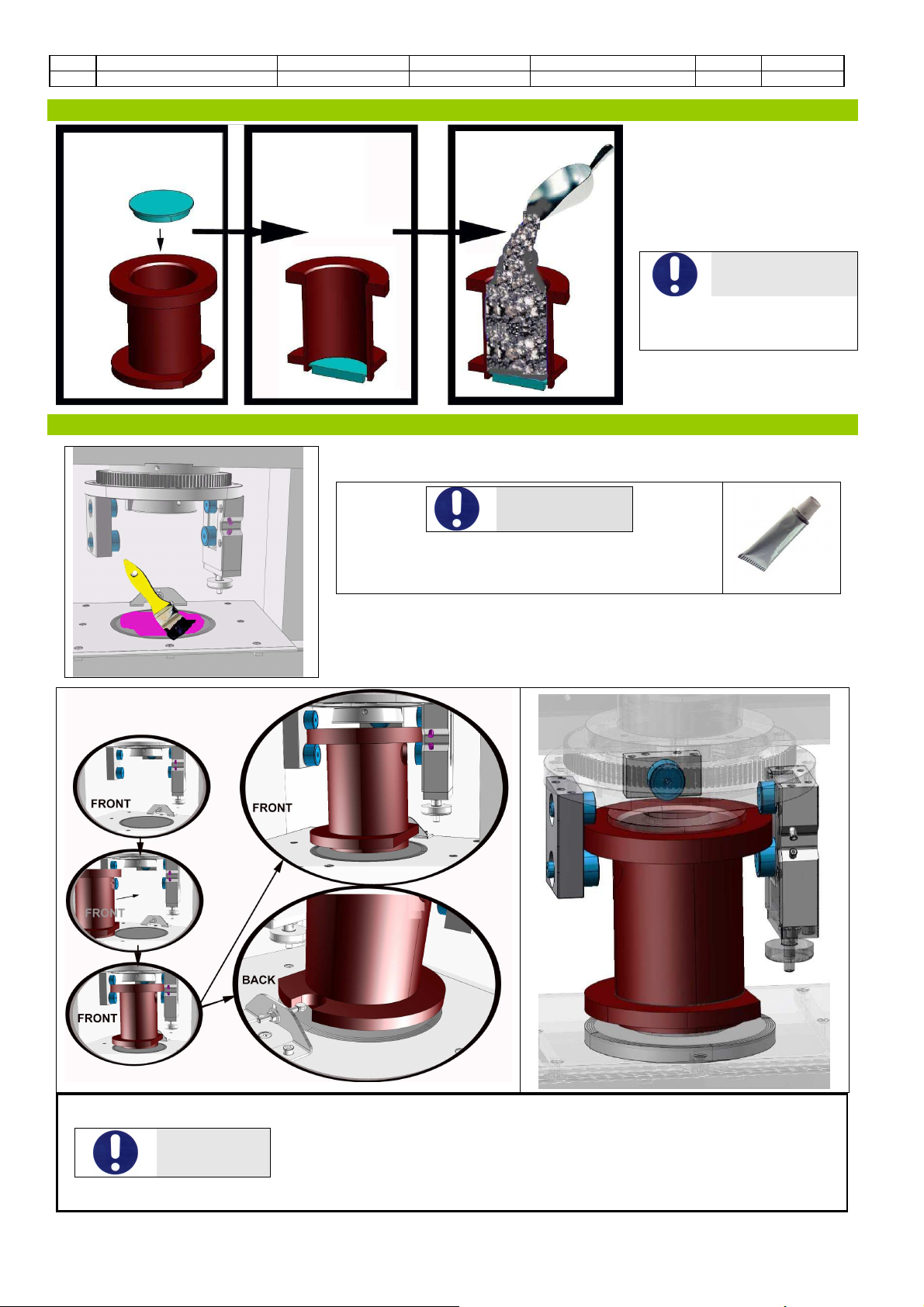
WHEELS Their position and the circular motion generate the movement of the mould.
Their surfaces get in contact directly with the lubricated upper and lower collars of the
mould. No impurities must be present between these surfaces.
1
MOULD UPPER COLLAR SURFACES
These surfaces are in contact with the
machine wheels.
It is very important to keep them clean and
slightly lubricated with generic gear oil.
2
ANTI-ROTATION SLOT
This surface may be subjected to frictions
caused by the anti-rotation pin of the
machine. It is very important to keep it
lubricated with a thin layer of grease to avoid
noise and wear process.
Rev. Descrizione Redatto/Gestito Approvato Cod.Ident. Pagine Data Em.
0.6 Manuale Istruzioni GN UTEC B041.M01.EN 20/47 07/2014
3.
SPECIMEN POSITIONING
•Insert the lower plate (puck)
into the mould (use the
extruder to make this operation
easier).
•Pour the asphalt mixture into
the mould.
ATTENTION
Make sure both sides of the
mould’s upper collar are
clean
4.
INTRODUCING THE MOULD INTO THE MACHINE
ATTENTION
Spread a thin layer of grease on the base disc as
specified in paragraph "3" of the section "Cleaning
and lubrication."
Drag and put the mould into the machine test chamber, paying attention
to let the slot at the bottom of the mould turned towards the back.
ATTENTION
Make sure the anti-rotation pin is aligned with the slot placed at the bottom of
the mould. Make sure that the upper collar of the mould has been inserted
correctly between the lateral wheels and under the rear wheel; the mould must
be at the center of the machine base plate. This operation is very easy as the
base plate of the machine and the lower plate/puck of the mould have the
same diameter.
Table of contents
Other Matest Industrial Equipment manuals

Popular Industrial Equipment manuals by other brands


TigerStop
TigerStop TigerFence user manual

WeighPack Systems
WeighPack Systems SPINDEXER 1800 Operator's manual

Powertrain
Powertrain WALTERSCHEID EK62/2S-L Repair instructions

Huvema
Huvema XOTR 60 S instruction manual

ubicquia
ubicquia ubigrid DTM+ installation manual

MachineryHouse
MachineryHouse SIEG SUPER X3 instruction manual


