WeighPack Systems SPINDEXER 1800 User manual

SPINDEXER 1800
OPERATOR’S MANUAL

2 December, 2017
PREFACE
Thank you for purchasing from WeighPack Systems Inc.
It is strongly recommended that this manual be read before use of the WeighPack machine.
This manual contains detailed descriptions of the structure, function, operation and maintenance of the
WeighPack machine. Please note that due to continuous improvements, the contents of this manual may
differ slightly from the machine received. In the event this document cannot provide the answers to
problems arising from machine operation or other circumstances, please contact the WeighPack service
department immediately.
CONTACT US
Head Office Phone Number
1-888-WEIGHPACK
Tech Support Email Address
TECHSUPPORT@WEIGHPACK.COM
WeighPack Website
WWW.WEIGHPACK.COM

3
December, 2017
TABLE OF CONTENTS
PREFACE ...................................................................................................................................... 2
CONTACT US ................................................................................................................................ 2
TABLE OF CONTENTS....................................................................................................................... 3
SAFETY ......................................................................................................................................... 4
INJURY PREVENTION ................................................................................................................... 4
FIRE PREVENTION........................................................................................................................ 4
ELECTRICAL PRECAUTIONS........................................................................................................... 4
WARNING LABELS .......................................................................................................................... 5
MACHINE SPECIFICATIONS .............................................................................................................. 6
MACHINE OVERVIEW...................................................................................................................... 7
SPINDEXER1800 SENSOR LOCATIONS ............................................................................................ 8
INSTALLATION OF ELECTRONICS ....................................................................................................... 9
INSTALLATION OF AIR SUPPLY ........................................................................................................... 9
MECHANICAL ASSEMBLIES............................................................................................................. 10
STAR WHEEL DISASSEMBLY.......................................................................................................... 10
CONTROLS.................................................................................................................................. 15
ALARMS.................................................................................................................................. 15
DOORS................................................................................................................................... 15
EMERGENCY STOP.................................................................................................................... 15
ELECTRICAL SCHEMATICS .............................................................................................................. 16
HUMAN-MACHINE INTERFACE (H.M.I.)............................................................................................ 17
MACHINE OPERATION .................................................................................................................. 32
MAINTENANCE ............................................................................................................................ 33
STORAGE ................................................................................................................................ 33
CLEANING .............................................................................................................................. 33
WEEKLY MAINTENANCE ............................................................................................................. 35
GENERAL MAINTENANCE........................................................................................................... 35
LIABILITY DISCLAIMER ................................................................................................................... 36

4 December, 2017
SAFETY
IMPORTANT SAFETY INFORMATION
READ ALL INSTRUCTIONS BEFORE OPERATING
Do not operate the machine when tired, ill, or under the influence of alcohol, drugs or medication.
The instructions and data in this manual are vital to the proper installation and operation of the machine.
In order to avoid accidents due to faulty installation or operation of the machine, please ensure that these
instructions are read by the individuals who will install, operate or maintain the machine. The instructions
issued in this manual are not meant to cover all possible conditions and situations that may occur.
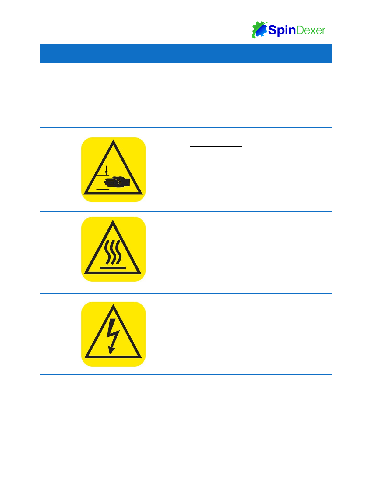
INJURY PREVENTION
1. Limbs, hair, loose clothing and accessories should remain clear of moving or heated parts of the
machine, as it may get caught and pull the operator into the machine.
2. Do not power on the machine if any of the machine’s components have been removed or modified.
3. Do not to leave any objects near any of the machine’s moving components, or on top of the machine.
4. Do not perform maintenance or cleaning on machinery while it is in operation or energized.
5. Always lock out / tag out the machine before performing any maintenance work.
FIRE PREVENTION
1. Keep a fire extinguisher near the machine.
2. All electrical components must be kept dry, clean and in good condition.
3. Lockout / Tagout the machine before maintenance.
Electrical fires can occur if any wires are scratched, corroded, color-faded, uninsulated, or
have damaged ends. Wires should be changed immediately if presenting any of the above
conditions. Any exposed electrical components should never come into contact with the
ground-connector or any other electrically conductive objects; such as tools.
ELECTRICAL PRECAUTIONS
1. Only trained professionals should install, examine and maintain the electronics of the machine.
2. Do not store liquids near the machine or near the machine’s electrical components. Exposing
electrical components to excess moisture or direct contact with liquids risks a short-circuit.
3. Should a liquid spill onto the machine, turn off the power immediately and once having cleaned the
liquid, test all the electrical components to ensure they are functioning properly.
4. To avoid short-circuiting, keep all wires and connections clean. Keep limbs, hand-held tools, and any
other electrically conductive objects away from exposed electrical components.
5. Ensure the electrical cabinet is always closed, unless needed for maintenance.
6. The machine must be grounded. Ensure that the ground wire is firmly connected with the ground
before starting the machine.
7. After installation check all electrical connections and test all electrical circuits before powering on.
Improper connection of the machine’s grounding conductor can result in a risk of electrical
shock. Check with a qualified electrician or serviceman if there is doubt as to whether or not
the machine’s outlets are properly grounded.

5
December, 2017
WARNING LABELS
Warning labels serve to advise the operator of potential danger. Warning labels should be kept clearly
visible at all times, and are not to be ignored or removed from the machine. Removal of warning labels
from the machine could result in an increase in machine related accidents. Should the machine require a
replacement label please contact the company immediately.
S y m b o l
D e s c r i p t i o n
PHYSICAL HARM
Take caution when in the presence of moving parts
as they may cut, crush, dismember or otherwise
injure body parts in close proximity.
Loose clothing or accessories around moving
components may get caught and pull the user into
the machine.
BURN HAZARD
Many surfaces of the machine will become
extremely hot during the course of its operation.
Please avoid contacting the indicated hot surfaces
to avoid burns.
Surfaces will remain hot for an extended period of
time after powering down the machine. Ensure the
machine is completely cool before contact.
HIGH VOLTAGE
While powered, the machine’s electrical systems
possess sufficient voltage to electrocute any who
misuse it.
Do not attempt to tamper with the electrical
systems of the machine. If damaged wiring or
damaged circuits are discovered, please power the
machine down and contact the company
immediately.

6 December, 2017
MACHINE SPECIFICATIONS
PARAMETER
SPINDEXER 1800
POWER SUPPLY
230V(AC)
60HZ
30AMPS
1PHASE
SPEED*
UP TO150CONTAINERS PER MINUTE
(WITH 16 POSITION STAR WHEEL)
UP TO80CONTAINERS PER MINUTE
(WITH 8POSITION STAR WHEEL)
CONTAINER DIAMETER
1.5IN (38MM )UP TO6.13IN (156MM )
CONTAINER HEIGHT
1.5IN (38MM )UP TO12IN (305MM )
AIR PRESSURE
80PSI (5.5BAR )
AIR CONSUMPTION
0.5CFM (0.014M3/MIN )
WEIGHT
954LBS (433KG )
DIMENSIONS
LENGTH: 125.4IN (318.4CM )
WIDTH: 36.9IN (93.7CM )
HEIGHT: 60.4IN (153.3CM )
*SPEED MAY VARY DEPENDING ON CONTAINER TYPE

7
December, 2017
MACHINE OVERVIEW

8 December, 2017
SPINDEXER1800 SENSOR LOCATIONS

9
December, 2017
INSTALLATION OF ELECTRONICS
Only a qualified electrician should make electrical connections to the facility’s electrical
circuit. It is important to check if the ground wire is firmly connected to ground and
whether its resistance meets the owner’s requirements.
1. Check the voltage and phase of the incoming line of the machine after supplying the power. Close
each line and press the Start button on the control panel to supply power to the interface and the
P.L.C. If there are abnormal noises, stop the machine and turn off the power.
2. Do not power the machine again before determining what is causing the noise and resolving the
problem.
3. Static electricity can cause problems with electrical equipment and with operation, ensure that the
equipment is properly grounded during installation.
4. Double ground the machine and test its ground resistance, if resistance is less than 5OHM then it is
acceptable. Any auxiliary equipment should be grounded as well.
5. If static is present in bags, the installation of static eliminator may be required. If this feature is
needed, please contact the company for additional information.
INSTALLATION OF AIR SUPPLY
The Filter Regulator is found behind the Control Box of the SPINDEXER 1800. The SPINDEXER 1800
operates at 80PSI (5.5BAR) and has an air consumption of 0.5CFM (0.014M3/MIN.) It is important to ensure
that the air supply of the owner’s facility can meet these specifications. Before connecting to an air supply
and pressurizing the machine, ensure the Lubricator is filled halfway with Pneumatic Food Grade Oil.
To Adjust Air Pressure
1. Pull the knob to release it and adjust
the pressure.
2. If the knob is rotated clockwise, the
inlet pressure will increase, if rotated
counter clockwise it will decrease.
3. Press down on the knob to lock it in
place again once the pressure changes
have been completed.
IMAGE FOR REPRESENTATION ONLY

10 December, 2017
MECHANICAL ASSEMBLIES
WE RECOMMEND THAT THE OPERATOR HAVE THE FOLLOWING TOOLS AVAILABLE WHEN MAKING ADJUSTMENTS OR
MAINTAINING THE MACHINE:METRIC ALLEN KEYS,METRIC SOCKET SET,METRIC WRENCHES,VOLT METER,SCREW DRIVERS,
TAPE MEASURE,RULER,CALIPER,ADJUSTABLE WRENCHES AND A GREASE GUN.
STAR WHEEL DISASSEMBLY
Each Star Wheel used on the Spindexer is designed for a specific container size. To run another
container size, the machine must be re-fitted with a new Star Wheel. The Spindexer’s Star Wheel has
been designed to be removed and changed quickly and easily without the use of tools.
The following section details the step by step removal of the various interior components of the Spindexer
1800. All components may be reinstalled in the reverse order in which they were removed.
Begin by opening the Lexan doors of the Spindexer 1800, on both sides of the
machine.

11
December, 2017
Use the Control Panel’s H.M.I. screen to navigate to the Auto Screen and use
the Funnel Adjust controls to raise the Slide Gate / Funnel Assembly until it
reaches its maximum extension, at which point it will stop. The lifting column
cannot be raised higher than the upper limit built into the controls, due to
mechanical restrictions.

12 December, 2017
After the Slide Gate / Funnel Assembly has been moved up and out of the way,
twist the funnel clockwise and pull the funnel off of the assembly.
Remove the funnel from the interior of the machine.

13
December, 2017
Turn the five knobs shown above in a counterclockwise motion and remove
them and the spacers (if present) on top of the Star Wheel. Please take care not
to lose these knobs.
Lift the Star Wheel up and clear of the locating pins securing the Star Wheel in
place.

14 December, 2017
Remove the Star Wheel from the interior of the machine as shown above.
Please note that the Star Wheel must be removed from the back of the
machine, as the Star Wheel cannot clear the lifting column of the Slide Gate /
Funnel Assembly.
All of the Spindexer 1800s components may be reinstalled in the reverse order
in which they were removed. A new Star Wheel may be installed on the
machine by following these steps in reverse.

15
December, 2017
CONTROLS
For details concerning the H.M.I. Software and Machine Operation, please see their respective sections.
ALARMS
In the event of a machine malfunction, such as a jam, an alarm warning will display on the H.M.I. Touch
Screen. After an alarm has been triggered, the machine should be inspected and the alarm must be
cleared on the H.M.I. Touch Screen before the machine can continue normal operations. Alarms cannot
be ignored, as they require the operator to manually clear them before the machine can run again.
DOORS
The machine will halt all functions when the safety doors open. The doors must be closed and the green
reset button must be pressed before the machine may resume normal operation.
EMERGENCY STOP
Pressing the E-stop will cause the machine’s systems will become completely unpowered save for the
H.M.I. Air will be cut off from any pneumatics and any servos will immediately stop.
In the event that the Emergency Stop button is used to halt the machine, it must be reset again before the
machine can be powered again. To reset the Emergency Stop Button, pull out the Emergency Stop
button until it returns to its original position and then press the green M.C.R. (Master Control Relay)
button. The Emergency Stop button is now ready to be used again.
The user may also need to halt the functions of any interfacing machinery feeding the machine in the
event of an emergency.

16 December, 2017
ELECTRICAL SCHEMATICS
For detailed Electrical Schematics, please see the documents enclosed in the Customer Care
Documentation package.

17
December, 2017
HUMAN-MACHINE INTERFACE (H.M.I.)
HOME SCREEN
When the machine is first powered on, the Home Screen will appear, displaying the P.L.C. and H.M.I.
versions installed, the Login and Logout buttons as well as the navigation bar at the bottom of the screen.
Pressing the Login button will bring up an input Screen where the operator can enter their password to
access locked Screens of the H.M.I. Pressing the Logout button will log the operator out.
NAVIGATION BAR
The bottom of the Screen displays the Navigation Bar: The Home, Automatic, Testing, Manual, Recipe
and System buttons that can be accessed at any time in any screen. These buttons will always be
displayed, unless entering a submenu.

18 December, 2017
LOGIN
The Home Screen contains the Login button. There are three levels of access allowed by the machine,
public, supervisor and technician. A public user does not need to login to use the machine normally.

19
December, 2017
AUTO SCREEN
This screen allows the machine’s operator to start and stop the automatic container filling process and
make changes to bag making settings.
ALARM: Found on the bottom of the screen, this buttons displays all active alarms.
MAIN BUTTON: The large blue button on the right hand side of the screen with the word “Init.” is the
main button for the Auto Screen. The button will change depending on the state of the machine:
INITIALIZE: If the machine has just been started and this screen is opened then this button will
be blue with the word “Init.” on it. Press this button to set the machine back to the home position
to prepare for automatic operation.
START: Press this button to begin filling containers automatically.
STARTING: Is displayed when the machine is in the process of beginning an automated filling
run, pressing it does nothing.
STOP: Press this button to end the machine’s automated run, there will be a delay as the
machine comes to a stop and any filling operations finish.
STOPPING: Is displayed when the machine is in the process of stopping, pressing it does
nothing.

20 December, 2017
MACHINE STATUS:
MACHINE STATE: Displays the state of the machine: Not Initialized, Initializing, Initialized, Ready,
Starting, Running, Stopping, Stopped or In alarm.
An alarm will display if there is a malfunction with the machine, such as a jam. When an alarm is
active the words “In alarm” will be displayed above the Recipe Number. The machine must be
inspected and the alarm reset before the operator can continue running the machine.
The alarm must be manually reset in the H.M.I, except when the E-Stop button is pressed. If the
E-Stop button is pressed it must be pulled out to cease the alarm.
SEQUENCE STATUS: Displays the status of the machine’s sequences: Infeed Accumulation Wait or
Outfeed Backup Wait.
INTERFACE STATUS: Displays the status of the machine’s interfaced equipment: Slide Gate Loaded,
Scale Not Ready, Dump Request Sent or Slide Gate Empty.
Table of contents
Other WeighPack Systems Industrial Equipment manuals
Popular Industrial Equipment manuals by other brands

Komet
Komet JEL JSF manual

NEXCOBOT
NEXCOBOT TP-100-2 user manual

Aventics
Aventics R412012728-BDL-001-AC operating instructions

National Flooring Equipment
National Flooring Equipment Trolley-10 OPERATING & SERVICE MANUAL

Clamper
Clamper Solar SB 1000 18kA 6E/2S installation guide

cytiva
cytiva ÄKTA go operating instructions