Matest C314 User manual

Rev. Descrizione Redatto/Gestito Approvato Cod.Ident. Pagine Data Em.
03 Manuale Istruzioni Ufficio Tecnico Resp.Tecnico C314.M01.EN.03 1/18 03/2009
1
INSTRUCTIONS MANUAL
CLIMATIC CHAMBER
MANUAL CODE: C314/315
DO NOT ATTEMPT TO OPERATE THIS EQUIPMENT BEFORE READING AND COMPREHENDING THE
MANUAL IN ALL ITS PARTS
USERS
•MACHINE MANUFACTURERS
•DRAUGHTSMEN
•OPERATORS
•MAINTENANCE WORKERS
•ANY OTHERS
MATEST S.r.l.
Via delle industrie 25
24048 Treviolo
(Bergamo) Italy
Tel +39 0352055011
Fax +39 0352055055
Internet : www.matest.com

Rev. Descrizione Redatto/Gestito Approvato Cod.Ident. Pagine Data Em.
03 Manuale Istruzioni Ufficio Tecnico Resp.Tecnico C314.M01.EN.03 2/18 03/2009
2
GENERAL INDEX
Chapter 1 GENERAL INFORMATION
1.1 GENERAL FEATURES
1.2 IDENTIFICATION
1.3 APPLICATIONS
1.4 STRUCTURE AND OPERATING OF THE MACHINE
Chapter 2 SAFETY INFORMATION
2.1 GENERAL SAFETY STANDARDS
2.2 DANGEROUS PARTS AND RESIDUAL RISKS
2.3 NOISE
Chapter 3 INSTALLATION
3.1 LIFTING
3.2 UNPACKING
3.3 POSITIONING
3.4 ELECTRIC CONNECTION
Chapter 4 MACHINE FEATURES
4.1 FEATURES OF THE APPLIANCE
4.2 CALIBRATION
Chapter 5 OPERATOR INTERFACE
5.1 CONTROLS AND MESSAGES
Chapter 6 USE
6.1 SWITCHING ON THE APPLIANCE
6.2 SETTING UP THE APPLIANCE
6.3 STANDARD STARTING
6.4 STANDARD STOP
6.5 EMERGENCY STOP
6.6 SWITCHING OFF
6.7 TRIAL STARTING
6.8 EXAMPLE OF OPERATING
Chapter 7 MAINTENANCE
7.1 ROUTINE MAINTENANCE
7.2 CALIBRATION
7.3 SPECIAL MAINTENANCE
Chapter 8 DIAGNOSIS
Chapter 9 SCRAPPING
9.1 SETTING ASIDE
9.2 SCRAPPING
Chapter 10 ENCLOSURES
A GENERAL VIEW OF THE CONTROL PANEL
B ELECTRICAL LAYOUTS
EEC CONFORMITY DECLARATION (ONLY FOR EEC COUNTRIES)
ATTENTION All indications given in this manual must be followed carefully. In case they are not the warranty
terms will not be considered valid anymore.

Rev. Descrizione Redatto/Gestito Approvato Cod.Ident. Pagine Data Em.
03 Manuale Istruzioni Ufficio Tecnico Resp.Tecnico C314.M01.EN.03 3/18 03/2009
3
Chapter 1 GENERAL INFORMATION
1.1 GENERAL FEATURES
•This manual id addressed to the carrier, the installer, the user, the maintenance operator, and the scrapping
operator.
•Please read it carefully because it informs you about the operating of the machine in safety conditions.
•This manual has to be considered a part of the product and concerns only the machine it is delivered with.
•Keep the manual in order during the whole life of the appliance to consult it for any needs.
•In case of sale, the manual and its enclosures should be given together with the machine.
•The manufacturer assumes no liability for any damages caused by a misuse of the machine.
•The manufacturer has the right to modify this technical literature as well as the machines this refers to without any
previous notice.
•Messages meaning:
ATTENTION It shows the procedures that can damage seriously the machine if they are not followed carefully
1.2 IDENTIFICATION
MANUFACTURER IDENTIFICATION: See the cover page
MACHINE IDENTIFICATION: See the plate on the machine
1.3 APPLICATION
The appliance described in this manual is made for the execution of ageing tests, accelerated maturation tests, freezing
and unfreezing tests on concrete specimens.
This appliance has to be used only for the aim it has been projected and manufactured for.
Any other use of the machine is not permitted.
ATTENTION The instructions given in this operating manual are only made for the right use of the appliance. To carry
out the test in the right way, the user must refer to the specific standards in force for the test itself.
1.4 STRUCTURE AND OPERATING OF THE MACHINE
This appliance is composed by an insulated chamber with front door for the introduction of the specimens into the inside
chamber. The chamber is equipped with mobile shelves where specimens can be positioned.
A group of heating elements allows the heating of the temperature.
A freezing system allows the cooling of the temperature.
A system producing water steam allows setting the humidity required.
Regulators that check and keep the temperature and the humidity inside the chamber check all these systems.
If further information is required, get in touch with the dealer or the manufacturer.
Chapter 2 SAFETY INFORMATION
2.1 GENERAL SAFETY STANDARDS
•The use, lifting, installation, maintenance and scrapping of the machine are allowed only to QUALIFIED
STAFF.
Qualified staffs is composed by people who are authorised by the safety responsible to do any activities due to their
experience and acknowledgement of the operating of the machine and of the standards, rules and actions.
The user must be carefully taught about the operating of the machine to avoid any misuse of it and about the safety
devices, which the machine could be eventually equipped with. The safety devices will have to be kept always
assembled and to be daily checked.
The manufacturers offer training and assume no liability for any damages due to a misuse of the machine by an
unskilled staff.
•The manufacturer recommends following carefully the instructions and procedures of the operating manual and the
safety standards concerning the safety devices and the general rules of the work environment.
•Verify the accordance of the machine to the standards in force in the State where the machine has to be installed.
•The operating manual must be carefully read by the safety responsible, by the operators and maintenance engineers.
It must always be kept near the machine in order to be able to read it any times it will be necessary.

Rev. Descrizione Redatto/Gestito Approvato Cod.Ident. Pagine Data Em.
03 Manuale Istruzioni Ufficio Tecnico Resp.Tecnico C314.M01.EN.03 4/18 03/2009
4
•Any tampering or modifications of the machine (electric, mechanical etc.) that are not allowed by a written agreement
of the manufacturer must be considered as not permitted and the manufacturer will not accept to be charged for any
damages.
•The removal or the tampering of the safety devices will be an infringement to the EEC Safety Standards. The
manufacturer assumes no liability for any damages.
•The machine has to be installed in places safe from fire and explosions.
•We do recommend using only original spare parts and accessories; on the contrary the manufacturer assumes no
liability.
•Be careful that any dangerous situations won't happen during the working; stop immediately the machine in the event
that it will not work properly and ask the manufacturer or the Authorised Service Staff of the dealer at once.
The manufacturer assumes no liability for any damages to people, things and animals caused by the non-compliance of
the instruction manual.
2.2 DANGEROUS PARTS AND RESIDUAL RISKS
The dangerous place is the space inside and around the machine where the operator could be wounded or damaged.
During some procedures the operator could face some risks of danger.
All these risks can be eliminated, if all procedures explained in the manual are followed and if individual safety devices
are properly used.
DANGER 120° C. hot steam can be expelled during the working of the appliance from the emergency water drain
pipe on the back lower part of the chamber.
Do not stay near to the drainpipe and ensure that the installation has been made following the
indications given in this manual in order to collect and expel the steam without any risk for people and
things around the appliance.
DANGER Do not introduce persons, animals or objects other than specimens to be used for the test inside the
chamber.
DANGER Do not wash the appliance with water sprays
The manufacturer assumes no liability for any damages to people and things due to a lack of observance of the
instructions and the use of adequate personal safety devices (Following the local laws against the accidents).
2.3 NOISE
The indicated levels of noise are not necessarily safety levels for the operator.
The exposure levels of the operator are obviously related to the emission levels of the appliance, but other factors
influence the exposure levels as the time of exposure, the environment, other appliances installed near to the appliance
etc.
The exposure levels permit to value the damages that could be caused by the noise
Acoustical pressure level equivalent Laeq at 1 m distance 56 dB(A)
Acoustical power emitted by the appliance LWA………….. 61 dB(A)
Standard above data are referred EN ISO 3746
DANGER The continuous use of the machine together with other noisy appliances could cause a high level of
exposure to the noise. If the daily exposure of the operator is equal or higher than 85 dB(A), Safety
Devices as headphone are suggested to be worn.
If the daily exposure is equal or higher than 90 dB(A), the use of the Safety Device is compulsory.
For further information consult the standards of the country where the machine has been installed.
Chapter 3 INSTALLATION
DANGER Consult 2.2 DANGEROUS PARTS AND RESIDUAL RISKS before proceeding
3.1 LIFTING
The operating instructions must be respected during:
•The lifting and the storing
•The first installation

Rev. Descrizione Redatto/Gestito Approvato Cod.Ident. Pagine Data Em.
03 Manuale Istruzioni Ufficio Tecnico Resp.Tecnico C314.M01.EN.03 5/18 03/2009
5
•The further installations
The machine is usually packed shipped in a wooden case that allows an easy moving and transport.
The case must be moved by means of a forklift with enough capacity to lift the weight given in this manual for the
appliance.
ATTENTION Pay attention to avoid impacts and turnovers
ATTENTION Protect the machine from the atmospheric agents. Water and humidity could oxidise it, damaging it
seriously.
3.2 UNPACKING
After removing the package, check that any parts of the machine are not damaged. In case of doubt, DO NOT USE THE
MACHINE and ask the manufacturer.
DANGER The materials used for the package (plastic, polystyrene, screws, nails, wood etc.) have to be kept far
from children. They must be thrown away in a proper collection centre.
ATTENTION Before throwing away the package, pay attention that any accessories, manuals, documents, spare
parts are not inside.
3.3 POSITIONING
•The appliance must be placed in a position and a site suitable for the use it has been conceived (use in a laboratory
safe from atmospheric agents); qualified staff must arrange the installation.
Admitted temperature: from 5° C. up to 40° C. (for a proper working of the climatic chamber we do
recommend placing it in a dusty free environment, properly aired and with a room
temperature between 14° C. and 26° C.)
Allowed humidity: from 30% to 95%
O.S.L max. height: 1000 meters.
The machine must be installed so that it is free from each side in order to be able to carry out easily the maintenance
operations (free space around the appliance: at least 50 cm. on each side).
•No authorised people and no dangerous objects must be near the machine.
•Check that the appliance is perfectly levelled in order to be able to close the door perfectly.
•The main working position for the operator is in front of the appliance.
No authorised people and no dangerous objects are allowed to stay in the area around the machine.
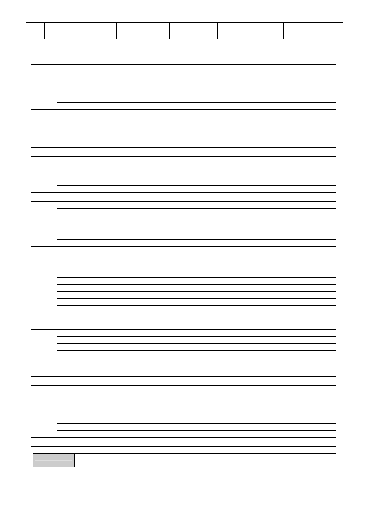
•Clean carefully inside the chamber using a cloth with some alcohol on it in order to clean out the protective oils, wash
with cold or tepid water and dry with care. (The manufacturer recommends not to use any detergent or chemical).
•Position the selves/trays on the relative supports (4 for each tray).
•Connect the Climatic Chamber to a water network in order to supply water sufficiently cold. If the water temperature is
not cold enough, a refrigerator is required.
The climatic chamber have to be connected to the water net by means of the relevant coupling device dia. 10 mm
placed on the left top of the climatic chamber back side.
•Connect the emergency drain (cupper pipe on lower back side on the right) to a water drain paying attention to use a
pipe as much as short and large as possible in order not to create any obstacle to the water flow.
DANGER Temperature of the water on the water drain can be 120º C.
3.4 ELECTRIC CONNECTIONS
DANGER Skilled operators must arrange the electric connections.
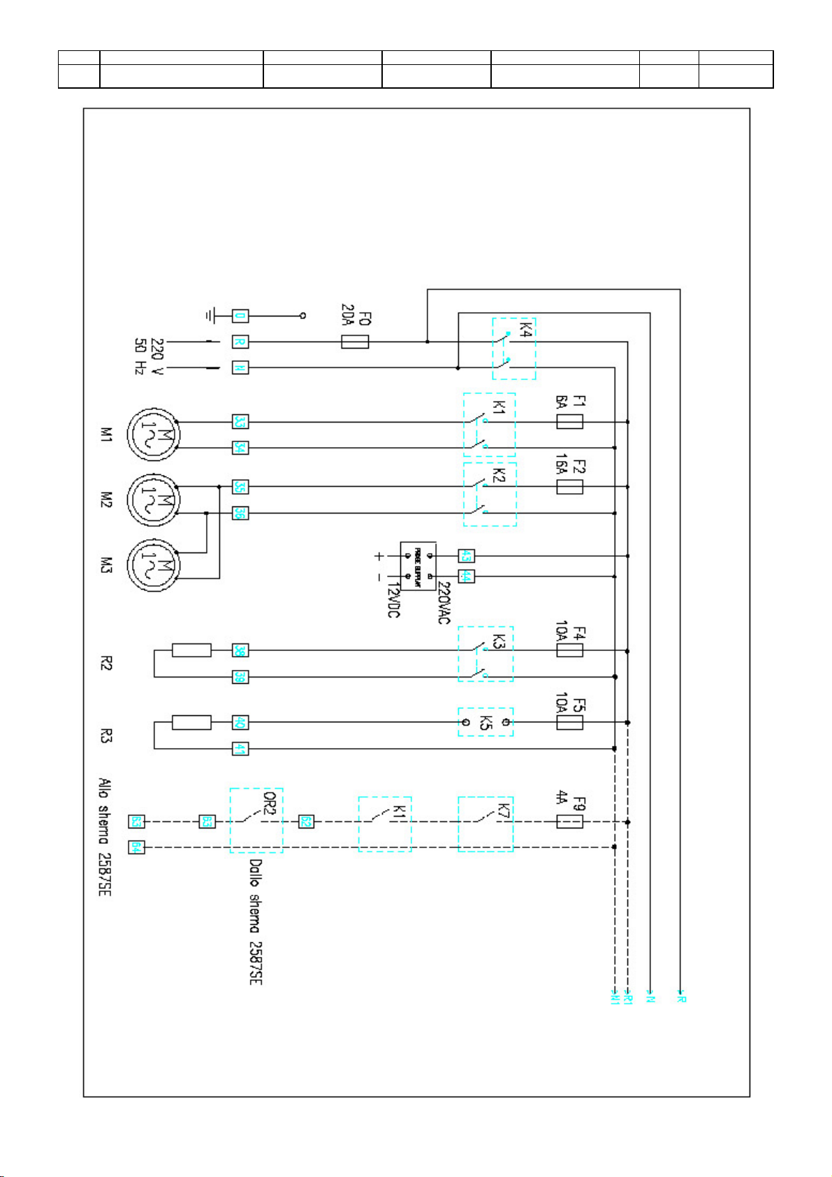
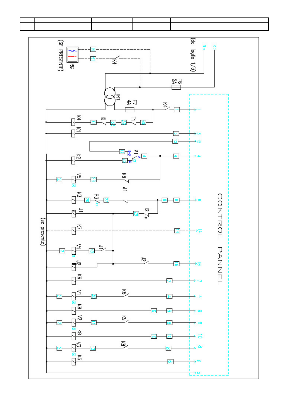
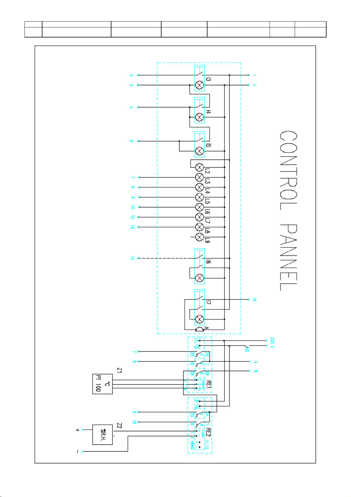
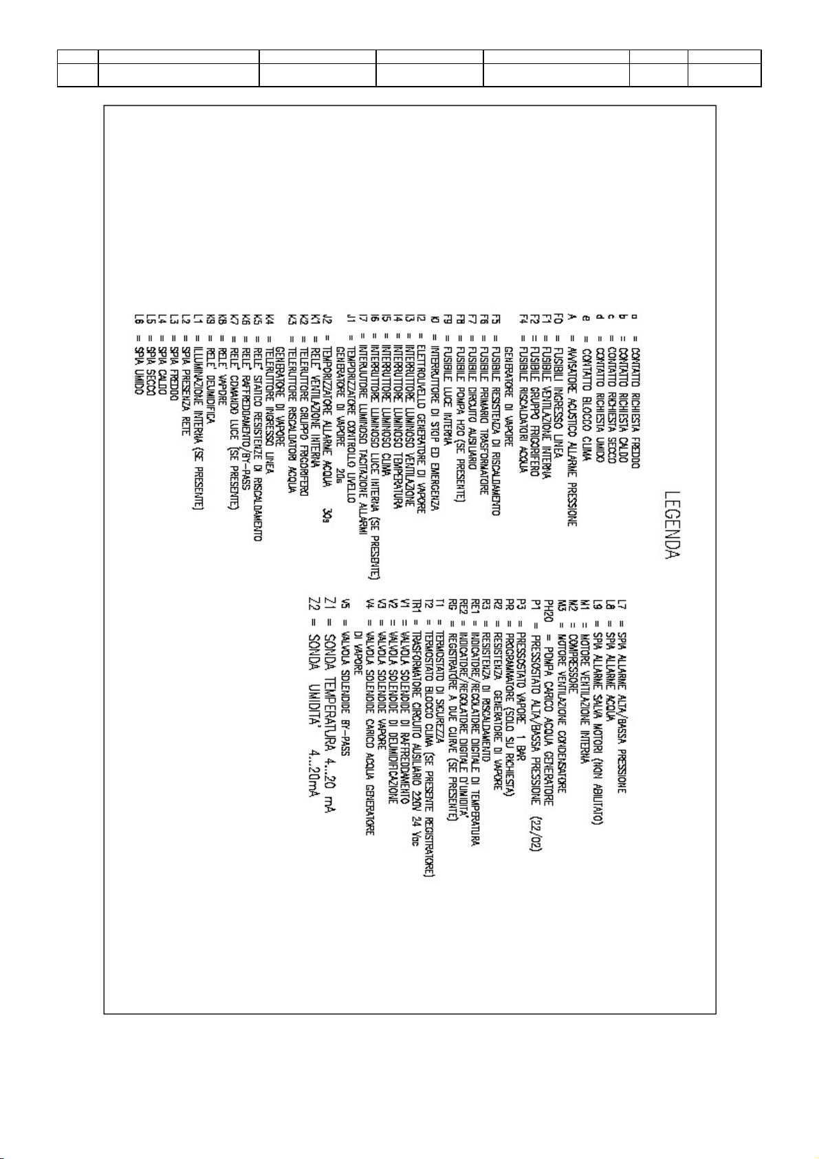
DANGER Before connecting, see the attached electric diagram and the plate on the machine for the information
about the voltage, the frequency, etc.
It is advisable to use demineralized water for a better functioning of the chamber and a better
maintenance of the moisturizing system.
It is advisable to use a decalcificator, model CULLIGAN Refill line soft 10 litres.
If the climatic chamber has been connected to the water network, check that the water hardness is not
higher than 12º f and not lower than 7ºf.
Check the pressure feed. If the pressure is higher than 3 bar, use a pressure reducer in order to keep it at 3bar.
It is also advisable to use a mechanical filter of 50 match.

Rev. Descrizione Redatto/Gestito Approvato Cod.Ident. Pagine Data Em.
03 Manuale Istruzioni Ufficio Tecnico Resp.Tecnico C314.M01.EN.03 6/18 03/2009
6
DANGER Connect the ground by the terminal PE (yellow-green) before making any other connections.
DANGER Apply a knife switch at the top of the connecting cable of the machine to the power system.
The knife switch must be combined with a safety device against the overload with a differential switch
(safety switch).
The technical features of the safety device must be in accordance with the standards in force in the
country where the machine has been installed.
ELECTRIC TOLERANCES:
•Real voltage ±10 % of the nominal one
•Frequency: ±1 % of the nominal one in a continuous way ±2 % of the nominal one for a short period
•The harmonic distortion of the sum from the second to the fifth harmonics not more than 10 % of the total voltage as a
real value between the conductors. A further distortion of 2% is accepted for the sum from the sixth to the thirtieth
harmonics of the real total value between the conductors.
•With reference to the tension unbalance of the three-phase voltage, the inverted sequence component and the zero
sequence component must not be more than 2% of the direct sequence component of the voltage
•The voltage pulses must not last more than 1,5 ms with an up/down time between 500 ms and 500 μs and a peak
value not higher than 200 % of the real value of the nominal tension.
•The electric feeding must not be interrupted or zeroed for more than 3 ms. Between two interruptions it must not take
more than 1 s.
•The interruptions must not overcome 20 % of the tension peak for more than one cycle. Between two interruptions it
must not take more than 1 s.
The manufacturer assumes no liability for any damages to people, things and animals caused by the non-compliance of
the above instructions.
Chapter 4 MACHINE FEATURES
4.1 FEATURES OF THE APPLIANCE
Model C314 C315
Capacity 520 1200
Temperature range -20 °C +60°C
Environment
temperature +10 °C - +60°C
Type of gas R 404 A
4.2 CALIBRATION
The machine is controlled and calibrated by the manufacturer, using sampling tools, which are periodically checked by
Official Institutions.
WARNING Laws now in force foresee the calibration checking after every machine lifting.
Once the machine is installed and ready to work, Official Institutions must check the calibration before
this can be used for official tests.
Chapter 5 OPERATOR INTERFACE
5.1 CONTROLS AND MESSAGES
A Main switch – Emergency push-button I Hot Signal lamp
B Ventilation push-button L Dry Signal lamp
C Temperature push-button M Moisture Signal lamp
D Climax push-button N Motor contactors Signal lamp
E Inside light push-button O Temperature alarm Signal lamp
F Push-button to turn off sound alarms P Water alarm Signal lamp
G Main supply Signal lamp Q Temperature regulator
H Cold Signal lamp R Humidity regulator
A Main switch – Emergency push-button

Rev. Descrizione Redatto/Gestito Approvato Cod.Ident. Pagine Data Em.
03 Manuale Istruzioni Ufficio Tecnico Resp.Tecnico C314.M01.EN.03 7/18 03/2009
7
It allows to turn on or to interrupt the working of the whole appliance.
B Ventilation push-button
It turns on the working of the temperature and humidity control systems and it turns on the inside ventilation.
C Temperature push-button
It activates the setting to keep the temperature set on the temperature regulator.
D Climax push-button
It activates the setting to keep the humidity set on the humidity regulator.
E Inside light push-button
It turns on the inside light (only if it is foreseen on the model of Appliance purchased)
F Push-button to turn off sound alarms
It turns on or turns off the sound signal (if foreseen: led on = sound signal on)
G Main supply Signal lamp
It states that the main is feeling the appliance.
H Cold Signal lamp
It states that the chamber is making the cooling cycle.
I Hot Signal lamp
It states that the chamber is making the heating cycle.
L Dry Signal lamp
It states that the room is making the dehumidifying cycle.
M Moisture Signal lamp.
It states that the room is making the humidifying cycle.
N Motor contactors Signal lamp
Not foreseen on this model of appliance.
O Temperature alarm Signal lamp
It states that the chamber has stopped because the highest temperature allowed has been passed.
This happens in case of damages to the inside instruments. Get in touch with the After Sales Service.
P Water alarm Signal lamp
It goes on when there is no more water feeling (from both the net or the tank).
Q Temperature regulator
It allows setting the wished temperature during the working of the appliance.
R Humidity regulator
It allows setting the wished humidity percentage during the working of the appliance.
Chapter 6 USE
DANGER Consult 2.2 DANGEROUS PARTS AND RESIDUAL RISKS before proceeding
6.1 SWITCHING ON THE APPLIANCE
To switch the appliance on act on the switch A(Main Switch – Emergency push-button) turning it on the side indicated
by the arrow.
6.2 SETTING UP THE APPLIANCE
The regulators allow to set the temperature and humidity values that have to be reached and kept inside the chamber
during the test.

Rev. Descrizione Redatto/Gestito Approvato Cod.Ident. Pagine Data Em.
03 Manuale Istruzioni Ufficio Tecnico Resp.Tecnico C314.M01.EN.03 8/18 03/2009
8
ATTENTION
The configuration of the programmed parameters is made in the factory using and introducing values
that allow obtaining a proper working of the system.
The manufacturer recommends entering the configuration menus of these parameters only after
having carefully studied and learned all the indications given in the enclosed instruction manual.
The manufacturer assumes no liability about the working of the appliance in case the original
configuration has been changed accidentally or by will.
Setting of the values To set the values proceed as follows:
•Turn on the appliance by the main switch “A”
•Act on UP or DOWN buttons to set the desired value (set-point) that will be shown on the lower display.
•Activate the “ SEL / ENT “ button to confirm.
•In these conditions the upper display gives the actual temperature (or the humidity) inside the chamber while the
lower display gives the programmed value.
6.3 STANDARD STARTING
Turn on the “Ventilation” push-button in order to turn on its signal lamp.
With this operation the working of the main control of the chamber is on.
Turn on the “Temperature” push-button in order to turn on its signal lamp.
With this operation the working of the temperature control of the chamber is on.
NOTE: The control will work only after the main control is on by the “Ventilation” push-button.
Turn on the “Climax” push-button in order to turn on its signal lamp.
With this operation the working of the humidity control of the chamber is on.
NOTE: The control will work only after the main control is on by the “Ventilation” push-button.
6.4 STANDARD STOP
To stop only the temperature control, act on the “Temperature” push-button (signal lamp will be off).
To stop only the humidity control act, on the “Climax” push-button (signal lamp will be off).
To stop the whole control of the working process, act on the “Ventilation” push-button (signal lamp will be off).
6.5 EMERGENCY STOP
Act on the device A(Main switch – Emergency push-button) pushing it
6.6 SWITCHING OFF
Act on the device A(Main switch – Emergency push-button) pushing it
6.7 TRIAL STARTING
Before starting the normal and usual utilisation of the appliance, check its right working, making at least one completely
empty cycle following the given procedures.
If problems occur during the use, check the Chapter “ DIAGNOSIS “.
If the instructions given in this manual do not give the solution to the problem occurred, get in touch with the nearest
Service Centre.
6.8 EXAMPLE OF OPERATING
RANGER The procedure described in this example must be carried out only after having carefully read and
perfectly understood all the indications contained in this manual.
The machine can be used in many different ways depending from the kind of test that has to be made.
We give here an "example procedure" which allows to an inexperienced operator to complete a whole test.
The experience in the time will allow optimising the use of the machine following one's own needs.
In the example below we suppose to set a climatic condition at 35° C with 50% humidity:
•Turn on the instrument acting on the switch A

Rev. Descrizione Redatto/Gestito Approvato Cod.Ident. Pagine Data Em.
03 Manuale Istruzioni Ufficio Tecnico Resp.Tecnico C314.M01.EN.03 9/18 03/2009
9
•Act on UP or DOWN buttons of the temperature controller in order to set the value of 35° C.
•Activate the “ SEL / ENT “ button to confirm the data.
In this condition the upper display gives the actual temperature(or humidity) inside the chamber while the lower
display gives the programmed value.
•Act on UP or DOWN buttons of the moisture controller to set the value of 50
•Activate the “ SEL / ENT “ button to confirm.
In this condition the upper display gives the actual temperature(or humidity) percentage inside the chamber
while the lower display gives the programmed percentage.
•Push the “Ventilation” button in order to turn on the signal lamp referring to it.
With this operation the working of the whole control of the chamber will be on.
•Push the “Temperature” button in order to turn on the signal lamp referring to it.
With this operation the working of the temperature control will be on.
•Push the “Climax” button in order to turn on the signal lamp referring to it.
With this operation the working of the humidity control will be on.
Starting form this very moment the control of the different processes starts and works in order to keep the temperature
and humidity values that have been set.
The reaching of the values that have been set can be checked by comparing the values given on the upper displays (real
value inside the chamber) and the lower displays (set value).
To stop the temperature control, push the “Temperature” button (the signal light will be off).
To stop the humidity control, push the “Climax” button (the signal lamp will be off).
To stop the whole control process, push on the “Ventilation” button (the signal lamp will be off).
Chapter 7 MAINTENANCE
DANGER All the maintenance operations must be carried out with the machine turned off and unplugged from the
knife switch.
DANGER Skilled operators instructed about the purposes the machine is made for must carry any kind of
maintenance operations concerning the components of the machine and of the electric components,
even those that may seem very simple.
7.1 ROUTINE MAINTENANCE
•Clean the condenser (positioned on the upper part of the chamber) at least once per month from dust and dirt using a
dry brush.
NB : A bad maintenance of the condenser will negatively affect the Climatic Chamber yield as well as its
good functioning and may also cause irreparable failures.i
•Clean the inner space once every six months at least, by following the below operating instructions:
- Switch the equipment off by means of the Amain switch
- Soup the inner spaces up and remove the possible impurities by means of a dry cloth.
•In order to maintain the efficiency of the machine, clean periodically all its parts. Avoid the use of solvents which
damage the painted parts as well as parts made by synthetic materials.
•Check periodically that the salt of the decalcificator – when assembled on the equipment – are in good conditions.
7.2 CALIBRATION
It is recommended to carry out a periodical calibration control, by official institutions in charge, according to
law now in force.
7.3 SPECIAL MAINTENANCE

Rev. Descrizione Redatto/Gestito Approvato Cod.Ident. Pagine Data Em.
03 Manuale Istruzioni Ufficio Tecnico Resp.Tecnico C314.M01.EN.03 10/18 03/2009
10
For any special maintenance operation (repairs, replacements or any other operation not described in this manual),
please ask the manufacturer
Chapter 8 DIAGNOSIS
Some easy to solve and simple problem, which can happen during the working of the appliance, are introduced in this
chapter.
ATTENTION All maintenance, checking, control and repairing operations of each part of the machine or of the electric
system, must be carried out by skilled operators instructed about the functions and working procedures
of the appliance.
FAILURE POSSIBLE CAUSE CURE
The machine doesn’t turn on No main supply Check the right switching on
Check that there is electricity on the
main board
Fuses have broken Replace the broken fuses with same
capacity ones
The safety stop has gone on because
of the high temperature Contact the After Sales Service
The set humidity is not reached No water supply Check the water feeding
Ventilation and Climax are not on Turn them on by the relative push-
buttons
Improper setting of the regulator Check the introduced value
The boiler is not heating Check the fuses
The steam solenoid is not working
properly Check the proper working of the
solenoid and check the fuse.
The inner temperature is too high The temperature Controller has not
been set correctly. Check the temperature Controller has
been set correctly.
The door is not perfectly close Check the door has been closed
The equipment is too noisy The equipment has not a correct
levelling. Check the equipment has been
levelled correctly in order to avoid
vibrations caused by a wrong
stabilization.
The door is not perfectly close Check the door has been closed
High level of condensation The environment moisture is too high
The door is not perfectly close Check the door has been closed
Chapter 9 SCRAPPING
9.1 SETTING ASIDE
In case of setting aside for a long time it is necessary to disconnect the electric feeding.
Execute all the maintenance operations.
Oil the parts that are not varnished and cover the machine against the dust.
9.2 SCRAPPING
When the machine is not used anymore, it is recommended:
•to disconnect the cable of the feeding
•Cover/destroy all the parts which may be dangerous as cutting, projecting or sharpened ones.
•Disassemble the machine and scrap it as per the actual laws.

Rev. Descrizione Redatto/Gestito Approvato Cod.Ident. Pagine Data Em.
03 Manuale Istruzioni Ufficio Tecnico Resp.Tecnico C314.M01.EN.03 11/18 03/2009
11
Chapter 10 ENCLOSURES
A GENERAL VIEW OF THE CONTROL PANEL

Rev. Descrizione Redatto/Gestito Approvato Cod.Ident. Pagine Data Em.
03 Manuale Istruzioni Ufficio Tecnico Resp.Tecnico C314.M01.EN.03 12/18 03/2009
12
B ELECTRICAL LAYOUTS

Rev. Descrizione Redatto/Gestito Approvato Cod.Ident. Pagine Data Em.
03 Manuale Istruzioni Ufficio Tecnico Resp.Tecnico C314.M01.EN.03 13/18 03/2009
13

Rev. Descrizione Redatto/Gestito Approvato Cod.Ident. Pagine Data Em.
03 Manuale Istruzioni Ufficio Tecnico Resp.Tecnico C314.M01.EN.03 14/18 03/2009
14

Rev. Descrizione Redatto/Gestito Approvato Cod.Ident. Pagine Data Em.
03 Manuale Istruzioni Ufficio Tecnico Resp.Tecnico C314.M01.EN.03 15/18 03/2009
15

Rev. Descrizione Redatto/Gestito Approvato Cod.Ident. Pagine Data Em.
03 Manuale Istruzioni Ufficio Tecnico Resp.Tecnico C314.M01.EN.03 16/18 03/2009
16

Rev. Descrizione Redatto/Gestito Approvato Cod.Ident. Pagine Data Em.
03 Manuale Istruzioni Ufficio Tecnico Resp.Tecnico C314.M01.EN.03 17/18 03/2009
17

Rev. Descrizione Redatto/Gestito Approvato Cod.Ident. Pagine Data Em.
03 Manuale Istruzioni Ufficio Tecnico Resp.Tecnico C314.M01.EN.03 18/18 03/2009
18
This manual suits for next models
1
Table of contents
Other Matest Industrial Equipment manuals