Aeroflex Weinschel 8310 Installation and operating instructions

-~
ARTISAN
®
~I
TECHNOLOGY
GROUP
Your definitive source
for
quality
pre-owned
equipment.
Artisan Technology
Group
Full-service,
independent
repair
center
with
experienced
engineers
and
technicians
on staff.
We
buy
your
excess,
underutilized,
and
idle
equipment
along
with
credit
for
buybacks
and
trade-ins
.
Custom
engineering
so
your
equipment
works
exactly as
you
specify.
•
Critical
and
expedited
services
•
Leasing
/
Rentals/
Demos
• In
stock/
Ready-to-ship
•
!TAR-certified
secure
asset
solutions
Expert
team
ITrust
guarantee
I
100%
satisfaction
All
tr
ademarks,
br
a
nd
names, a
nd
br
a
nd
s a
pp
earing here
in
are
th
e property of
th
e
ir
r
es
pecti
ve
ow
ner
s.
Find the Cobham / Aeroflex / Weinschel 8310-36-2-F at our website: Click HERE
Model 8310 IM-289A
Aeroflex / Weinschel 1
Manual Rev. 9-08
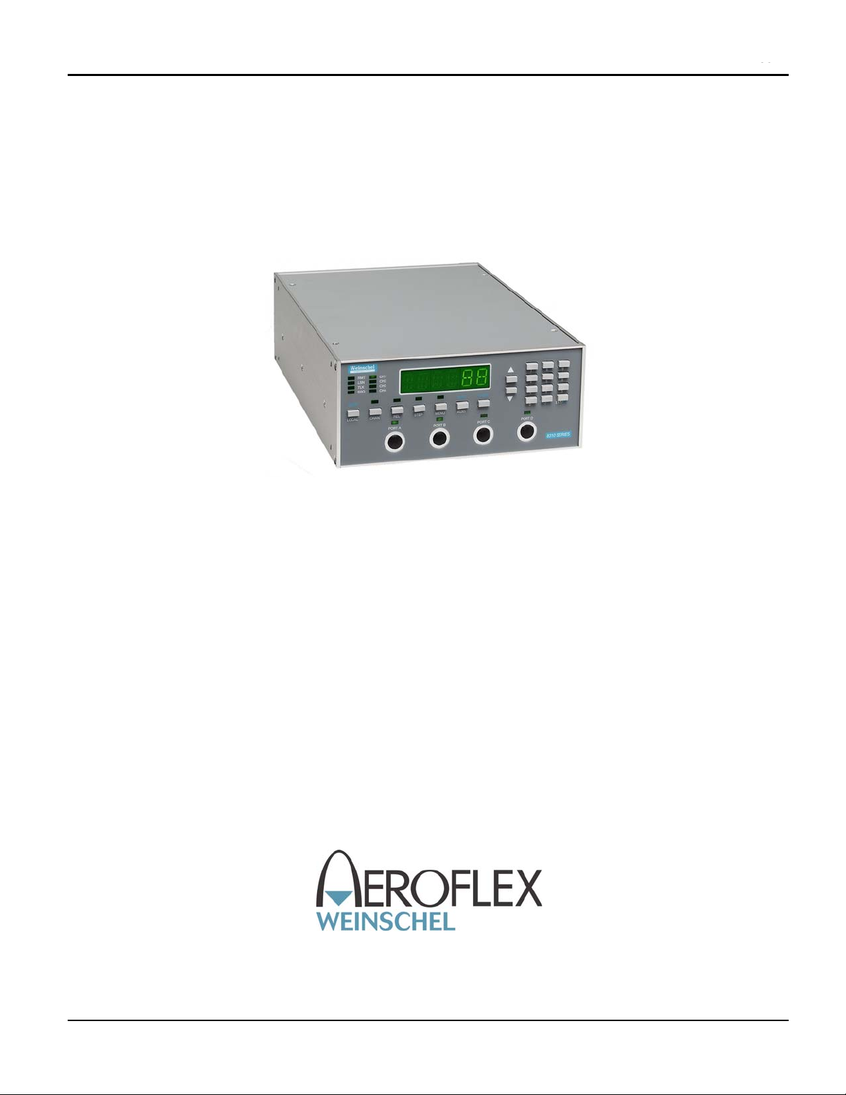
Operation & Service Manual
Model 8310
Programmable Attenuator Units
This documentation may not be reproduced in any form, for any
purpose unless authorized in writing by Aeroflex / Weinschel, Inc.
© Aeroflex / Weinschel, Inc.
Frederick, Maryland
1999-2006
IM-289A
TO A2-33AA36-533-1
Artisan Technology Group - Quality Instrumentation ... Guaranteed | (888) 88-SOURCE | www.artisantg.com
SAFETY SUMMARY
DEFINITIONS.
The following definitions apply to WARNINGS,
CAUTIONS, and NOTES found throughout this manual.
WARNING
An operating or maintenance procedure, practice,
statement, condition, etc., which, if not strictly
observed, could result in injury and/or death of
personnel. Do not proceed beyond a WARNING
symbol until all the indicated conditions have been
fully understood and/or met.
CAUTION
An operating or maintenance procedure, practice,
statement, condition, etc., which, if not strictly
observed, could result in damage or destruction of the
equipment or long-term health hazards to personnel.
Do not proceed beyond a CAUTION symbol until all
the indicated conditions have been fully understood
and/or met.
NOTE
An essential operating or maintenance procedure,
condition, or statement that must be highlighted.
GENERAL PRECAUTIONS.
The following are general precautions that are not related
to any specific procedure and, therefore, do not appear
elsewhere in this publication. These are precautions that
personnel must understand and apply during various phases of
instrument operation or service.
WARNING
•Potentially lethal voltages are present in this
instrument. Serious shock hazards from voltages
above 70 volts may exist in any connector,
chassis, or circuit board. Observe the following
precautions:
•To minimize shock hazard, the instrument chassis
must be connected to an electrical ground. Using
the supplied three-conductor power cable ensures
that the instrument can be firmly connected to the
ac power source and electrical ground at a
grounded power outlet. If using a 3-2 wire
adapter be sure to connect the ground lead to earth
ground.
•Use the buddy system any time work involving
active high voltage components is required. Turn
OFF the power before making/breaking any
electrical connection. Regard any exposed
connector, terminal board, or circuit board as a
possible shock hazard. DO NOT replace any
component or module with power applied.
•If test conditions to live equipment are required,
ground the test equipment before probing the
voltage or signal to be tested.
•Personnel working with or near high voltage
should be familiar with modern methods of
resuscitation.
•DO NOT wear jewelry (rings, bracelets, metal
watches, and/or neck chains) while working on
exposed equipment. Be very cautious about
using hand tools near exposed backplanes, bus
bars, and/or power supply terminals. Use
properly insulated tools. When making test
connections to the power supply terminals and
bus bars, use only insulated probe tips.
•Verify that the instrument is set to match the
available line voltage and the correct fuse is
installed.
•DO NOT install substitute parts or perform any
unauthorized modification to this instrument.
Contact Weinschel Corporation to acquire any
information on replacement parts or returning
the instrument for repair. Unauthorized
modification can cause injury to personnel and/or
destruction of the instrument.
•Operating personnel must not remove instrument
covers. Component replacement or adjustments
MUST BE performed by qualified service
personnel.
•DO NOT operate the instrument near or in the
presence of flammable gases or fumes.
DETAILED PRECAUTIONS.
The following WARNINGS, CAUTIONS and NOTES
appear throughout the text of this manual and are repeated here
for emphasis.
SAFETY SUMMARY
i
Artisan Technology Group - Quality Instrumentation ... Guaranteed | (888) 88-SOURCE | www.artisantg.com

CAUTION
•All procedures and/or steps identified as
must be followed exactly as written and
according to industry accepted ESDS device
handling procedures. Failure to comply WILL
RESULT in ESDS damage.
•DO NOT use a nylon bristle brush in the solvent
as the bristles may dissolve and cause damage to
the circuit card or component.
•DO NOT use ultrasonic cleaning on parts or
assemblies containing electrical or electronic
components.
•DO NOT bend pins of electrical connectors
when using fiber-bristle brush.
•Compressed air used for cleaning and/or drying
can create airborne particles that may enter the
eye. Goggles/faceshields should be worn. DO
NOT direct air stream towards self or other
personnel. Pressure should be restricted to a
maximum of 15 psi to avoid personal injury.
•Under no circumstances should a wire brush, steel
wool, or abrasive compound be used on any
surface. Using these items will cause extensive
damage to the instruments surface.
NOTE
DO NOT return any instrument or component to
Weinschel Corporation without receiving prior
factory authorization.
SAFETY SYMBOLS.
The following symbols are used to identify safety hazards
found throughout this publication and/or located on the
instrument.
WARNING
HIGH
VOLTAGE
CAUTION
HIGH VOLTAGE
SAFETY SUMMARY
ii Artisan Technology Group - Quality Instrumentation ... Guaranteed | (888) 88-SOURCE | www.artisantg.com

Model 8310 IM-289A
Aeroflex / Weinschel 2
TABLE OF CONTENTS
1. GENERAL INFORMATION....................................................................................................................................................5
1-1. PURPOSE ........................................................................................................................................................................................... 5
1-2. SCOPE ............................................................................................................................................................................................... 5
1-3. EQUIPMENT DESCRIPTION.......................................................................................................................................................... 5
1-4. USING THE 8310 (MODEL NUMBER INDEX) ............................................................................................................................. 5
1-5. UNPACKING AND INSPECTION................................................................................................................................................... 6
1-6. RESHIPMENT INSTRUCTIONS ..................................................................................................................................................... 6
1-7. STORAGE INSTRUCTIONS............................................................................................................................................................ 6
1-8. RELATED MANUALS..................................................................................................................................................................... 7
1-9. ELECTROSTATIC DISCHARGE SENSITIVE (ESD)..................................................................................................................... 7
1-10. ABBREVIATIONS & ACRONYMS .............................................................................................................................................. 7
1-11. SAFETY CONSIDERATIONS........................................................................................................................................................ 7
1-12. POWER REQUIREMENTS ............................................................................................................................................................ 7
1-13. ENVIRONMENTAL REQUIREMENTS........................................................................................................................................ 7
2. SPECIFICATIONS ................................................................................................................................................................................... 8
2-1. GENERAL SPECIFICATIONS......................................................................................................................................................... 8
2-2. PHYSICAL DIMENSIONS............................................................................................................................................................... 8
2-3. CONFIGURATIONS\RF SPECIFICATIONS..............................................................................................................................9-10
3. INSTALLATION....................................................................................................................................................................10
3-1. RACKMOUNTING......................................................................................................................................................................... 10
3-2. INTIAL SETUP ............................................................................................................................................................................... 10
3-3. INPUT/OUTPUT OPTIONS............................................................................................................................................................ 11
3-3.1. POWER ENTRY MODULE ASSEMBLY................................................................................................................................... 11
3-3.2. PORTS A-D CONNECTORS....................................................................................................................................................... 11
4. FRONT PANEL CONTROLS & INDICATORS..................................................................................................................12
5. REMOTE OPERATION........................................................................................................................................................13
5.1. IEEE-488 INTERFACE BUS CONNECTOR.................................................................................................................................. 13
5-2. GPIB ADDRESS/SERIAL COMMUNICATIONS SETTINGS..................................................................................................13-14
5-3. IEEE-488 (GPIB) BUS OPERATION ............................................................................................................................................. 15
5-4. SERIAL OPERATION .................................................................................................................................................................... 16
5-4.1. RS-232 OPERATION ................................................................................................................................................................... 17
5-4.2. RS-422/485 OPERATION ............................................................................................................................................................ 18
5-5. STATUS REPORTING...............................................................................................................................................................19-20
5-6. GENERAL SYNTAX STRUCTURE .............................................................................................................................................. 20
5-6.1. SYNTAX OF QUERIES............................................................................................................................................................... 20
5-6.2. SYNTAX OF COMMANDS ........................................................................................................................................................ 20
5-6.3. OUTPUT DATA FORMAT.......................................................................................................................................................... 21
5-6.4. NOTATIONAL CONVENTION.................................................................................................................................................. 21
5-7. 488.2 COMMON COMMANDS ................................................................................................................................................22-23
5-8. GENERAL COMMANDS..........................................................................................................................................................24-25
Artisan Technology Group - Quality Instrumentation ... Guaranteed | (888) 88-SOURCE | www.artisantg.com

Model 8310 IM-289A
Aeroflex / Weinschel 3
6. GENERAL CIRCUIT DESCRIPTION..................................................................................................................................26
6-1. POWER SUPPLY ASSEMBLY....................................................................................................................................................... 26
6-2. STATUS DISPLAYS AND SWITCH CONTROL ASSEMBLY.................................................................................................... 26
6-3. SMARTSTEP INTERFACE ASSEMBLY...................................................................................................................................... 26
6-4. RF SECTION................................................................................................................................................................................... 27
7. MAINTENCE.........................................................................................................................................................................28
7-1. INSPECTION................................................................................................................................................................................... 28
7.2. PREVENTIVE MAINTENANCE.................................................................................................................................................... 28
7.3. SPECIAL CLEANING INSTRUCTIONS ....................................................................................................................................... 28
7-3.1. MICROWAVE COAXIAL CABLE ASSEMBLIES ........................................................................................................ 28
7-3.2. CIRCUIT CARDS AND MODULES ............................................................................................................................... 28
7-3.3. MACHINED SURFACES AND HARDWARE ............................................................................................................... 29
7-3.4. CHASIS CLEANING........................................................................................................................................................ 29
7-3.5. CONNECTOR CLEANING.............................................................................................................................................. 29
7.4. LINE VOLTAGE FUSE REPLACEMENT..................................................................................................................................... 30
8. REPLACABLE PARTS LIST.................................................................................................................................................31
8-1. UNDERSTANDING REFERENCE DESIGNATORS.................................................................................................................... 31
8-2. ORDERING INFORMATION................................................................................................................................................. 32
8-3. DRAWING NUMBER............................................................................................................................................................. 31
8-4. REPLACABLE PARTS LIST.................................................................................................................................................. 31
8-4.1. REFERENCE DESIGNATOR.......................................................................................................................................... 31
8-4.2. DESCRIPTION................................................................................................................................................................. 31
8-4.3. PART NUMBER............................................................................................................................................................... 31
8-4.4. VENDOR PART NUMBER ............................................................................................................................................. 31
8-5.5. CAGE CODE .................................................................................................................................................................... 31
8-4.6. ASSEMBLY AND COMPONET LOCATION ................................................................................................................ 32
8310-1-F & -R, ATTENUATOR UNIT ASSEMBLY REPLACEABLE PARTS LIST (P/N 193-7001-1)..................... 32
8310-1-2-F & -R, ATTENUATOR UNIT ASSEMBLY REPLACEABLE PARTS LIST (P/N 193-7001-2).................. 32
8310-1-3-T, ATTENUATOR UNIT ASSEMBLY REPLACEABLE PARTS LIST (P/N 193-7001-3) .......................... 33
8310-2-F & -R, ATTENUATOR UNIT ASSEMBLY REPLACEABLE PARTS LIST (P/N 193-7002-1)..................... 34
8310-2-2-F & -R, ATTENUATOR UNIT ASSEMBLY REPLACEABLE PARTS LIST (P/N 193-7002-2).................. 34
8310-35-F & -R, ATTENUATOR UNIT ASSEMBLY REPLACEABLE PARTS LIST (P/N 193-7035-1)................... 35
8310-35-2-F & -R, ATTENUATOR UNIT ASSEMBLY REPLACEABLE PARTS LIST (P/N 193-7035-2)................ 35
8310-35-3-T, ATTENUATOR UNIT ASSEMBLY REPLACEABLE PARTS LIST (P/N 193-7035-3)......................... 36
8310-35-4-T, ATTENUATOR UNIT ASSEMBLY REPLACEABLE PARTS LIST (P/N 193-7035-4)......................... 36
8310-35-F-E & -R-E ATTENUATOR UNIT ASSEMBLY REPLACEABLE PARTS LIST (P/N 193-7035-5)............. 37
8310-35-4-T-E, ATTENUATOR UNIT ASSEMBLY REPLACEABLE PARTS LIST (P/N 193-7035-8)..................... 37
8310-36-F & -R, ATTENUATOR UNIT ASSEMBLY REPLACEABLE PARTS LIST (P/N 193-7036-1)................... 38
8310-36-2-F & -R, ATTENUATOR UNIT ASSEMBLY REPLACEABLE PARTS LIST (P/N 193-7036-2)................ 38
8310-36-3-T, ATTENUATOR UNIT ASSEMBLY REPLACEABLE PARTS LIST (P/N 193-7035-3)......................... 39
8310-37-F & -R, ATTENUATOR UNIT ASSEMBLY REPLACEABLE PARTS LIST (P/N 193-7037-1)................... 40
8310-37-2-F & -R, ATTENUATOR UNIT ASSEMBLY REPLACEABLE PARTS LIST (P/N 193-7037-2)................ 40
8310-37-3-T, ATTENUATOR UNIT ASSEMBLY REPLACEABLE PARTS LIST (P/N 193-7037-3)......................... 41
8310-37-4-T, ATTENUATOR UNIT ASSEMBLY REPLACEABLE PARTS LIST (P/N 193-7037-4)......................... 41
8310-38-F & -R, ATTENUATOR UNIT ASSEMBLY REPLACEABLE PARTS LIST (P/N 193-7038-1)................... 42
8310-38-2-F & -R, ATTENUATOR UNIT ASSEMBLY REPLACEABLE PARTS LIST (P/N 193-7038-2)................ 42
Artisan Technology Group - Quality Instrumentation ... Guaranteed | (888) 88-SOURCE | www.artisantg.com

Model 8310 IM-289A
Aeroflex / Weinschel 4
8310-38-3-T, ATTENUATOR UNIT ASSEMBLY REPLACEABLE PARTS LIST (P/N 193-7038-3)......................... 43
8310-38-4-T, ATTENUATOR UNIT ASSEMBLY REPLACEABLE PARTS LIST (P/N 193-7038-4)......................... 43
8310-38-F-E, ATTENUATOR UNIT ASSEMBLY REPLACEABLE PARTS LIST (P/N 193-7038-5) ........................ 44
8310-136-F & -R, ATTENUATOR UNIT ASSEMBLY REPLACEABLE PARTS LIST (P/N 193-7136-1)................. 45
8310-136-2-F & -R, ATTENUATOR UNIT ASSEMBLY REPLACEABLE PARTS LIST (P/N 193-7136-2).............. 45
8310-137-F & -R, ATTENUATOR UNIT ASSEMBLY REPLACEABLE PARTS LIST (P/N 193-7137-1)................. 46
8310-137-2-F & -R, ATTENUATOR UNIT ASSEMBLY REPLACEABLE PARTS LIST (P/N 193-7137-2).............. 46
8310-138-F & -R, ATTENUATOR UNIT ASSEMBLY REPLACEABLE PARTS LIST (P/N 193-7138-1)................. 47
8310-138-2-F & -R, ATTENUATOR UNIT ASSEMBLY REPLACEABLE PARTS LIST (P/N 193-7138-2).............. 47
8310-138-3-T, ATTENUATOR UNIT ASSEMBLY REPLACEABLE PARTS LIST (P/N 193-7138-3)....................... 48
8310-138-4-T, ATTENUATOR UNIT ASSEMBLY REPLACEABLE PARTS LIST (P/N 193-7138-4)....................... 48
8310-201-F & -R, ATTENUATOR UNIT ASSEMBLY REPLACEABLE PARTS LIST (P/N 193-7201-1)................. 49
8310-201-2-F & -R, ATTENUATOR UNIT ASSEMBLY REPLACEABLE PARTS LIST (P/N 193-7201-2).............. 49
8310-202-F & -R, ATTENUATOR UNIT ASSEMBLY REPLACEABLE PARTS LIST (P/N 193-7202-1)................. 50
8310-204-F & -R, ATTENUATOR UNIT ASSEMBLY REPLACEABLE PARTS LIST (P/N 193-7204-1)................. 50
8310-204-2-F & -R, ATTENUATOR UNIT ASSEMBLY REPLACEABLE PARTS LIST (P/N 193-7204-2).............. 51
8310-352-1-F & R ATTENUATOR UNIT ASSEMBLY REPLACEABLE PARTS LIST (P/N 193-7403-1)............... 52
8310-352-2-F & R ATTENUATOR UNIT ASSEMBLY REPLACEABLE PARTS LIST (P/N 193-7403-2)............... 52
8310-352-3-T ATTENUATOR UNIT ASSEMBLY REPLACEABLE PARTS LIST (P/N 193-7403-3)....................... 53
8310-352-4-T ATTENUATOR UNIT ASSEMBLY REPLACEABLE PARTS LIST (P/N 193-7403-4)....................... 53
8310 BASE ATTENUATOR UNIT ASSEMBLY REPLACEABLE PARTS LIST (P/N 193-8034).............................. 54
8310 BASE (+5V) ATTENUATOR UNIT ASSEMBLY REPLACEABLE PARTS LIST (P/N 193-8034-1)................ 55
9. APPLICATIONS....................................................................................................................................................................56
10. ACCESSORIES ....................................................................................................................................................................56
11. CONTACTING AEROFLEX / WEINSCHEL. ...................................................................................................................56
12. AEROFLEX / WEINSCHEL WARRANTY ......................................................................................................................57
13. ASSEMBLY/WIRING DIAGRAMS
MODEL 8310-1-X ASSEMBLY DRAWING ..............................................................................................................................193-7001
MODEL 8310-2-X ASSEMBLY DRAWING .............................................................................................................................193-7002
MODEL 8310-35-X ASSEMBLY DRAWING ............................................................................................................................193-7035
MODEL 8310-36-X ASSEMBLY DRAWING ............................................................................................................................193-7036
MODEL 8310-37-X ASSEMBLY DRAWING ............................................................................................................................193-7037
MODEL 8310-38-X ASSEMBLY DRAWING ............................................................................................................................193-7038
MODEL 8310-136-X ASSEMBLY DRAWING ..........................................................................................................................193-7136
MODEL 8310-137-X ASSEMBLY DRAWING ..........................................................................................................................193-7137
MODEL 8310-138-X ASSEMBLY DRAWING ..........................................................................................................................193-7138
MODEL 8310-202-X ASSEMBLY DRAWING ..........................................................................................................................193-7202
MODEL 8310-204-X ASSEMBLY DRAWING ..........................................................................................................................193-7204
MODEL 8310-352-X-X ASSEMBLY DRAWING ......................................................................................................................193-7403
MODEL 8310 BASE MODEL ASSEMBLY DRAWING...........................................................................................................193-8034
MODEL 8310 WIRING DIAGRAM ............................................................................................................................................193-8040
MODEL 8310 (+5V) BASE MODEL ASSEMBLY DRAWING............................................................................................193-8034-1
MODEL 8310 (+5V) WIRING DIAGRAM..................................................................................................................................193-8087
MODEL 8310-352-X-X WIRING DIAGRAM.............................................................................................................................193-8123
Artisan Technology Group - Quality Instrumentation ... Guaranteed | (888) 88-SOURCE | www.artisantg.com
Model 8310 IM-289A
Aeroflex / Weinschel 5
1. GENERAL INFORMATION:
1-1 PURPOSE: This manual contains setup and operation information for the Aeroflex / Weinschel’s 8310 Series of
Programmable Attenuator Units. The manual also provides component location, reference designators, part numbers,
and nomenclature to identify all the assemblies and sub-assemblies of the Attenuator Unit.
1-2 SCOPE: This manual is to be used in conjunction with the operation and maintenance of a 8310 Series
Programmable Attenuator Unit. The manual also provides a description of each assembly; assembly parts list; block
diagrams: and general maintenance procedures to maintain the instrument.
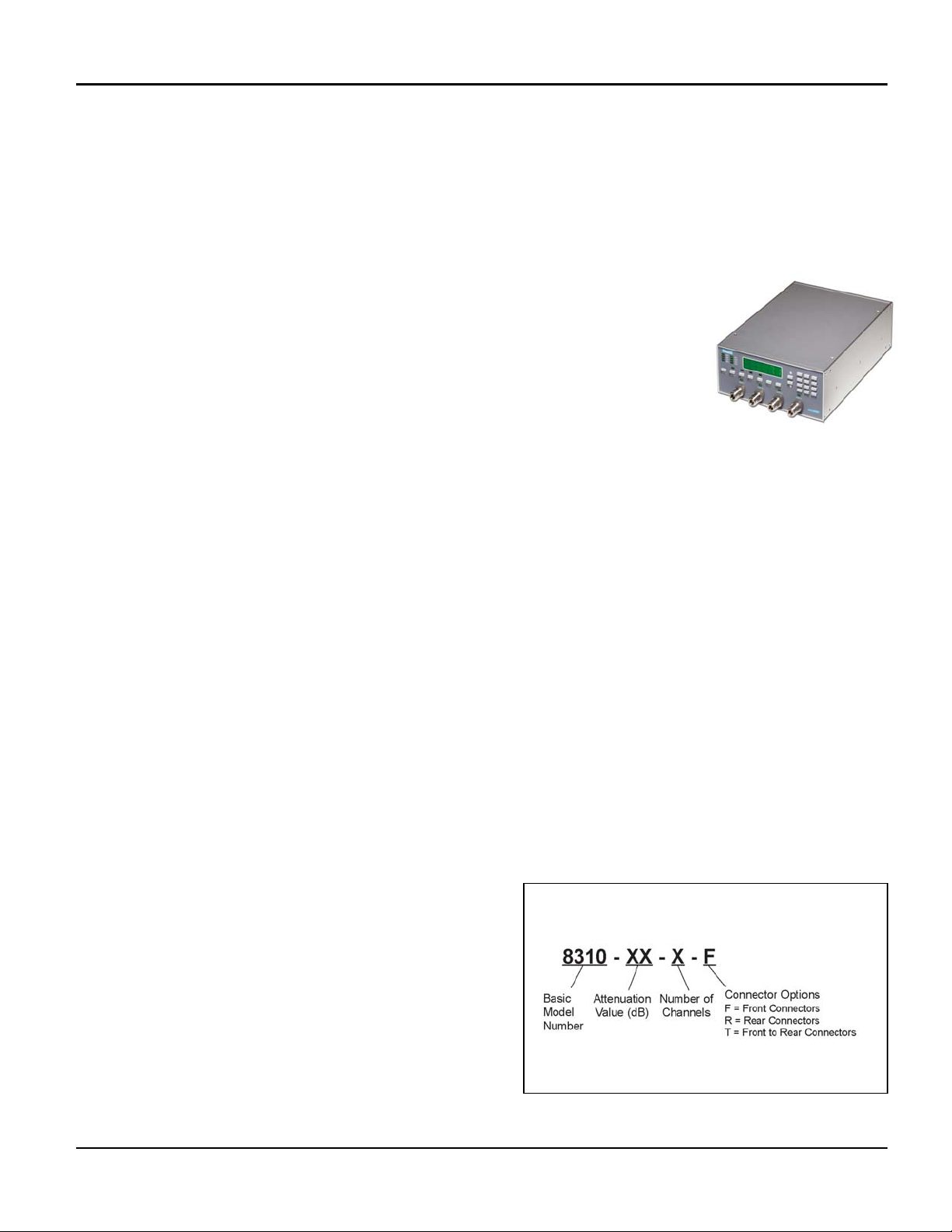
1-3 EQUIPMENT DESCRIPTION: Aeroflex / Weinschel’s 8310 Series Programmable
Attenuator Units represents a new concept in programmable attenuation for bench test
and subsystem applications. Standard Model 8310 designs house and control various
Aeroflex / Weinschel Programmable Attenuator Models (3200T, 150T, and 4200 Series)
via front panel controls or standard communications interfaces including GPIB (IEEE-
488) and RS-232/RS-422/RS485. Special configurations also exist where the RF section
is designed to specific customer requirements which can contain to multiple
programmable attenuations used in-conjunction with other coaxial devices such as
switches, power combiners, directional couplers, and filters creating single or multi-
channel subsystems.
1-4 USING THE 8310: The 8310 Series provides front-panel and computer control for up to four channels of
attenuation, RF switching, or other functions. The 8310 combines the features of the Aeroflex / Weinschel 8210A
Device Controller with a front panel user interface to form a flexible, easy to use solution. Most 8310 Series are single
channel configurations where RF signal is routed through either the front or rear mounted Ports A & B connector
(Ports A-A if the RF is routed front to rear) to a single or multiple Aeroflex / Weinschel programmable attenuators thus
creating CH1 (Channel 1). Note that when a Port is in use the Port indicator will be illuminated. Dual channel units
typically use Ports A and B for CH1 and Ports C and D for CH2 (Ports A-A if the RF is routed front to rear for CH1 and
Ports B-B for CH2). Multi-channel (3-4) units are generally routed front to rear and configured as follows:
CH1 Port A (Front) to Port A (Rear)
CH2 Port B (Front) to Port B (Rear)
CH3 Port C (Front) to Port C (Rear)
CH4 Port D (Front) to Port D (Rear)
For specialized configurations refer to supplemental
information in the front of this manual for details.
Typically Aeroflex / Weinschel digital attenuators are bi-directional and the RF signal can be applied to either Port
connector. Channels can be selected by toggling the front panel CHAN button until the desired CH1-CH4 indicator is
illuminated. Repeated depressions of the CHAN key will select the next available channel. The main display will show
the current attenuation setting of the channel. A new attenuation setting in dB may be entered using the INCR/DECR
or ENTRY keys. The front panel STEP key allows the user to define the attenuation step size used by the INCR and
DECR keys. Remember that the attenuation step size (resolution) is limited to the physical size of the internal
attenuator cells. For example a 0-70 unit with 10 dB steps can only be adjusted in 10 dB increments but larger
increments such as 20, 30, 40 dB can be set using this key.
The REL key allows the user to set relative mode for
attenuators. When turned on, the currently displayed
attenuation value is used as a reference value from which the
attenuation may be set. In this mode, attenuation values may
be positive or negative from the reference setting. When REL
is turned off, the display returns to the actual attenuation
setting for the channel. Refer to Section 5 for more detailed
information about the front panel keys and indicators. All 8310
Series functions can also be controlled via standard
communications interfaces including GPIB (IEEE-488)
and RS-232/RS-422 /RS485. Refer to Section 6 for bus setup
and operating instructions when using the 8310 Series in the
remote mode.
Model Number Index:
Artisan Technology Group - Quality Instrumentation ... Guaranteed | (888) 88-SOURCE | www.artisantg.com

Model 8310 IM-289A
Aeroflex / Weinschel 6
1-5. UNPACKING AND INSPECTION: Upon unpacking the equipment, retain the shipping container and packing
material for future shipment for recalibration. Perform the following initial inspection:
a. Carefully look at the outside of the shipping container for discoloration, stains, charring, or other signs of
exposure to excessive heat, moisture, or liquid chemicals. Check for any physical damage to the shipping
container such as dents, snags, rips, crushed sections or areas, or similar signs of excessive shock or
careless handling.
b. With the equipment and any accessory package removed from the shipping container, check each item
against the packing list or Items Supplied List. If any items are missing, contact the Weinschel Corporation
Customer Service Department.
c. Carefully inspect the equipment looking for dents, deep scratches, damaged or loose connector, or any other
d. signs of physical abuse or careless handling. If damage is found, forward an immediate request to the
delivering carrier to perform an inspection and prepare a concealed-damage report. DO NOT destroy any
packing material until it has been examined by an agent of the carrier. Concurrently, report the nature and
extent of damage to Weinschel Corporation, giving equipment model and serial numbers, so that necessary
action can be taken. Under U.S. shipping regulations, damage claims must be collected by the consignee;
DO NOT return the equipment to Aeroflex / Weinschel Corporation until a claim for damages has been
established.
1-6. RESHIPMENT: Use the best packaging materials available to protect the unit during storage or reshipment.
When possible, use the original packing container and cushioning material. If the original packing materials are not
available, use the following procedure:
a. Wrap the storage cases in sturdy paper or plastic;
b. Place the wrapped storage cases in a strong shipping container and place a layer of shock-absorbing material
(3/4 inch minimum thickness) around all sides of the unit to provide a firm cushion and to prevent movement
inside the container.
c. If shipping the unit for service, attach a tag to indicate:
1. model and serial numbers
2. service required
3. description of malfunction
4. return address
5. authorization to conduct repairs
6. return authorization number
d. Thoroughly seal the shipping container and mark it FRAGILE. Ship to:
Aeroflex / Weinschel, Inc .
Attn: Customer Service Department
5305 Spectrum Drive
Frederick, MD 21703-7362
or to an authorized sales representative.
1-7. STORAGE: Storage of the Model 8310 Series Programmable Attenuator Unit is possible for extended periods
without incurring damage to internal circuitry if the 8310 Series is packaged according to the instructions above. The
safe limits for storage environment are as follows:
Temperature: 67° to +167 °F (-55° to +75 °C)
Humidity: less than 95% without condensation
Altitude: Up to 40,000 feet
Artisan Technology Group - Quality Instrumentation ... Guaranteed | (888) 88-SOURCE | www.artisantg.com
Model 8310 IM-289A
Aeroflex / Weinschel 7
1-8. RELATED MANUALS: The following manuals contain information that may be used in conjunction with this
manual to operate, service, or calibrate this instrument.
Manual Title
H4-1 and H4-2 Federal Supply Code for Manufacturers Cataloging Handbook
IM-276 Operating & Installation Instructions for 3200T & 3201T Series
Programmable Attenuators with Digital Interface
IM-275 Operating & Installation Instructions for 150T, 151T, 152T, & 152T Series
Programmable Attenuators with Digital Interface
IM-248 Operating & Installation Instructions for 4226 & 4228 Series
Programmable Attenuators with Digital Interface
1-9. ELECTROSTATIC DISCHARGE SENSITIVE: The equipment documented in this manual contains certain
Electrostatic Discharge Sensitive (ESDS) components or parts. Therefore, certain procedures/steps are identified by
the use of the symbol . . This symbol is used in two ways:
CAUTION
All procedures and/or steps identified as must be followed exactly as written and according to
accepted ESDS device handling procedures. Failure to comply WILL RESULT in ESDS damage.
a. When the ESDS symbol is placed between a paragraph number and title , all of that
paragraph, including all subparagraphs, is considered ESDS device handling procedure.
b. When the ESDS symbol is placed between a procedure/step number and the text , all of
that procedure is considered an ESDS device handling procedure.
1-10. ABBREVIATIONS AND ACRONYMS: The following list contains abbreviations used throughout this manual.
Abbreviations and acronyms that are not listed conform to MIL-STD-12D.
DUT Device Under Test
ESDS Electrostatic Discharge Sensitive
DIB Device Interface Bus
TBD To Be Determined
1-11. SAFETY CONSIDERATIONS: The Attenuator Unit and all related documentation must be reviewed for
familiarization with safety markings and procedures before any operation and/or service. Refer to the SAFETY
SUMMARY located at the beginning of this manual for a summary of safety information and procedures. Following
these simple safety precautions will ensure safe operation and service of the Programmable Attenuator Unit.
1-12. POWER REQUIREMENTS: Aeroflex / Weinschel supplies a detachable power cable (P/N 068-21) to connect
an 100 to 240 Vac power source with a frequency between 50 to 60 HZ to the Attenuator Unit. To minimize shock
hazard, the instrument chassis must be connected to an electrical ground. Using the supplied three-conductor power
cable ensures that the instrument can be firmly connected to the ac power source and electrical ground (safety
ground) at a grounded power outlet. Refer to paragraph 4-2 (Initial Setup) before applying any power to the
instrument.
1-13. ENVIRONMENTAL REQUIREMENTS: This instrument performs best within its specifications when operated
within a controlled environment having an ambient temperature of 0°± 50°C, Relative Humidity of up to 95% non
condensing, and a altitude of less than 40,000 feet. Operating beyond these limits can affect the accuracy and
performance of the instrument and damage internal circuitry.
Artisan Technology Group - Quality Instrumentation ... Guaranteed | (888) 88-SOURCE | www.artisantg.com

Model 8310 IM-289A
Aeroflex / Weinschel 8
2. SPECIFICATIONS:
2-1. GENERAL SPECIFICATIONS:
Input Power Requirements ac 100 to 240 Vac, 50/60 Hz, 50 Watts
Environmental Operating Temperature 0 to +50°C
Storage Temperature: 67° to +167 °F (-55° to +75°C)
Humidity: 96%
Altitude: 40,000' (12,192M)
IEEE-488 Bus(1) Connector: 24-pin per IEEE-488.1
Protocols: per IEEE-488.2
Indicators: Remote (RMT), Listen (LSN), Talk (TLK), SRQ (SRQ)
RS-232 Bus(2) Connector: 9-pin male D
Signals: TXD, RXD, RTS, CTS, DTR, GND
Baud Rates: 2400, 9600, 19200, and 38400
Data Bits: 8
Handshaking: None, RTS/CTS, XON/XOFF
Parity: None, Odd, Even
Indicators: Tx (Transmit) and Rx (Receive)
RS-422 Bus(3)
RS-485 Bus(4) Connector: 9-pin male D
Signals: TXD+, TDX-, RXD+, RTX-, RTS+, RTS-, CTS+, CTS-,
and signal GND
Baud Rates: 2400, 9600, 19200, and 38400
Data Bits: 8
Handshaking: None, RTS/CTS, XON/XOFF
Parity: None, Odd, Even
Indicators: Tx (Transmit) and Rx (Receive)
RF Characteristics(5) See Model Configuration Tables (pg 9-10)
NOTES:
1. GPIB/IEEE-488 model allows user-selectable addresses.
2. RS-232 can be used with standard PC serial port for short and medium distances (up to approximately 50 ft).
3. RS-422: designed for very long distance communications (4000 ft) and & optimized as a single node protocol, typically with one device
connected to a single port.
4. RS-485: designed for very long distance communications (4000 ft) & optimized for multi-drop connections that can used to create a
low cost network.
5. Refer to Individual data sheet (Appendix C) for detailed specifications on internal programmable attenuators.
2-2. PHYSICAL DIMENSIONS:
NOTE: All dimensions are given in mm (inches) and are maximum, unless otherwise
Artisan Technology Group - Quality Instrumentation ... Guaranteed | (888) 88-SOURCE | www.artisantg.com

Model 8310 IM-289A
Aeroflex / Weinschel 9
2-3. CONFIGURATIONS\RF SPECIFICATIONS:
Table 1. 3200T & 150T Series-Mechanical Relay:
Model No Attenuator
Value Frequency
Range (GHz) Insertion Loss SWR No of
Channels Attenuator Type Connector
Type Connector Location Drawing No
8310-1-F 63/1 dc-1.0 (75 Ω)6.0 dB max 1.6 max 1 3250T-63 BNC/F Front 193-7001-1
8310-1-R 63/1 dc-1.0 (75 Ω) 6.0 dB max 1.6 max 1 3250T-63 BNC/F Rear 193-7001-1
8310-1-2-F 63/1 dc-1.0 (75 Ω) 6.0 dB max 1.6 max 2 3250T-63 BNC/F Front 193-7001-2
8310-1-2-R 63/1 dc-1.0 (75 Ω) 6.0 dB max 1.6 max 2 3250T-63 BNC/F Rear 193-7001-2
8310-1-3-T 63/1 dc-1.0 (75 Ω) 6.0 dB max 1.6 max 2 3250T-63 BNC/F Front to Rear 193-7001-3
8310-2-F 63/1 dc-1.0 (75 Ω) 6.75 dB max 2.0 max 1 3250T-63 F/F Front 193-7002-1
8310-2-R 63/1 dc-1.0 (75 Ω) 6.75 dB max 2.0 max 1 3250T-63 F/F Rear 193-7002-1
8310-2-2-F 63/1 dc-1.0 (75 Ω) 6.75 dB max 2.0 max 2 3250T-63 F/F Front 193-7002-2
8310-2-2-R 63/1 dc-1.0 (75 Ω) 6.75 dB max 2.0 max 2 3250T-63 F/F Rear 193-7002-2
8310-35-F 127/1 dc-2 6.0 dB max 1.4 max 1 3200T-1 N/F Front 193-7035-1
8310-35-R 127/1 dc-2 6.0 dB max 1.4 max 1 3200T-1 N/F Rear 193-7035-1
8310-35-2-F 127/1 dc-2 6.0 dB max 1.4 max 2 3200T-1 N/F Front 193-7035-2
8310-35-2-R 127/1 dc-2 6.0 dB max 1.4 max 2 3200T-1 N/F Rear 193-7035-2
8310-35-3-T 127/1 dc-2 6.0 dB max 1.4 max 3 3200T-1 N/F Front to Rear 193-7035-3
8310-35-4-T 127/1 dc-2 6.0 dB max 1.4 max 4 3200T-1 N/F Front to Rear 193-7035-4
8310-35-F-E 127/1 dc-3 6.0 dB max 1.4 max 1 3200T-1E N/F Front 193-7035-5
8310-35-R-E 127/1 dc-3 6.0 dB max 1.4 max 1 3200T-1E N/F Rear 193-7035-5
8310-35-4-T-E 127/1 dc-3 6.0 dB max 1.4 max 4 3200T-1E N/F Front to Rear 193-7035-8
8310-36-F 64.5/0.1 dc-2 8.0 dB max 1.4 max 1 3209T-64.5 N/F Front 193-7036-1
8310-36-R 64.5/0.1 dc-2 8.0 dB max 1.4 max 1 3209T-64.5 N/F Rear 193-7036-1
8310-36-2-F 64.5/0.1 dc-2 8.0 dB max 1.4 max 2 3209T-64.5 N/F Front 193-7036-2
8310-36-2-R 64.5/0.1 dc-2 8.0 dB max 1.4 max 2 3209T-64.5 N/F Rear 193-7036-2
8310-36-3-T 64.5/0.1 dc-2 8.0 dB max 1.4 max 3 3209T-64.5 N/F Front to Rear 193-7036-3
8310-37-F 63.75/0.25 dc-2 6.0 dB max 1.4 max 1 3200T-2 N/F Front 193-7037-1
8310-37-R 63.75/0.25 dc-2 6.0 dB max 1.4 max 1 3200T-2 N/F Rear 193-7037-1
8310-37-2-F 63.75/0.25 dc-2 6.0 dB max 1.4 max 2 3200T-2 N/F Front 193-7037-2
8310-37-2-R 63.75/0.25 dc-2 6.0 dB max 1.4 max 2 3200T-2 N/F Rear 193-7037-2
8310-37-3-T 63.75/0.25 dc-2 6.0 dB max 1.4 max 3 3200T-2 N/F Front to Rear 193-7037-3
8310-37-4-T 63.75/0.25 dc-2 6.0 dB max 1.4 max 4 3200T-2 N/F Front to Rear 193-7037-4
8310-38-F 63/1 dc-2 5.25 dB max 1.4 max 1 3206T-1 N/F Front 193-7038-1
8310-38-R 63/1 dc-2 5.25 dB max 1.4 max 1 3206T-1 N/F Rear 193-7038-1
8310-38-2-F 63/1 dc-2 5.25 dB max 1.4 max 2 3206T-1 N/F Front 193-7038-2
8310-38-2-R 63/1 dc-2 5.25 dB max 1.4 max 2 3206T-1 N/F Rear 193-7038-2
8310-38-3-T 63/1 dc-2 5.25 dB max 1.4 max 3 3206T-1 N/F Front to Rear 193-7038-3
8310-38-4-T 63/1 dc-2 5.25 dB max 1.4 max 4 3206T-1 N/F Front to Rear 193-7038-4
8310-38-F-E 63/1 dc-3 5.25 dB max 1.4 max 1 3206T-1E N/F Front 193-7038-5
8310-201-F 70/10 dc-18 3.25 dB max 1.75 1 150T-70 Sma/F Front 193-7201-1
8310-201-R 70/10 dc-18 3.25 dB max 1.75 1 150T-70 Sma/F Rear 193-7201-1
8310-201-2-F 70/10 dc-18 3.25 dB max 1.75 2 150T-70 Sma/F Front 193-7201-2
8310-201-2-R 70/10 dc-18 3.25 dB max 1.75 2 150T-70 Sma/F Rear 193-7201-2
8310-202-F 121/1 dc-18 5.25 dB max 1.95 1 150T-11+ 150T-110 Sma/F Front 193-7202-1
8310-202-R 121/1 dc-18 5.25 dB max 1.95 1 150T-11+ 150T-110 Sma/F Rear 193-7202-1
8310-203-F 105/1 dc-18 6.75 dB max 1.85 1 152T-15+ 152T-90 Sma/F Front 193-7202-2
8310-203-R 105/1 dc-26.5 6.75 dB max 1.85 1 152T-15+ 152T-90 Sma/F Rear 193-7202-2
8310-204-F 62/2 dc-18 3.25 dB max 1.95 1 150T-62 Sma/F Front 193-7204-1
8310-204-R 62/2 dc-18 3.25 dB max 1.95 1 150T-62 Sma/F Rear 193-7204-1
8310-204-2-F 62/2 dc-18 3.25 dB max 1.95 2 150T-62 Sma/F Front 193-7204-1
8310-204-2-R 62/2 dc-18 3.25 dB max 1.95 2 150T-62 Sma/F Rear 193-7204-1
Table 1, Continued on next page
Artisan Technology Group - Quality Instrumentation ... Guaranteed | (888) 88-SOURCE | www.artisantg.com

Model 8310 IM-289A
Aeroflex / Weinschel 10
Table 1. 3200T & 150T Series-Mechanical Relay (Continued):
Model No Attenuator Value Frequency
Range (GHz) Insertion Loss SWR No. of
Channels Attenuator Type Connector
Type Connector
Location Drawing
Number
8310-352-1-F 0-103/1 dB dc-6.0 GHz 6.0 dB max 1.55 1 3408T-103 N/F Front 193-7403-1
8310-352-1-R 0-103/1 dB dc-6.0 GHz 6.0 dB max 1.55 1 3408T-103 N/F Rear 193-7403-1
8310-352-2-F 0-103/1 dB dc-6.0 GHz 6.0 dB max 1.55 2 3408T-103 N/F Front 193-7403-2
8310-352-2-R 0-103/1 dB dc-6.0 GHz 6.0 dB max 1.55 2 3408T-103 N/F Rear 193-7403-2
8310-352-3-T 0-103/1 dB dc-6.0 GHz 6.0 dB max 1.55 3 3408T-103 N/F Front-Rear 193-7403-3
8310-352-4-T 0-103/1 dB dc-6.0 GHz 6.0 dB max 1.55 4 3408T-103 N/F Front-Rear 193-7403-4
Table 2. 4200 Series-Solid-State, Pin Switched
Model No Attenuator Value Frequency
Range (GHz) Insertion Loss SWR No. of
Channels Attenuator Type Connector
Type Connector
Location Drawing
Number
8310-136-F 63.75/0.25 0.8-2.5 6.0 dB max 1.6 max 1 4226T-63.75 N/F Front 193-7136-1
8310-136-R 63.75/0.25 0.8-2.5 6.0 dB max 1.6 max 1 4226T-63.75 N/F Rear 193-7136-1
8310-136-2-F 63.75/0.25 0.8-2.5 6.0 dB max 1.6 max 2 4226T-63.75 N/F Front 193-7136-2
8310-136-2-R 63.75/0.25 0.8-2.5 6.0 dB max 1.6 max 2 4226T-63.75 N/F Rear 193-7136-2
8310-137-F 63/1 0.8-3.0 4.7 dB max 1.6 max 1 4226T-63 N/F Front 193-7137-1
8310-137-R 63/1 0.8-3.0 4.7 dB max 1.6 max 1 4226T-63 N/F Rear 193-7137-1
8310-137-2-F 63/1 0.8-3.0 4.7 dB max 1.6 max 2 4226T-63 N/F Front 193-7137-2
8310-137-2-R 63/1 0.8-3.0 4.7 dB max 1.6 max 2 4226T-63 N/F Rear 193-7137-2
8310-138-F 103/1 0.8-3.0 6.0 dB max 1.6 max 1 4228T-103 N/F Front 193-7138-1
8310-138-R 103/1 0.8-3.0 6.0 dB max 1.6 max 1 4228T-103 N/F Rear 193-7138-1
8310-138-2-F 103/1 0.8-3.0 6.0 dB max 1.6 max 2 4228T-103 N/F Front 193-7138-2
8310-138-2-R 103/1 0.8-3.0 6.0 dB max 1.6 max 2 4228T-103 N/F Rear 193-7138-2
8310-138-3-T 103/1 0.8-3.0 6.0 dB max 1.6 max 3 4228T-103 N/F Front-Rear 193-7138-3
8310-138-4-T 103/1 0.8-3.0 6.0 dB max 1.6 max 4 4228T-103 N/F Front-Rear 193-7138-4
3. INSTALLATION:
3-1. RACKMOUNTING: Standard 8310 Attenuator Units are shipped with four plastic feet mounted to the bottom
cover, this allows the user to place the instrument on any bench or to stack the with other Weinschel instruments. The
Model 8310 can also be rack mounted as a single unit using Rack Mounting Kit (P/N 193-8033-1) or two Model 8310’s
can be mounted together using Rack Mounting Kit (P/N 193-8033-2). Using these kits will allow the Model 8310 to be
mounted in any rack or cabinet that is designed according to EIA RS-310 or MIL-STD-189.
3-2. INITIAL SETUP: The following initial setup procedures should be performed prior to operating the Attenuator
Unit.
a. Perform inspection paragraph 1-5 prior to connecting the 8310 Series to any power source.
b. Check that the external power source outputs to the 8310 Series are in accordance with
Section 2, Specifications.
c. Install the 8310 Series into a cabinet or rack, if desired.
d. Using the supplied power cord connect the 8310 Series to the external power source.
e. Setup the IEEE-488 bus address or RS-232/422 Communications options for your application using
paragraphs 5-2. If using the RS-422 serial configure the selectable signal pair terminations using
paragraph 5-4.
Artisan Technology Group - Quality Instrumentation ... Guaranteed | (888) 88-SOURCE | www.artisantg.com
Model 8310 IM-289A
Aeroflex / Weinschel 11
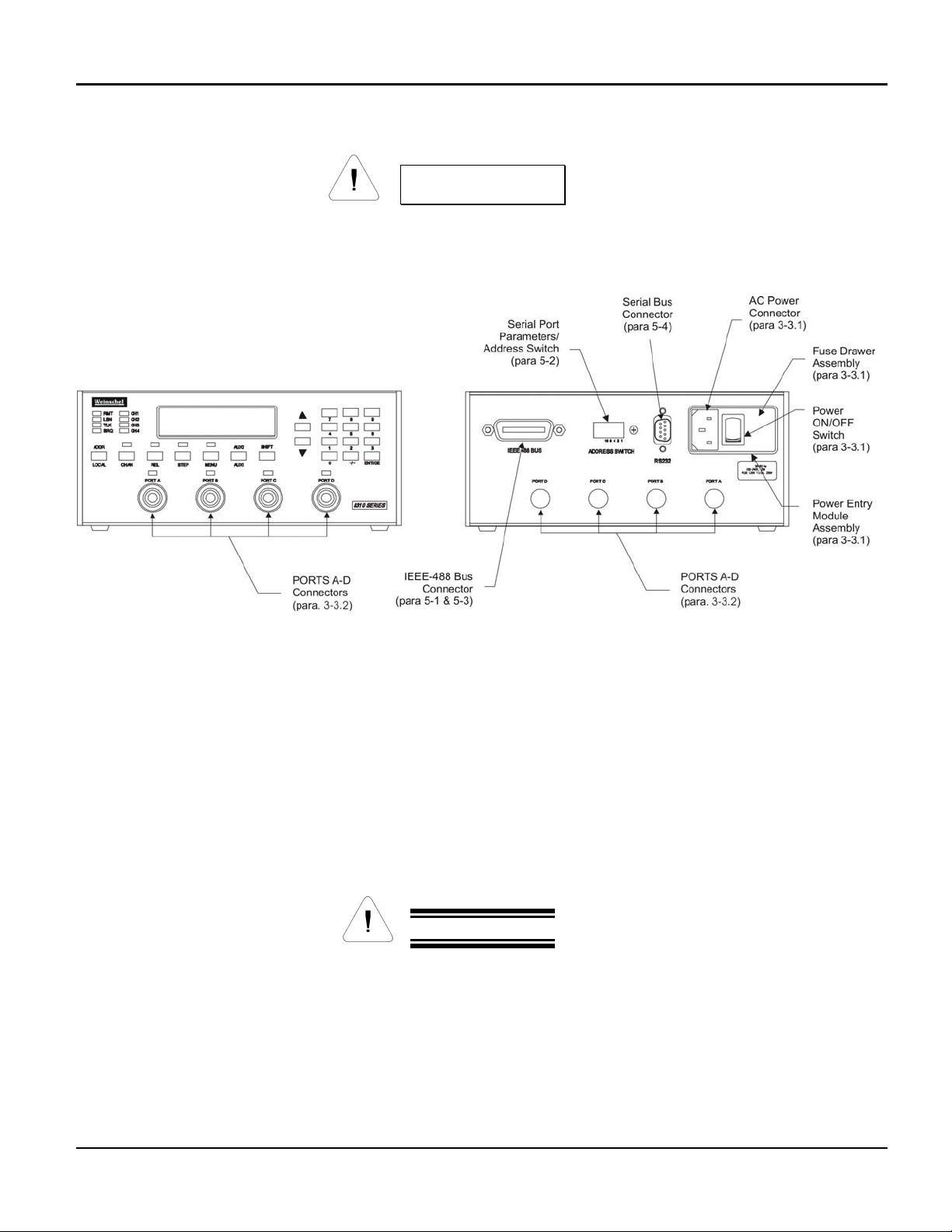
3-3 INPUT/OUTPUT OPTIONS: The following paragraphs provide a description of the connections that can be made
to the 8310 Series Attenuator Unit. Figure 1 shows the location of these connectors and switches.
WARNING
Sufficient power levels are present at the Power Input Assembly to cause personal injury.
Ensure that the instrument power cord is DISCONNECTED before attempting to change
fuses.
Figure 1. Front & Rear Panel Connectors
3-3.1 POWER ENTRY MODULE ASSEMBLY: The Power Entry Module Assembly located on the rear panel contains
a three-prong ac power input connector and a fuse drawer assembly (Figure 1). The Fuse Drawer Assembly
contains the line voltage fuse (Weinschel P/N 052-1-1.5). The Model 8310 uses a T 1.5A, 250 Vac fuse which is 5 x
20 mm in size. Refer to paragraph 8-4.1 for replacement of the fuse.
The AC Power Connector, located on the left side of XF1 (Figure 1), is a plug-type, prong insert connector with three
conductors for connection of the power cord (P/N 068-21) to the Power Supply Assembly located within the Attenuator
Unit. This connector also grounds the chassis of the Attenuator Unit when the ac power cord is connected to a
grounded wall outlet. If necessary, use a three prong to two prong adapter and connect the adapter’s ground lead to
the outlet plate retaining screw.
The Power ON/OFF Switch is located on the rear panel and in part of the Power Entry Module Assembly. Placing the
POWER ON/OFF switch in the ON position applies power to the instrument.
CAUTION
When applying an RF signal to the RF INPUT connector, DO NOT exceed the maximum allowable
power level specifications of the Model 8310.
3-3.2. PORTS A-D CONNECTORS: A typical 8310 Series Attenuator Unit contains 4 four standard D holes
on the front and rear panel allowing for single or multi-channel configurations. Standard Model 8310’s are
supplied with two PLANAR CROWN®Type N connectors that can be mounted on the front or rear panel.
These connectors provide a input and output port where various types of RF signals can be applied to the
devices internally mounted in the Model 8310 (Connector location specified by customer when ordering).
Some special configurations could contain Aeroflex / Weinschel’s Model 1568 SMA Panel Adapters or other
types of crowns (see accessories for other types).
Artisan Technology Group - Quality Instrumentation ... Guaranteed | (888) 88-SOURCE | www.artisantg.com

Model 8310 IM-289A
Aeroflex / Weinschel 12
NOTE
The use of the PLANAR CROWN®connectors provide the user with easy exchange of connector
types, which eliminates the need for adapters and other devices that would create additional insertion
loss. This type of connector also provides quick removal and replacement of defective connectors.
For more information about the PLANAR CROWN®connectors contact the Sales Department at
Aeroflex / Weinschel.
4. FRONT PANEL CONTROLS & INDICATORS:
The following paragraphs provide setup and general guidelines for operating the 8310 Series Programmable
Attenuator Unit and its different bus configurations. Also provided is a general description of the internal circuitry of the
8310.
Figure 2. 8310 Series Front Panel
ENTRY keys: The numeric entry keys allow the user to directly enter numeric values. When using
the keypad, values are not updated until the ENT (enter) key is pressed. The Minus (-) and CE (clear
entry) functions may be accessed via first depressing the SHIFT key.
INCR & DECR : The INCR and DECR keys allow settings to be scrolled from their current value.
Unlike the ENTRY keys, the new setting is updated immediately without the use of the ENT key.
CHAN: Allows the selection of the current channel, as indicated by the CH1-CH4 indicators.
Repeated depressions of the CHAN key will select the next available channel. The main display will
show the current setting of the channel.
REL: This key control allows the use of a relative mode for attenuators, as indicated by the REL
mode indicator. When turned on, the currently displayed attenuation value is used as a reference
value from which the attenuation may be set. In this mode, attenuation values may be positive or
negative from the reference setting. When REL is turned off, the display returns to the actual
attenuation setting for the channel.
STEP: This key allows the user to change the attenuation step size used by the INCR and DECR
keys. When turned on, as, indicated by the STEP indicator, the current step size is displayed in the
main display, and a new value may be entered using the INCR/DECR or ENTRY keys. The step size
may be set to any multiple of the intrinsic step size for the currently selected channel.
MENU: Invokes the menu functions. Menu selections may be made via the INCR and DECR keys.
(NOTE: menu functions are currently not implemented as of 3/8/99)
AUX1/AUX2: The function of these keys is user-programmable via remote operation. They invoke
any currently defined AUX1 and AUX2 macros. Refer to the macro programming section for
information on creating macro definitions.
LOCAL: This key places the 8310 in local operation mode, unless the key function has been
overridden via an IEEE-488.2 local lockout or execution of the LOCKOUT command.
ADDR: This key displays the current IEEE-488.2 address. The address may be changed from the
front-panel, however, the initial setting at power on is derived from the rear-panel address switch.
Artisan Technology Group - Quality Instrumentation ... Guaranteed | (888) 88-SOURCE | www.artisantg.com
Model 8310 IM-289A
Aeroflex / Weinschel 13
5. REMOTE OPERATION:
The following paragraphs provide setup and general guidelines for operating the Model 8310 using an
external controller.
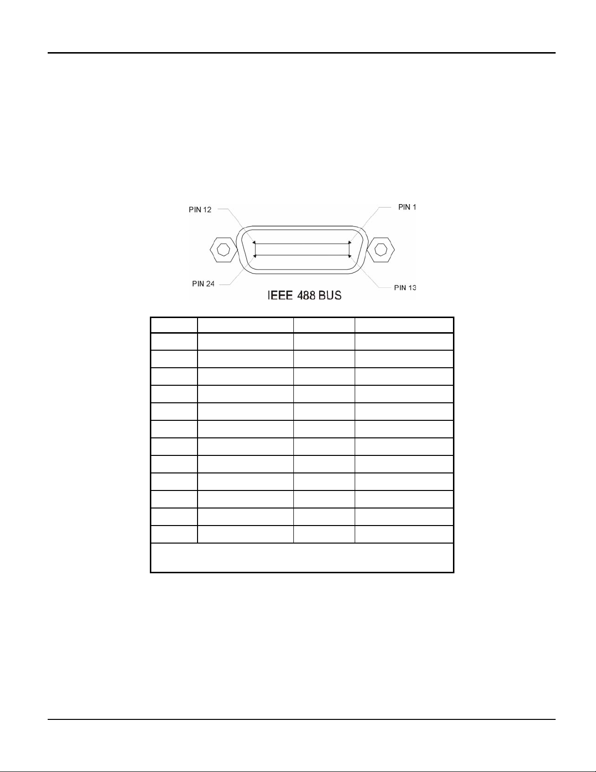
5-1. IEEE-488 INTERFACE BUS CONNECTOR: Joining the Model 8310-1 to a system controller requires the
connection of IEEE-488 control bus cable to the IEEE-488 INTERFACE BUS connector located on the rear panel.
Figure 3 shows the connector’s contact pin numbering scheme and lists the signal designator for signal present at
each contact pin.
PIN No. SIGNAL LINE PIN No. SIGNAL LINE
1 DIO 1 13 DIO 5
2 DIO 2 14 DIO 6
3 DIO 3 15 DIO 7
4 DIO 4 16 DIO 8
5 EOI (24)** 17 REN (24)**
6 DAV 18 GND (6)*
7 NRFD 19 GND (7)*
8 NDAC 20 GND (8)*
9 IFC 21 GND (9)*
10 SRQ 22 GND (10)*
11 ATN 23 GND (11)*
12 SHIELD 24 GND, LOGIC
* GND (N) refer to the signal ground return of the referenced pin.
** Return pin on pin 24.
Figure 3. IEEE-488 Interface Bus Pin Locations
5-2. GPIB ADDRESS/SERIAL COMMUNICATIONS SETTINGS: The GPIB Bus Address and Serial Communications
options are programmed via an internal 8 position DIP switch SW1 which is located on the rear panel. The switch is
shared between the two functions, with SW1-1 controlling the selection. When SW1-1 is OFF, the remaining switches
set the GPIB bus address. Likewise, when SW1-1 is ON, the switches are used to select the various serial options,
including baud rate, parity, and handshaking. Refer to Figure 4 for switch location.
Artisan Technology Group - Quality Instrumentation ... Guaranteed | (888) 88-SOURCE | www.artisantg.com

Model 8310 IM-289A
Aeroflex / Weinschel 14
To configure the IEEE-488 bus address or serial communications parameters, select the appropriate switch setting
using the tables located in below (Figure 4).
GPIB SW1 Serial Serial Parameters
SP 1 SP Mode Select
On = Serial parameters
Off = GPIB address
- - - 2 Echo Echo Echo Enable
On = Echo received data
Off = No echo
- - - 3 HndshkSel Handshaking Select
On = RTS/CTS
Off = XON/XOFF
A4 (16) 4 HndshkEna Handshake Enable
On = Enabled
Off = Disabled
A3 (8) 5 ParitySel Parity Select
On = Odd
Off = Even
A2 (4) 6 ParityEna Parity Enable
On = Enabled
Off = Disabled
A1 (2)
A0 (1)
7
8
BR1
BR2
BaudRate Select (see below)
BaudRate Select
BR1 BR0 RATE
0 0 2400
0 1 9600
1 0 19200
1 1 38400
Note: The GPIB Bus address is selectable from 0 to 30 via the rear
panel dip switch. This switch is factory set to 10.
IEEE-488 Address Truth Table
Switch Number 4 5 6 7 8
Decimal Weight 16 8 4 2 1
Address:
0
1
2
3
4
5
6
7
8
9
10
20
30
0
0
0
0
0
0
0
0
0
0
0
1
1
0
0
0
0
0
0
0
0
1
1
1
0
1
0
0
0
0
1
1
1
1
0
0
0
1
1
0
0
1
1
0
0
1
1
0
0
1
0
1
0
1
0
1
0
1
0
1
0
1
0
0
0
Figure 4. Internal Dip Switch
Artisan Technology Group - Quality Instrumentation ... Guaranteed | (888) 88-SOURCE | www.artisantg.com

Model 8310 IM-289A
Aeroflex / Weinschel 15
5-3. IEEE-488 (GPIB) Bus Operation
The internal functions of Model 8310 are controlled via an IEEE-488 bus and an external controller. The front
panel LSN and RMT indicators (Figure 2) are used as status indicators for the Model 8310 Programmable Interface’s
IEEE-488 bus operation. During bus operation a flashing LSN indicates that the Model 8310 is receiving. The RMT
indicator is illuminated when the Model 8310 is in the remote state.
The table below summarizes the IEEE-488.1 interface functions that are implemented by the Model 8310.
Interface Function Subset Description
Source Handshake SH1 Fully implemented
Acceptor
Handshake AH1 Fully implemented
Talker T6 All basic Talker functions
No extended addressing
Listener L4 All basic Listener functions.
No extended addressing
Service Request SR1 Fully implemented
Remote/Local RL1 Fully implemented
Parallel Poll PP0 No Parallel Poll Capability
Device Clear DC1 Fully implemented
Device Trigger DT0 No Trigger
Controller C0 No Controller Functions
Electrical Interface E2 All tri-state drivers
The GPIB interface of the 8310 is IEEE-488.2 compliant. The 8310 recognizes instructions and data sent via
the GPIB interface in the form of program messages comprised of ASCII characters. A program message is
comprised of a sequence of program message units separated by semicolons and terminated by a line terminator
(LINE END). A line terminator takes the form of an ASCII LF character (0AH), or an EOI signal asserted with the last
data byte, or both. The 8310 program message units may be divided into two syntax groups: commands and queries.
Refer to the section on command syntax for more information.
Artisan Technology Group - Quality Instrumentation ... Guaranteed | (888) 88-SOURCE | www.artisantg.com
Model 8310 IM-289A
Aeroflex / Weinschel 16
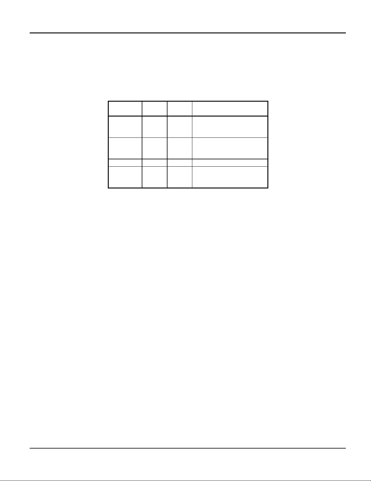
5-4. Serial Operation: The serial interface (RS232/RS422) provides a means of remotely programming the 8310 via
external computer. The 8310 provides for user-selectable communications parameters via a DIP switch (SW1),
including baud rate, data format, and handshaking method. LED indicators are provided for transmit (TX) and receive
(RX) activity. Selection between RS232/RS422 mode is controlled via an internal 4 position DIP switch SW2, which
also provides for user-selectable 120 ohm terminations for the RS422 receiver lines. The RS422 mode transceivers
are electrically compatible with RS485.
SW2 RS232 RS422
RS485 Description
1 OFF User
Select CTS Termination
On = Termination
Off = No Termination
2 OFF User
Select RXD Termination
On = Termination
Off = No Termination
3 OFF ON RI/RTS Select
4 ON OFF Serial Mode
On = RS232
Off = RS422
The data format includes a start bit, eight data bits, and one stop bit (N81). The Baud Rate may be set to
2400, 9600, 19200, or 34800. Parity selections include settings for None, Even, or Odd parity. Handshaking may be
enabled, if desired, and the method may be set to either hardware (RTS/CTS) or software (XON/XOFF). For
interactive terminal use, echoing may be enabled, in which the 8210A will echo all characters received back to the
terminal.
All data and commands are encoded using the ASCII character set. The syntax for commands is the same as
for GPIB operation, and uses the syntax structure defined by IEEE 488.2, with the exception of the command
termination rules. Commands sent to the 8210A may be terminated with either an ASCII CR (0x0D) or ASCII LF
(0x0A) character. By default, all responses from the 8210A are terminated in an ASCII CR/LF sequence (0x0D
followed by 0x0A).
Software handshaking uses the XON/XOFF scheme in which an ASCII DC3 (0x13) character is transmitted
by the receiver to indicate that data transmission should be halted (XOFF), and an ASCII DC1 (0x11) character is
transmitted to indicate that data transmission may continue (XON). Hardware handshaking utilizes the RTS and CTS
lines. When the RTS output signal is asserted true, the unit is ready for data. This signal should be connected to the
external computer's CTS input signal, so that when the receiver is ready, the transmitter may send data. When the
unit is not ready for data, it unasserts the RTS signal, halting data transmission. Likewise, the unit monitors the CTS
input signal during data transmission, halting transmission if the external computer unasserts it's RTS signal. In
addition, the 8310 unasserts the RTS signal while command execution is in progress.
For those systems incorporating local front panel controls, the serial port can lockout local users, providing a Remote/
Local function similar to that of GPIB operation.
Artisan Technology Group - Quality Instrumentation ... Guaranteed | (888) 88-SOURCE | www.artisantg.com

Model 8310 IM-289A
Aeroflex / Weinschel 17
5-4.1. RS-232 Operation: The RS-232 Serial port is a 9-pin connector that is compatible with the pin-out of the serial
port on a PC. It allows the use of a null-modem style cable. The pin-out for the connector is show below. For clarity,
the signal names and directions are relative to the 8310.
Pin Signal Name Description Direction
1 DCD unused ---
2 RxD Receive data input
3 TxD Transmit data output
4 DTR Signals DTE is on-line output
5 GND Ground ---
6 DSR unused ---
7 RTS Signals DTE is ready output
8 CTS Signals DCE is ready input
9 RI unused ---
The DTR signal is asserted when power is on, indicating that the unit is ready.
1
2
3
4
5
9
8
7
6DCD
RxD
TxD
DTR
GND
RI
CTS
RTS
DSR
RS232
9-pin DB9
Pinout
2
3
4
5
6
7
8
9
1
2
3
4
5
6
7
8
9
1
Null Modem Cable
Artisan Technology Group - Quality Instrumentation ... Guaranteed | (888) 88-SOURCE | www.artisantg.com
This manual suits for next models
66
Table of contents
Other Aeroflex Industrial Equipment manuals

Popular Industrial Equipment manuals by other brands


CommScope
CommScope 864 FDH RESKIN KIT installation instructions

Bosch
Bosch Rexroth HAB6-350-4X/2G07G-2N111-CE operating instructions

allfi
allfi Abrasive Feeder 2.0 Assembly, Operating and Maintenance Instruction

Delta Regis
Delta Regis ERGO15A Series Instructions for Use, Assembly and Maintenance

York
York HVQ 515 Installation and user manual

ABB
ABB HT578114 Operation manual