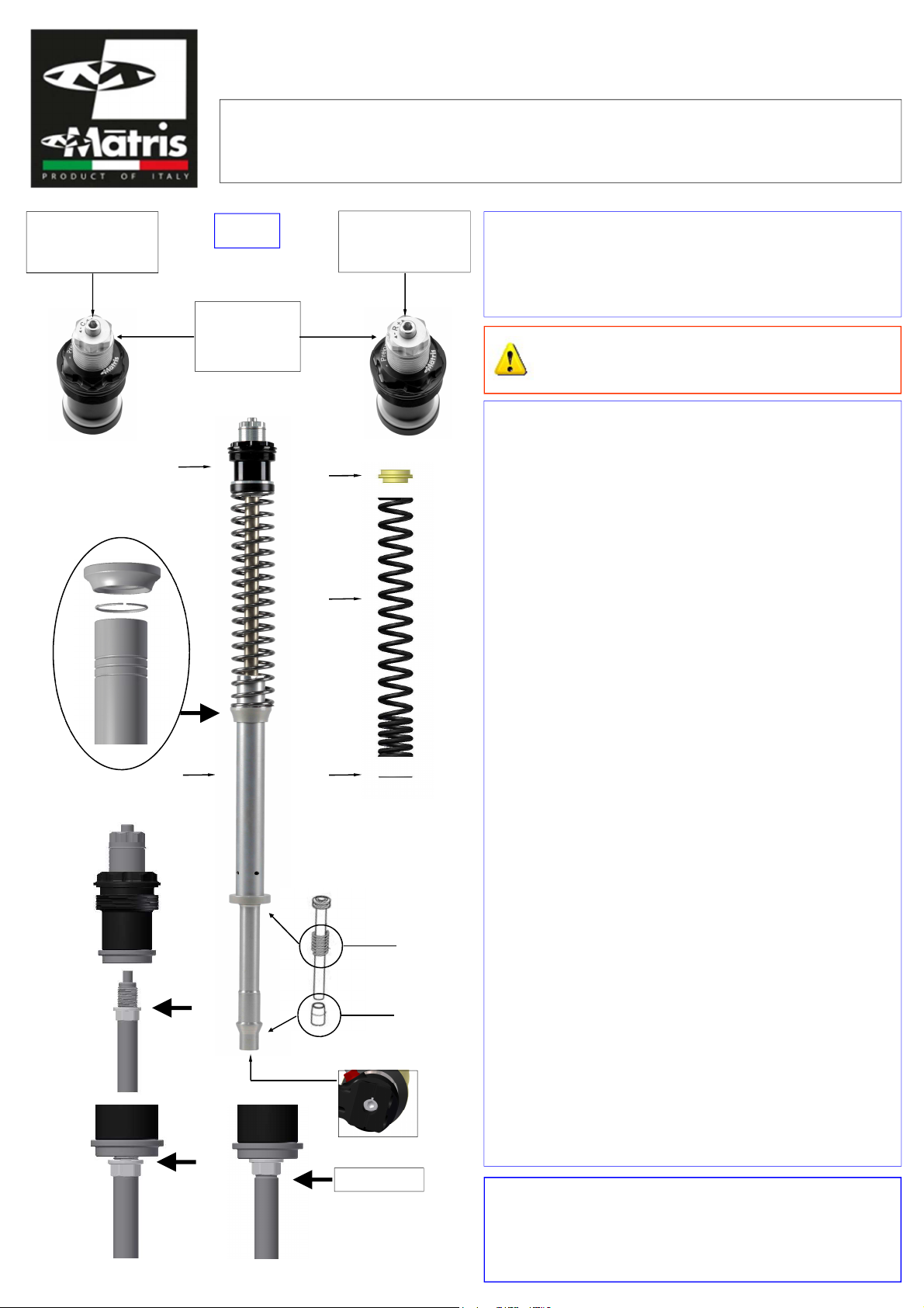
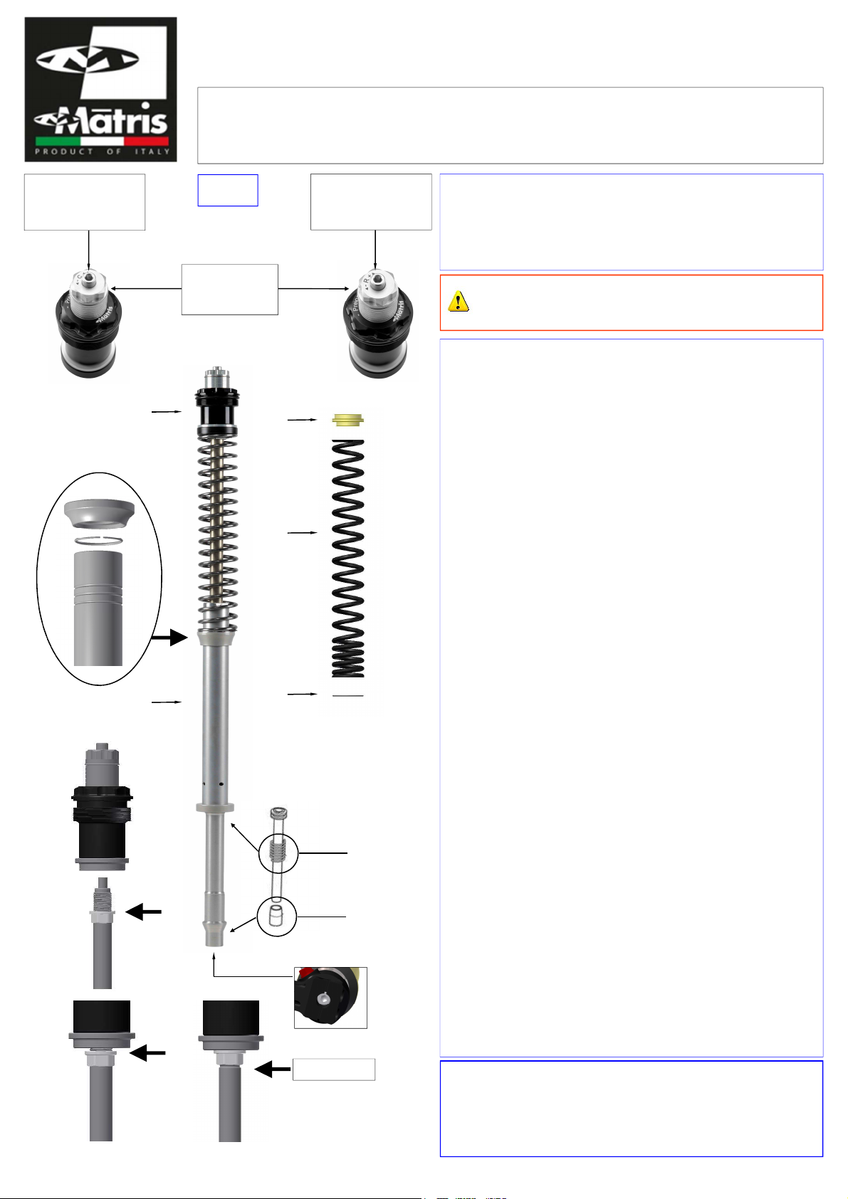
Matris F15K User manual

Componenti Kit
A– set tappo forcella B– distanziale
C– molla 36-320 D– cartuccia idraulica D.20
E– rondella molla Motorex Fork il SAE 5 W (1l)
PROCEDURA DI MONTAGGIO
1- Rimuovere la forcella dalla moto e smontare il kit forcella
originale.
2- Pulire bene fodero, canna forcella e piedino facendo
attenzione a non rovinare paraolio e boccole di
scorrimento.
3- Rimontare boccole e paraolio sul fodero, ingrassando
bene le parti sottoposte a scorrimento.
4- Mantenere la contro molla originale (rif.6) e il fondo
corsa (hydro-stop) originale (rif.7).
5- Posizionale il kit cartuccia “D” all’interno della forcella,
facendo attenzione sia ben posizionato nella sua sede.
6- Fissare la vite inferiore (rif.1) e assicurarsi che il kit
sia perfettamente in posizione.
Per le coppie di serraggio delle viti seguire il manuale
di officina.
PROCEDURA DI SPURGO
1- Riempire poco a poco la forcella con l’olio.
Fare confluire l’olio all’interno della cartuccia.
Eliminare eventuali vuoti d’aria che si creano in essa
muovendo ripetutamente e lentamente l’asta su e giù.
2- Stabilire il livello dell’olio come consigliato (cheda setup).
Not : Il livello dell’olio va portato a misura senza la
molla, con l’asta pompante a fine corsa (tutta in giù)
e la canna o il fodero tutto giù.
3- Posizionare in sequenza i seguenti componenti del kit:
- “E” rondella molla
- “C” molla (Not : prima dell’assemblaggio, togliere il
protettivo, pulendo e sgrassando bene la molla).
- “B” distanziale
4- Portare l’asta pompante in massima estensione.
5- Verificare che il dado di blocco su stelo sia in posizione
tutto avvitato (rif.3) e le regolazioni di Precarico molla e
Compressione/Estensione in posizione tutto aperto.
Avvitare l’asta pompante al tappo, completamente fino
alla battuta (rif.4)
Bloccare il dado al tappo forcella (rif.5)
(coppia di serraggio 10Nm)
6- Avvitare il tappo forcella al fodero facendo attenzione
a non danneggiare l’ Ring del tappo forcella.
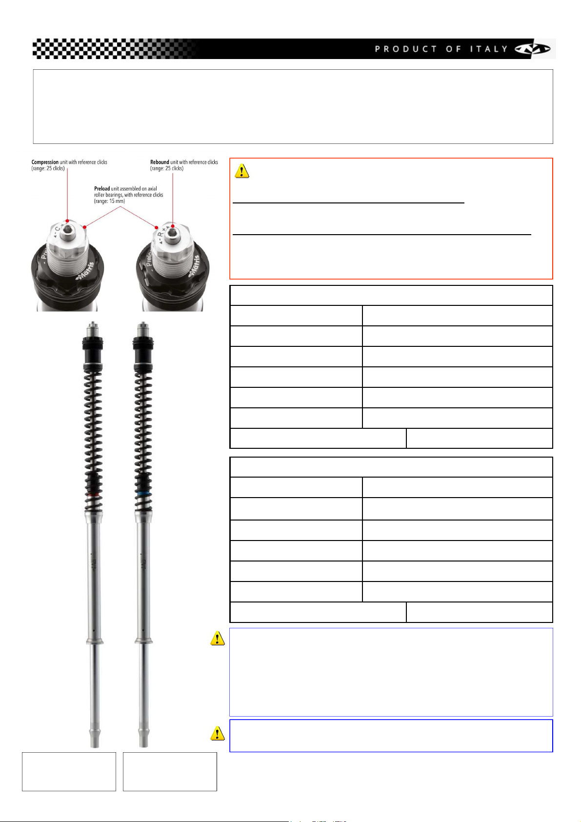
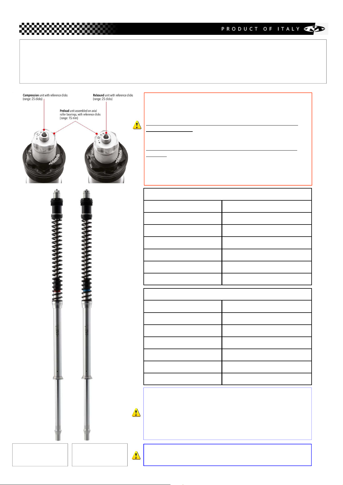
PRECARIC
M LLA
(chiave 19)
Regolazione
C MPRESSI NE “C”
(chiave 4)
Regolazione
ESTENSI NE “R”
(chiave 4)
ATTENZIONE (rif.2)
Il ferma molla viene fornito nella posizione centrale.
L’anello di blocco può essere spostato nella sede inferiore
o superiore con una variazione del precarico iniziale della
molla di –4 mm / +4 mm
C
A
E
D
B
Rif.2
Rif.3
Rif.5
Rif.4
F15R100K - F15K “quad valve” fork kit
Roy l Enfield Interceptor 650 my19
ITA
M tris srl
Vi Industri le 12 - 36043 C mis no Vicentino (VI) - It ly
tel +39 (0)444 411636 - f x +39 (0)444 411887 - info@m trisd mpers.com - www.m trisd mpers.com
ATTENZIONE
Per lo smont ggio dell forcell e le coppie di
serr ggio delle viti, seguire il m nu le di officin
(chiave 16)
Rif.1
Rif.7
Rif.6

TARATURE DI RIFERIMENTO CONSIGLIATE
Reg. Estensione 15 Click
Reg. Compressione 15 Click
Costante molla
Precarico molla 6 giri
Livello olio 15 mm
Corsa come originale
Altezza da piastra superiore
8.5 N/mm
TARATURA - STEP 2
Reg. Estensione Click
Reg. Compressione Click
Costante elastica molla
Precarico molla giri / linee
Livello olio
Corsa
Altezza da piastra superiore
N/mm
Regol zione COMPRESSIONE & ESTENSIONE
I click di riferimento per estensione e compressione vanno contati
da tutto chiuso agendo in senso antiorario
Regol zione PRECARICO MOLLA
Da tutto aperto, girare in senso orario
1 giro = 1 mm / 1 line = 2 mm
Il kit è consegnato pronto per il montaggio.
Per evitare danni ai componenti della forcella, effettuare tutte
le regolazioni a kit e forcella montati.
Non agire sulle regolazioni a forcella e tappi smontati.
Assicurarsi sempre che le regolazioni siano in posizione tutto aperto
(Estensione & Compressione) e tutto scarico per Precarico molla.
Le regolazioni e tarature devono essere effettuate a forcella montata.
- Forcella SINISTRA = Regolazione COMPRESSIONE
- Forcella DESTRA = Regolazione ESTENSIONE
Interventi tecnici per manutenzione e/o modifica del prodotto devono
essere fatti da Matris srl o Centro Assistenza Autorizzato.
nello BLU
l to destro
ESTENSIONE
nello ROSSO
l to sinistro
COMPRESSIONE
F15R100K - F15K “quad valve” fork kit
Roy l Enfield Interceptor 650 my19
(fork type Kayaba)

ASSEMBLY INSTRUCTIONS
1- Remove the front forks from the bike and remove
the original internal fork kit.
2- Thoroughly clean sleeve, fork tube and bottom avoiding
all damages to oil seals and guide bushings
3- Re-assemble bushings and oil seals on the sleeve
and add grease to all sliding parts.
4- Keep the original Top-ut-Spring (ref.6) and the
original bottom End-Stroke (hydro-stop) (ref.7).
5- Position the fork kit “D” inside the fork tube.
Make sure it is firmly on its bottom base.
6- Tighten the lower screw (ref.1) and make sure the
fork kit lines up perfectly inside the fork tube.
Note: for the tightening torques, follow the service
manual.
AIR BLEEDING INSTRUCTIONS
1- Slowly pour oil into the fork so that it flows inside the
cartridge.
Slide the rod up and down several times to bleed any
air bubbles out of the cartridge.
2- Adjust the oil level according to the setup card.
Note: the oil level must be measured without spring
and the rod pushed completely down.
3- Position the fork kit parts as following:
- “E” spring washer
- “C” spring (Note: before assembly, remove the
protective, cleaning and degreasing well the spring)
- “B” spring spacer
4- Take the pumping rod to the maximum extention.
5- (ref.3) Check that the locking nut on the shaft is in the
all screwed position and make sure that the adjustments
of Compression / Rebound are in the full open position
and the spring preload aduste full unloading.
(ref.4) Screw the cap to the damper rod completely
up the stop.
(ref.5) Tighten the nut to the fork cap.
(Spanner 16 / Torque load 10 Nm)
6- Screw the fork cap onto the fork tube (make sure you
do not damage the -ring placed on the fork cap).
FORK KIT PARTS
A- Fork cap unit B- Spring spacer
C- Spring 36-320 D- Hydraulic cartridge
E- Spring washer Motorex Fork il SAE 5 W
C MPRESSI N
ADJUSTMENT “C”
(tool 4)
REB UND
ADJUSTMENT “R”
(tool 4)
ATTENTION
To remove the fork nd tightening torques,
follow the service m nu l
ATTENTION (ref 2)
The stop spring is supplied at the center position.
The locking ring can be moved in the lower or upper seat
with a variation of the initial spring preload.
(decrease of -4 mm / increase of +4 mm)
C
A
ED
B
Ref.2
Ref.3
Ref.5
Ref.4
ENG
M tris srl
Vi Industri le 12 - 36043 C mis no Vicentino (VI) - It ly
tel +39 (0)444 411636 - f x +39 (0)444 411887 - info@m trisd mpers.com - www.m trisd mpers.com
(tool 16)
Rif.1
Rif.7
Rif.6
SPRING
PREL ADING
ADJUSTER
(tool 19)
F15R100K - F15K “quad valve” fork kit
Roy l Enfield Interceptor 650 my19

RECOMMENDED ADJUSTMENT SETUP
Rebound adjustment 15 Click
Compression adjustment 15 Click
Spring rate 8.5 N/mm
Spring preload 6 turns
il level 15 mm
Stroke as original one
Heigh from top plate mm
ADJUSTMENT STEP 2
Rebound adjustment Click
Compression adjustment Click
Spring rate N/mm
Spring preload turns
il level mm mm
Stroke mm as original one
Heigh from top plate mm
N/mm
COMPRESSION & REBOUND djustment
To count the rebound and compression clicks:
from fully closed, turn anticlockwise
SPRING PRELOAD djustment
from fully open, turn clockwise
1 turn = 1 mm / 1 line = 2 mm
The fork kit parts are supplied ready to fit.
During assembling and fitting the fork kit, to avoid damage
to the fork components, make all adjustments with the fork kit
mounted on the fork.
Not act on the adjustments when the fork caps or cartridges
are disassembled.
Make sure that the settings are in the full open position
(Compression & Rebound) and full unloading (Spring Preload).
All adjustments must be made with all components fitted on
the fork.
- Left fork = COMPRESSION adj.
- Right Fork = REBOUND adj.
All technical interventions for maintenance and/or modification of the
product must be performed by Matris Company or a Matris authorized
service center.
BLU ring
right side
REBOUND
RED ring
left side
COMPRESSION
F15R100K - F15K “quad valve” fork kit
Roy l Enfield Interceptor 650 my19
(fork type Kayaba)
This manual suits for next models
1
Table of contents
Languages: