Matrix Fitness C5x-03 User manual

C5x-03 Climb mill
SERVICE MANUAL

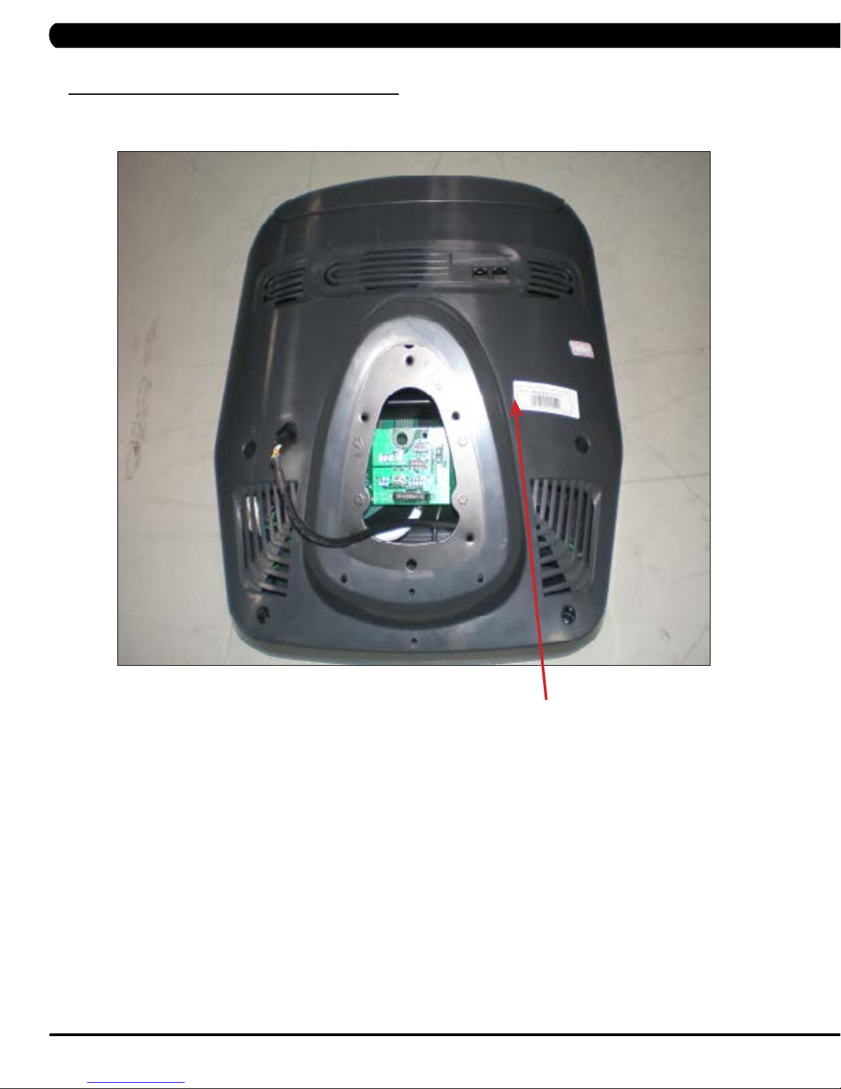
CHAPTER 1: SERIAL NUMBER LOCATION ........................................................... 1
CHAPTER 2: IMPORTANT SAFETY INSTRUCTIONS
2.1 Read and Save These Instructions............................................................................. 3
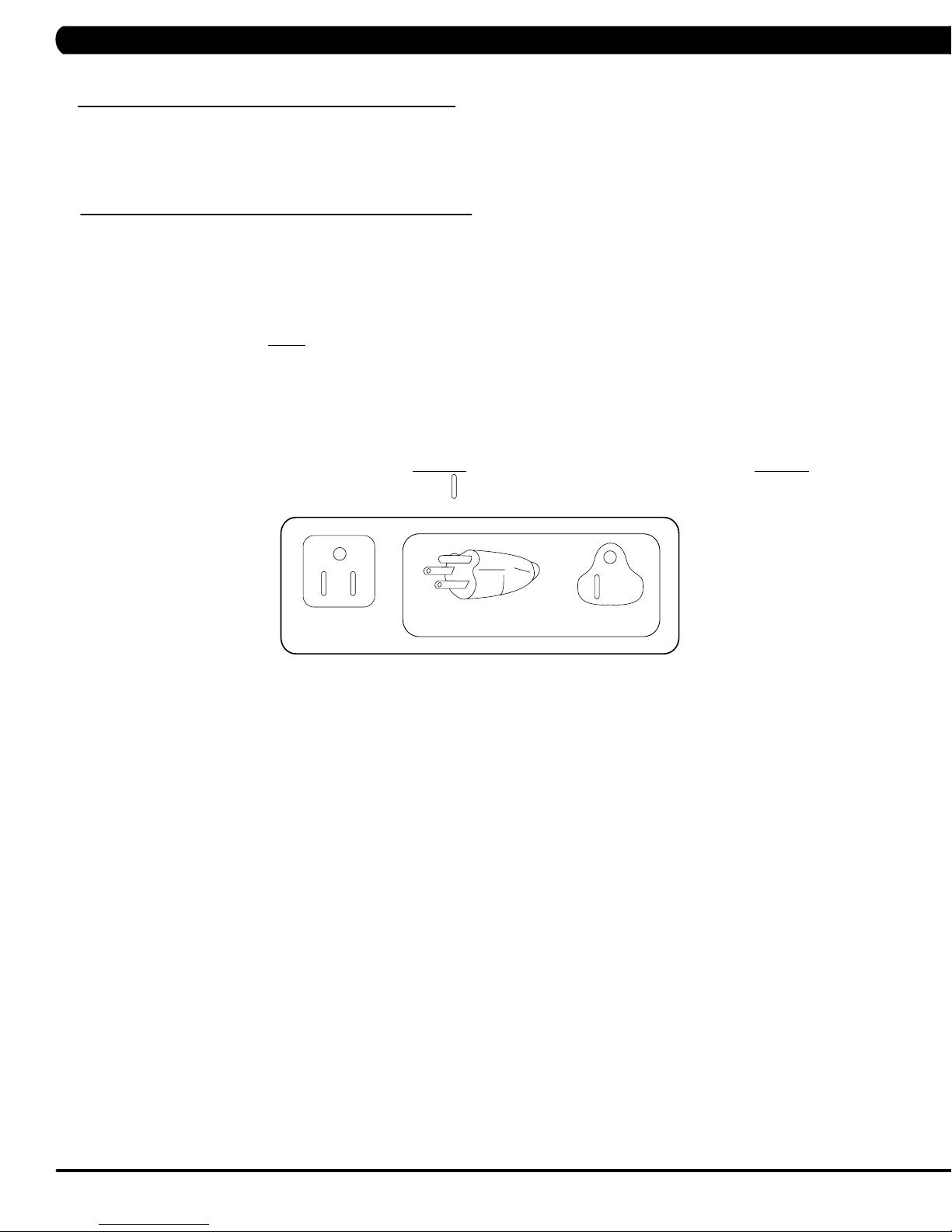
2.2 Electrical Requirements ............................................................................................. 4
2.3 Locating the Unit ......................................................................................................... 5
CHAPTER 3: PREVENTATIVE MAINTENANCE
3.1 Recommended Cleaning Tips .................................................................................... 6
3.2 Care and Maintenance Instructions ........................................................................... 7
CHAPTER 4: CONSOLE OVERLAY AND WORKOUT DESCRIPTION
4.1 Console Description ................................................................................................... 8
4.2 Workout Setup Steps ................................................................................................. 9
CHAPTER 5: MANAGER MODE
5.1 Using Manager Mode.................................................................................................. 10
5.2 Manager Mode Overview............................................................................................ 11
CHAPTER 6: ENGINEERING MODE
6.1 Using Engineering Mode............................................................................................. 12
CHAPTER 7: SERVICE MODE
7.1 Using Service Mode.................................................................................................... 13
CHAPTER 8: TROUBLESHOOTING
8.1 Electrical Diagram ...................................................................................................... 14
8.2 LCB Error Indicators .................................................................................................. 21
8.3 Error Code Troubleshooting - 01AC ........................................................................... 23
8.4 Error Code Troubleshooting - 01AF............................................................................ 24
8.5 Error Code Troubleshooting - 02A0 ........................................................................... 25
8.6 Error Code Troubleshooting - 02BE / 04BF................................................................ 26
8.7 Error Code Troubleshooting - 02C0............................................................................ 27
8.8 Error Code Troubleshooting - 02C1............................................................................ 28
8.9 Error Code Troubleshooting - 04A0 ............................................................................ 29
8.10 Error Code Troubleshooting - 04B0 ............................................................................ 30
8.11 Troubleshooting - No Power to the Console............................................................... 31
8.12 Troubleshooting - Heart Rate Issues .......................................................................... 32
8.13 Troubleshooting - Toggle Issues ................................................................................. 35
CHAPTER 9: PART REPLACEMENT GUIDE
9.1 Side Cover Replacement ........................................................................................... 38
9.2 Console Replacement................................................................................................. 40
9.3 Console Overlay / Keypad Replacement.................................................................... 41
9.4 Front Shroud Replacement......................................................................................... 43
9.5 Lower Control Board (LCB) Replacement .................................................................. 45
9.6 Upper Handlebar Replacement .................................................................................. 46
9.7 Lower Handlebar Replacement .................................................................................. 48
9.8 Handlebar Service....................................................................................................... 49
9.9 Stair Replacement....................................................................................................... 50
9.10 Drive Set Replacement ............................................................................................... 52
9.11 Chain Replacement..................................................................................................... 54
9.12 Brake Replacement..................................................................................................... 56
9.13 Fan Replacement........................................................................................................ 57
9.14 ECB Belt Replacement ............................................................................................... 58
9.15 Drive Belt Replacement .............................................................................................. 59
9.16 ECB Replacement....................................................................................................... 60
TABLE OF CONTENTS

III
9.17 Speed Sensor Replacement ....................................................................................... 62
9.18 Control Zone Replacement ......................................................................................... 63
9.19 Proximity Sensor Replacement................................................................................... 64
9.20 Testing the Climb Mill.................................................................................................. 65
CHAPTER 10: CLIMB MILL SPECIFICATIONS AND ASSEMBLY GUIDE
10.1 Climb Mill Specifications ............................................................................................ 66
10.2 Assembly Hardware .................................................................................................... 67
10.3 Climb Mill Assembly Steps ......................................................................................... 68
10.4 Stabilizing the Climb Mill ............................................................................................. 72
10.5 MYE TV Bracket Installation Instructions.................................................................... 73
10.6 PCTV Bracket Installation Instructions........................................................................ 79
CHAPTER 11: SOFTWARE UPGRADE PROCEDURE
11.1 Software Upgrade Procedure ..................................................................................... 84
TABLE OF CONTENTS

1
1.1 SERIAL NUMBER LOCATION
CHAPTER 1: SERIAL NUMBER LOCATION
SERIAL NUMBER LOCATION

2
Console serial number loCation
1.1 SERIAL NUMBER LOCATION - CONTINUED
CONSOLE SERIAL NUMBER LOCATION
CHAPTER 1: SERIAL NUMBER LOCATION

3
This Climb Mill is intended for commercial use. To ensure your safety
and protect the equipment, read all instructions before operating the
MATRIX Climb Mill.
When using an electrical product, basic precautions should always be
followed including the following:
• Anapplianceshouldneverbeleftunattendedwhenplugged
in. Unplugtheunitfromtheoutletwhennotinuseandbefore
puttingonortakingoffanyparts.
• Thisproductmustbeusedforitsintendedpurpose
describedinthisservicemanual. Donotuseother
attachmentsthatarenotrecommendbythemanufacturer.
Attachmentsmaycauseinjury.
• Topreventelectricalshock,neverdroporinsertanyobject
intoanyopening.
• Donotremovethesidecovers.Serviceshouldonlybedone
byanauthorizedservicetechnician.
• Neveroperatetheunitwiththeairopeningblocked.Keep
theairopeningclean,freeoflintandhair.
• Neveroperatetheunitifithasadamagedcordorplug,ifit
isnotworkingproperly,ifithasbeendamaged,orimmersed
inwater.
• Closesupervisionisnecessarywhentheunitisusedbyor
nearchildrenordisablepersons.
• Donotuseoutdoors.
• Donotoperatewhereaerosol(spray)productsarebeing
usedorwhenoxygenisbeingadministered.
• Donotusetheequipmentinanywayotherthandesignedor
intendedbythemanufacturer.ItisimperativethatallMatrix
FitnessSystemsequipmentisusedproperlytoavoidinjury.
• Keephandsandfeetclearofmovingpartsatalltimesto
avoidinjury.
• Unsupervisedchildrenmustbekeptawayfromthisequip
ment.
• Donotwearlooseclothingwhileontheequipment.
*AtNOtimeshouldpetsorchildrenundertheageof13be
closertotheunitthan10feet.
CAUTION! Ifyouexperiencechestpains,nausea,dizziness,or
shortnessofbreath,stopexercisingimmediatelyandconsult
yourphysicianbeforecontinuing.
CAUTION! Anychangesormodificationstothisequipment
couldvoidtheproductwarranty.
2.1 READ AND SAVE THESE INSTRUCTIONS
CHAPTER 2: IMPORTANT SAFETY INSTRUCTIONS

4
2.2 ELECTRICAL REQUIREMENTS
MATRIX DEDICATED CIRCUIT/ELECTRICAL REQUIREMENT INFO
All Matrix Climb Mills require the use of a 15 amp or 20 amp “dedicated circuit,” with a non-looped (isolated) neutral/ground, for the power
requirement. Quite simply this means that each outlet you plug Climb Mills into should not have anything else running on that same circuit besides
other Climb Mills (up to 3 per 15 amp circuit and 4 per 20 amp circuit). The easiest way to verify this is to locate the main circuit breaker box, and
turn off the breaker(s) one at a time. Once a breaker has been turned off, the only thing that should not have power to it are the Climb Mills in
question. No lamps, vending machines, fans, sound systems, or any other item should lose power when you perform this test.
Non-looped (isolated) neutral/grounding means that each circuit must have an individual neutral/ground connection coming from it, and terminating
at an approved earth ground. You cannot “jumper” a single neutral/ground from one circuit to the next.
In addition to the dedicated circuit requirement, the proper gauge wire must be used from the circuit breaker box, to each outlet that will have the
maximum number of units running off of it. If the distance from the circuit breaker box, to each outlet, is 100 ft or less, then 12 gauge wire may be
used. For any distance greater than 100 ft from the circuit breaker box to the outlet, 10 gauge wire must be used.
For your safety and Climb Mill performance, the ground on this circuit must be non-looped. Please refer to NEC article 210-21 and 210-23. Your Climb
Mill is provided with a power cord with a plug listed below and requires the listed outlet. Any alterations of this power cord could void all warranties
for this product. Multiple Climb Mills can be powered on one dedicated circuit. (3 units per 15 Amp and 4 units per 20 Amp dedicated circuit.)
GROUNDING INSTRUCTIONS:
The Matrix Climb Mill must be grounded. If it should malfunction or break down, grounding provides a path of least resistance for electric
current to reduce the risk of electric shock. The Climb Mill is equipped with a cord having an equipment grounding conductor and a grounding
plug. The plug must be plugged into an appropriate outlet that is properly installed and grounded in accordance with all local codes and
ordinances. If the user does not follow these grounding instructions, the user could void the Matrix limited warranty.
DANGER: Improper connection of the equipment grounding conductor can result in the risk of electric shock. Check with a qualified electrician
if the user is in doubt as to whether the product is properly grounded. Do not modify the plug provided with the product if it will not fit the outlet,
have a proper outlet installed by an electrician
CHAPTER 2: IMPORTANT SAFETY INSTRUCTIONS
The Matrix Climb Mill must be AC powered. The Climb Mill is capable of being daisy chained together (up to 3 units per dedicated 15 amp
circuit) using a Matrix provided daisy chain (sold separately). Any alterations to the standard Matrix power cord will void all warranties.

5
2.3 LOCATING THE UNIT
CHAPTER 2: IMPORTANT SAFETY INSTRUCTIONS
LOCATION OF THE UNIT:
Place the unit on a level surface and away from direct sun light. The intense UV light can cause discoloration of plastics. Locate in an area
with cool temperatures and low humidity. Leave a clear zone behind the unit of at least 24". This zone must be clear of any obstruction and
allow the user a clear exit path from the unit. Do not place the unit in any area that will block the openings or vents. The unit should not be
used in a garage or covered patio.
HeightRequirements - The Climb Mill adds 30" - 38" (76 - 96cm) to a user's height. For example, a 6' (183cm) tall user will be 7'8"
(234.4cm - 254.4cm) off the floor. Total height of the user on the Climb Mill should not exceed 9'10" (300 cm), which means that users taller
than 6'8" (204cm) should not use this equipment.

6
3.1 RECOMMENDED CLEANING TIPS
CHAPTER 3: PREVENTATIVE MAINTENANCE
In order to maximize life span, and minimize down time, all Matrix Fitness Equipment requires regularly
scheduled cleaning.
YOU WILL NEED:
- Mild dish soap and water mixture in a spray bottle (10:1 water to soap ratio).
- Lint free 100% cotton cleaning cloths or Micro fiber cleaning cloths.
- Vacuum / Shop Vac with extendable hose and soft brush attachment.
- iPod corrosion blocker - Available from Matrix (part # ZMS4001374).
- Super Lube Multi Purpose Synthetic Lubricant with Syncolon® (PTFE) Aerosol - www.super-lube.com/sythetic-aerosol-spray-ezp-46.html.
- Corrosion Block (available from Matrix - part # ZMS4001374).
DAILY or as needed:
1. Empty the dust tray under the stairs and under the unit (Figure A). If you need to move the unit, unplug it first.
WEEKLY:
1. With a clean dry 100% lint free cloth and water / soap mixture, wipe down the entire frame including the stairs so it is free of dust, dirt, and
sweat.
2. With a clean dry 100% lint free cloth and water / soap mixture, wipe down the entire console area including the hand grips and hand rails.
MONTHLY:
1. Vacuum under and around the Climb Mill If you need to move the unit, unplug it first. Make sure to reset the casters after moving the unit
back into position to stabilize the unit.
2. Apply corrosion block to the metal part of the iPod cable.
QUARTERLY:
1. Remove the side access panels and vacuum out the inside of the unit (Figure B).
FIGURE A FIGURE B

7
3.2 CARE AND MAINTENANCE INSTRUCTION
In order to maximize life span, and minimize down time, all MATRIX equipment requires regular cleaning, and maintenance items performed on
a scheduled basis. This section contains detailed instructions on how to perform these items, the frequency of which they should be done, and a
check list to sign off each time service is completed for a specific machine. Some basic tools and supplies will be necessary to perform these tasks
which include (but may not be limited to):
* Metric Allen wrenches
* #2 Phillips head screwdriver
* Adjustable wrench
* Teflon based spray lubricant such as “Super Lube”, or other Matrix approved product
You may periodically see addendums to this document, as the Matrix Technical Support Team identifies items that require specific attention, the
latest version will always be available on the Matrix website, www.matrixfitness.com
DAILY MAINTENANCE ITEMS
1. Attempt to wobble the unit from side to side and front to back. Level the unit if needed (See Section 10.4).
QUARTERLY MAINTENANCE ITEMS
1. Check all connecting joint areas for tightness of fastened assemblies.
2. Remove the maintenance cover and check the fans for function. Also clean and remove any debris from the digital speed sensor.
3. Remove the maintenance cover and check the chains for damage, alignment and proper tension.
4. On units with a Control Zone, check to ensure the CZ is working properly by walking on the unit, then stepping on the CZ. The unit should stop
similar to an emergency stop on a treadmill.
CHAPTER 3: PREVENTATIVE MAINTENANCE

8
C5X CONSOLE DESCRIPTION
WORKOUTKEYS: Simple program view and selection buttons.
GO: One touch start.
ENTER: To confirm each program setting.
uP / DoWn leVel: Easy information and level selection.
UP/DOWNTIME: Easy information and time adjustment.
stoP: Ends workout and shows workout summary data.
NUMBERKEYPAD: Workout data input for workout setup. Level adjustment during workout.
COOLDOWN: Puts the Climb Mill into Cool Down Mode.
FAN: Allows for fan speed selection (fan has 3 operating speeds).
TOGGLEDISPLAY: Changes information displayed from top row to bottom one.
LANGUAGE: Select language.
4.1 CONSOLE DESCRIPTION
CHAPTER 4: CONSOLE OVERLAY AND WORKOUT DESCRIPTION

9
To set up a workout, choose the program wanted, then press ENTER.
Follow the prompts to begin your workout.
Go - Press to immediately begin a workout. Workout, resistance level,
and time will automatically go to default settings. All energy expenditure
values will be calculated using the default weight measurement.
manual - Manual allows the user to input more information while
defining their own workout. Calorie expenditure will be more accurate
when inputting information in Manual than by pressing GO.
rollinG Hills - The Rolling Hills program is a level based
program that automatically adjusts the resistance level to simulate real
terrain.
interVals - The Intervals program is a level based program that
automatically adjusts the resistance of the machine from low to high
intensity settings at regular intervals to burn calories.
Goal traininG - The Goal Training program is designed to help
users burn a target number of calories.
Calorie traininG - The Calorie Training program is designed
to help users burn a target number of calories.
Constant Watts - The Constant Watts program allows
you to vary your cadence or SPM and the machine's resistance will
adjust according to your selected goal. The quicker you step, the less
resistance for the goal selected.
Fat burn - The Fat Burn program is a level based workout that is
designed to help users burn fat through various resistance changes.
tarGet Heart rate - The Matrix Climb Mill comes with
standard digital contact heart rate sensors and are POLAR telemetry
compatible. The heart rate control workout mode allows the user
to program their desired heart rate zone, and the Climb Mill will
automatically adjust the level based upon the user's heart rate. The
heart rate zone is calculated using the following equation: (220-Age)*% =
target heart rate zone. The user must wear a POLAR telemetric strap or
continually hold onto the contact heart rate grips for this workout.
Locate the metal sensors on the handlebars of the Climb Mill. Notice
that there are two separate pieces of metal on each grip. You must be
making contact with both pieces of each grip to get an accurate heart
rate reading. You can grab these sensors in any program to view your
current heart rate.
FITNESSTEST(WFI) - The WFI (Wellness Fitness Initiative)
protocol is a test used by firefighters in a series of intervals lasting a
maximum of 16 minutes, where the speed is increased every minute
until the Target Heart Rate is exceeded for 15 seconds. When the
test is complete, the display provides a summary of V)2max, Highest
SPM, Elapsed Time, and Target Heart Rate. The test requires constant
monitoring of the user's heart rate, so the use of a telemetric heart rate
strap is highly recommended.
CPAT
The Candidate Physical Ability Test (CPAT) is a new minimum requirement
for the position of Firefighter. The job of a Firefighter is one of the most
physically demanding jobs in North America. Participants wear a 50-pound
(22.68-kg) vest to simulate the weight of self-contained breathing
apparatus (SCBA) and firefighter protective clothing. An additional 25
pounds (11.34 kg), using two 12.5-pound (5.67-kg) weights that simulate
a high-rise pack (hose bundle), is added to your shoulders for the stair
climb event. The candidate must maintain 60 SPM (steps per minute) for
3 minutes.
FITNESSTEST(SUBMAXIMAL)- The Submaximal test
measures cardiovascular fitness and provides an estimated Sub-maximal
VO2 max result. This assessment is a 4 stage test lasting 3-5 minutes
where the speed is increased until your Heart Rate is between 115 - 150
bpm for 2 of the stages. When the test is complete, a Fitness Rating is
displayed as High, Good, Average, Fair, or Low along with your age and
VO2 max. The test requires constant monitoring of the user's heart rate,
so the use of a telemetric heart rate strap is highly recommended.
FITNESS RATING NORMS (V02 MAX)
AGE 20-29 30-39 40-49 50-59 60+
MEN
HIGH 51.4+ 50.4+ 48.2+ 45.3 42.5+
GOOD 51.3-46.8 50.3-44.6 48.1-41.8 45.2-38.5 42.4-35.3
AVERAGE 46.7-42.5 44.5-41.0 41.7-38.1 38.4-35.2 35.2-31.8
FAIR 42.4-39.5 40.9-37.4 38.0-35.1 35.1-32.3 31.7-28.7
LOW 39.4 OR
LESS
37.3 OR
LESS
35.0 OR
LESS
32.2 OR
LESS
28.6 OR
LESS
WOMEN
HIGH 44.2+ 41.0+ 39.5+ 35.2+ 35.2
GOOD 44.1-38.1 40.9-36.7 39.4-33.8 35.1-30.9 35.1-29.4
AVERAGE 38.0-35.2 36.6-33.8 33.7-30.9 30.8-28.2 29.3-25.8
FAIR 35.1-32.3 33.7-30.5 30.8-28.3 28.1-25.5 25.7-23.8
LOW 32.2 OR
LESS
30.4 OR
LESS
28.2 OR
LESS
25.4 OR
LESS
23.7 OR
LESS
4.2 WORKOUT SETUP STEPS
CHAPTER 4: CONSOLE OVERLAY AND WORKOUT DESCRIPTION

10
5.1 USING MANAGER MODE
CHAPTER 5: MANAGER MODE
The Manager's Custom Mode allows the club owner to customize the Climb Mill for the club.
1) To enter Manager Mode, press and hold down the LEVEL UP and DOWN keys. Continue to hold down these two keys until the display
reads Manager Mode and hit ENTER (Figure A).
2) To scroll through the list of options in Manager Mode, use the LEVEL UP and DOWN keys. Each of the custom settings will show on the
display.
3) To select a custom setting, press the ENTER key when the desired setting is shown.
4) To change the value of the setting, use the LEVEL UP and DOWN keys.
5) To confirm and save the value of the setting, press the ENTER key.
6) To exit the setting without saving, press the BACK key.
7) Press and hold the STOP key for 3-5 seconds to return to normal operation.
FIGURE A

11
5.2 MANAGER MODE OVERVIEW
CHAPTER 5: MANAGER MODE
CUSTOM SETTING DEFAULT MINIMUM MAXIMUM DESCRIPTION
Maximum Time 60 min 5 min 99 min Sets the total run time of any program.
Default Time 30 min 5 min Maximum
Time
Setting
Workout time when GO is pressed or when no time is selected
during program set up.
Default Age 30 10 100 Starting age when GO is pressed or when no age is selected during
program set up.
Default User Weight 150 lbs /
68 kg
80 lbs / 36
kg
400 lbs /
182 kg
Weight used for program calorie expenditure calculations.
Accumulated Distance N/A 0 99,999
Miles
Total distance for all programs.
Accumulated Time N/A 0 999,999
hours
Total time for all programs displayed in hours.
Software N/A N/A N/A Current version of console software.
Out of Order Off Off On Locks the machine when out of order.
Gender Male Male Female Determines the gender of the user when not selected during program
set up.
Language English English English Sets the language for the console. Select between English, Spanish,
German, French, Italian, Portuguese, Finnish, Japanese, Swedish,
and Dutch.
Speed / Distance Mode Mile Mile Kilometer Displays distance in miles or kilometers.
Sound Mode On On Off Turns the chime on / off when a button is pressed.
Default Level Level 1 Level 1 Level 20 Starting resistance when GO is pressed or no resistance level is
selected during program setup.
Default Target Calories 100 50 5000 Default target calories used for calories training program.
Default Height 63" / 160cm 40" / 101cm 90" / 228cm Default height of user.
Default Floors 20 Floors 15 Floors 200 Floors Default floors used for goal training program.
Max Speed Level Level 20 Level 20 Level 25 Set the level which is the max usable speed.

12
6.1 USING ENGINEERING MODE
CHAPTER 6: ENGINEERING MODE
To enter Engineering Mode, hold the LEVEL UP and DOWN keys for 3-5 seconds until Manager Mode appears on the middle LED display.
Press the LEVEL UP or DOWN key to scroll to Engineering Mode. Press ENTER to go into Engineering Mode.
CODE DEFAULT OPTIONS DESCRIPTION
Disable Errors No Yes or No No - Shows A-C class error codes. Yes - Shows only C class error codes.
Speed Units Mile Mile or Kilometer Set for Mile or Kilometer.
Machine Type C5x C5x This option selects the current model.
Pause Time 30 Seconds 15 - 120 Seconds For AC powered frames only. This option controls the length of a user's pause
time before reset.
Serial Number N/A N/A Serial Number input is available for both the Console and Frame. Use the
number keys and UP / DOWN LEVEL keys to enter Engineering Mode. Due to
the limited LED characters, 2 layers are used to enter the serial number. First
Layer:
- PPPPP V
- PPPPP is the product name (CS17 for the Climb Mill).
- V is the version. If the version is A, just leave this blank.
Second Layer
- YY MM nnnnn.
- YY is the year (11, 12).
- MM is the month (e.g. 08, 09, 10).
- nnnnn is the actual serial number.
Use the UP / DOWN LEVEL keys to navigate the layers and the number keys
to input the serial number. The product name is dependent on the Machine
Type setting.
For example, the console is CS19 with ver. A and the manufactured date is
2012.09 with 00123. The frame is CS22 with ver. A and the manufactured date
is 2012.09 with 99777. Their serial numbers are:
Console SN: CS19 1st layer, 120900123 2nd layer.
Frame SN: CS22 1st layer, 120999777 2nd layer.
Club ID N/A N/A This sets the club ID for clubs using Asset Management.
Sleep Time Off Off or On (1-30
Minutes)
If there is no use of the machine over a period of time, the console LEDs will
turn off (go into sleep mode).
E-Stop Switch On Off or On This option selects the E-Stop function.
E-Stop Setting 100 4-500 Adjusts the touched point of the E-Stop.
Audio Source Off Off / TV / PCTV /
Remote TV
a. Off – no TV (keypad will not operate)
b. TV – All normal MYE TVs.
c. PCTV – All PCTVs (net based TV).
d. Remote TV – Wall mounted TVs with 900MHz receiver.
Volume Control TV/ PCTV:
Output:13
1~ 32 Controls the default TV volume for entertainment wired through the C-Safe
port.
a. Input Default (DF : 15 / Range : 1 ~ 15)
b. Max Default (DF : 32 / Range : 1 ~ 32)
c. Output Default (DF : 13 / Range : 1 ~ Max)
Remote TV support a / b / c item. TV and PCTV only support c item.
Remote TV
Output:13
1~ 32
Remote TV
Input:15
1~ 15
AM System RF Radio WIFI/RF Radio To select AM output device by WIFI or RF Radio.

13
7.1 USING SERVICE MODE
CHAPTER 7: SERVICE MODE
To enter Service Mode, hold the LEVEL UP and DOWN keys for 3-5 seconds until Manager Mode appears on the middle LED display. Press
the LEVEL UP or DOWN key to scroll to Service Mode. Press ENTER to go into Service Mode.
CODE DEFAULT OPTIONS DESCRIPTION
Service 1 Display Test Press the ENTER key repeatedly
to check each set of LEDs on the
display sequentially.
Service 2 Keypad Test Press any key and the display
should show the corresponding
message.
Service 3 Distance / Time Distance:
Mile 0 - 99999
Kilometer 0 - 160898
Time:
0 - 999999
Manually sets the Accumulated
Distance and Time.
Service 4 CSafe / RF Test Press the ENTER key to test
CSAFE. Press the ENTER key
again to test the RF.
Service 5 Error Log Shows the last 10 errors. Press
and LEVEL UP and DOWN for 3
seconds to clear the errors.
Service 6 Current Time Display Displays the current time
Service 7 Export and Import Parameter Export Parameter - Export the
engineer parameters to a USB
device (the file name will be
Premium C5x.backup).
Import Parameter 1 - Imports the
engineer parameters to a USB
device except serial number,
accumulated distance and time.
Import Parameter 2 - Imports the
engineer parameters to a USB
device.
Service 8 WiFi Function Automatically detects the
available IP address and displays
it.

14
8.1 ELECTRICAL DIAGRAMS
CHAPTER 8: TROUBLESHOOTING
C5X-C ELECTRICAL BLOCK DIAGRAM

15
8.1 ELECTRICAL DIAGRAMS - CONTINUED
CHAPTER 8: TROUBLESHOOTING

16
P01 - DIGITAL COMMUNICATION WIRE
P13- SPEED SENSOR EXTENSION WIRE
8.1 ELECTRICAL DIAGRAMS - CONTINUED
CHAPTER 8: TROUBLESHOOTING

17
8.1 ELECTRICAL DIAGRAMS - CONTINUED
CHAPTER 8: TROUBLESHOOTING
P27 - HAND PULSE WIRES
Table of contents
Other Matrix Fitness Stepper Machine manuals