USER GUIDE
The Matrix HEADS FIRST Switch
1. IMPORTANT NOTE:
The user of this equipment, including carers and professionals who may
adjust and handle it, should read this Guide. This Guide contains impor-
tant information about the use and application of the Heads First Switch.
Because of the clinical and safety ramifications of misuse, injury to the
user or others could result if you are unclear about how it works. Please
keep this Guide to refer to later.
Matrix Seating Limited (MSL) accepts no liability from mis-application of
this product.
2. SAFETY REMINDERS AND WARNINGS:
2.1 CLINICAL:
Only a Qualified Professional should assess and supply the Heads First
head support and Switches.
Ensure that the correct size of Heads First has been selected and the
device is used in conjunction with appropriate postural management
systems (cushions, back supports, etc.)
Everyone involved with the client’s care should monitor skin condition
especially during the initial stages when support tolerance is being
increased.
Do not make adjustments that are not clinically authorised.
2.2 MECHANICAL (INFORMATION MAINLY FOR THE HEADS FIRST HEAD SUPPORT INTO
WHICH THE SWITCH IS INSERTED UNDER APPROPRIATE SURFACE COVER MATERIAL):
With respect to Head First, check, inspect (for wear and tear) to
maintain structural integrity and tighten screws as necessary for the
completed Heads First yearly for adults and six months for children.
Watch out for situations that may, in combination, require more fre-
quent service intervals than those mentioned above.
For various clients and situations (ie, powered wheel-
chair use) it may be necessary to apply Locktite (type
of glue) to the connecting screws or to peen the inner
screw thread (low profile screw) to prevent loosening.
Use 12mm wide (1.5mm thick) blade screwdrivers
with care when tightening the low profile screws so as
not to damage the screwdriver slot.
For large clients, or those exhibiting high extensor tone or regular
extensor spasm, Heads First may need reinforcing.
If the Heads First is dropped or the wheelchair falls over, visually
inspect for damage or any changes to the delivered shape. Replace
damaged components and reshape as required. Check alignment/
positioning/fitting/removal of components and re-adjust as neces-
sary.
2.3 ENVIRONMENTAL (MAINLY FOR HEADS FIRST HEAD SUPPORT CARRYING THE
SWITCH, LAST POINT IS SWITCH RELEVANT):
Check that by fitting Heads First to the wheelchair with any mounting
hardware that this hardware does not project beyond the handles of
the Wheelchair. This can be tested by backing the wheelchair up
against a wall—any protrusion should not cause the head support to
be forcibly pushed forward (anteriorly).
Do not use Heads First components to push or steer the occupied or un
-occupied wheelchair. This could cause mechanical damage and
loss of correct position or shape.
The covers can be machine washed at low temperature,
40° C or less. Please remove the Switch if the cover
has to be washed.
Do not tumble dry the covers as the high temperature
degrades the flame retardancy characteristics of the
cover material and foam filling.
The Switch is not water proof so should
be kept out of the rain.
2.4 TRANSPORTATION:
This product has not been crash tested.
If the Heads First must be used for transportation then please risk as-
sess.
In general the wheelchair base should be secured into the vehicle fol-
lowing the manufacturer’s recommendations. Risk assess and fol-
low any legal requirements or national guide-lines as appropriate. In
the UK, these include Leaflet VSE87/1 ‘The Safety of Passengers in
Wheelchairs on Buses’ published by the Department of Transport.
Always use an approved three point shoulder and pelvic strap, se-
curely, and appropriately (and at the correct height) attached to the
vehicle.
3. INTRODUCTION
This is a modular product that can be use in different positions in the Head
Support (more than one Switch could be used in a Head Support). Generally
however the switch is inserted under the top layer of the black Heads First
cover. It is held in place with Velcro self-adhesive hook squares attached to
the back of the switch. If needed additional Velcro self-adhesive squares
can be attached to the body of the switch to connect it to the Velcro recep-
tive black cover material.
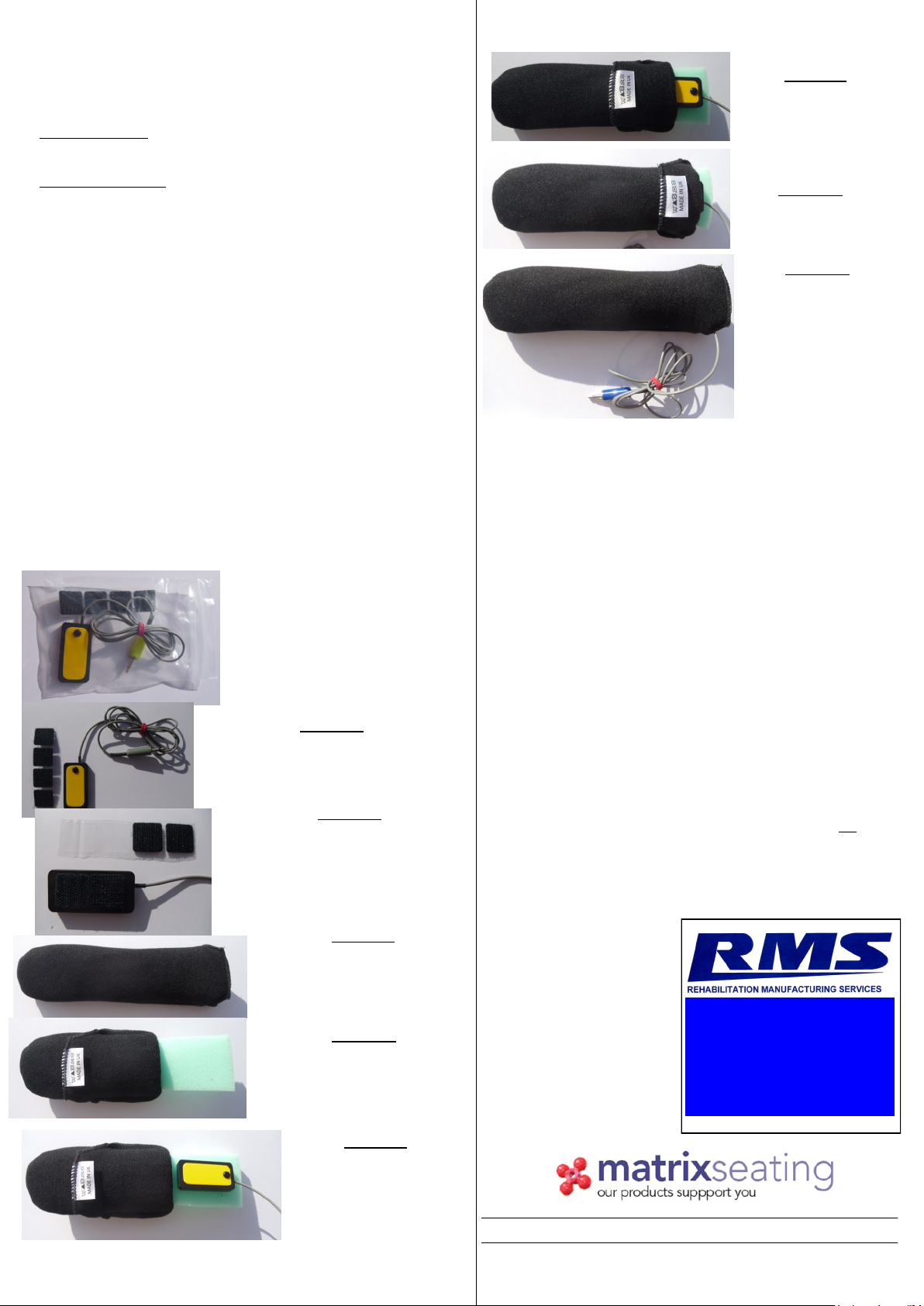
4. HARDWARE
The Heads First Switch is made of three main parts:
The switch body with yellow switch plate
The cable and jack
Velcro self-adhesive hook, square pads
4.1. INFORMATION ABOUT HEADS FIRST FRAME AND EXTENSIONS
The Heads First frame is made of four stainless steel shapes fitted with a
black mounting disc (fitted with 3 countersunk 5mm screws (posidrive num-
ber 2 head)). The shape and hence the comfort and effectiveness is con-
trolled by bending of the frame and its extensions and it is very important
that they should only be adjusted by a professional. For various clients and
situations (ie, powered wheelchair use) it may be necessary to apply Locktite
(type of glue) to the connecting screws or to peen the inner screw thread
(low profile screw) to prevent loosening. Use 12mm wide (1.5mm thick)
blade screwdrivers with care when tightening the low profile screws so as
not to damage the screwdriver slot.
WARNING: This
product has
not been
crash tested
Caution
Caution