MATRIX TECHNOLOGY MPS-3063S User manual

MATRIX TECHNOLOGY INC.
Model:MPS-3063S,MPS-6033S
MPS-3033X,MPS-3063X, MPS-6033X
MPS-3033XP, MPS-3063XP, MPS-6033XP
Version NO.:V1.1
Triple channel programmable DC
power supply
User Manual
MATRIX TECHNOLOGY INC.

MATRIX TECHNOLOGY INC.
User Manual
Chapter 1
Inspection and installation ..................................................................................................................................................... 1
1.1Packin list ......................................................................................................................................................................................... ....... 1
1.2Install power supply .............................................................................................................................................................................. 2
1.3 Adjust the handle ..................................................................................................................................................... ............................3
1.4 Install power cord.................................................................................................................................................................................. 4
Chapter 2
Quick start .................................................................................................................................................................................. 5
2.1 Brief introduction ..................................................................................................................................................................................5
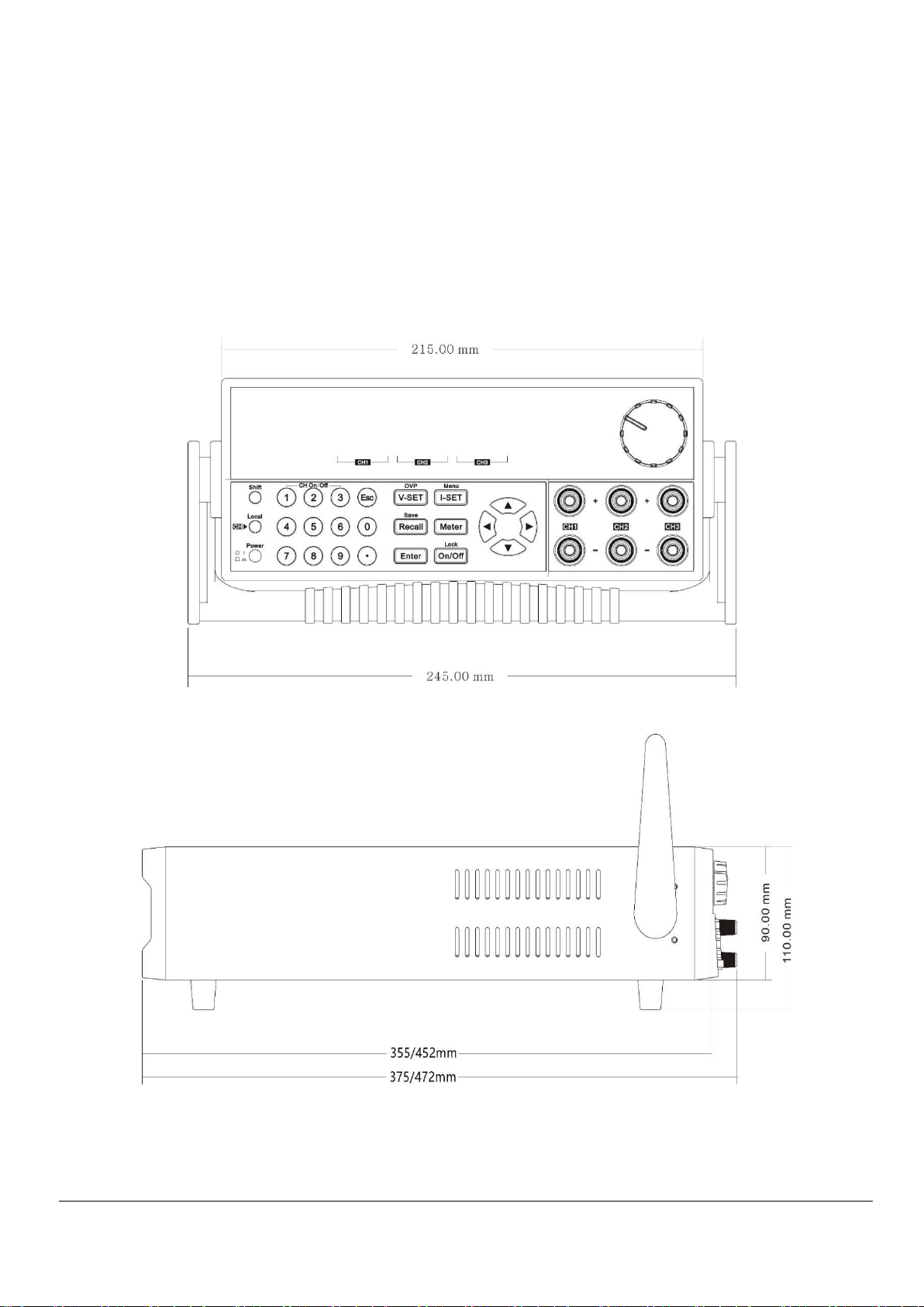
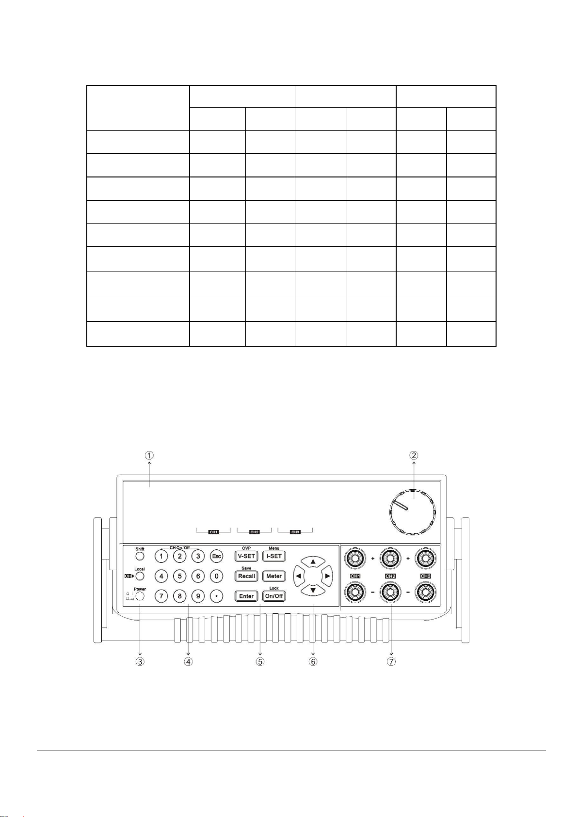
2.2 Front panel introduction..................................................................................................................................................................... 6
2.3 Keyboad introduction ..........................................................................................................................................................................7
2.4 VFD indicator light function description ...................................................................................................................................... 8
2.5 Rear panel introduction.......................................................................................................................................................................8
2.6 Power on self test................................................................................................................................................................................ 9
2.7 Output check......................................................................................................................................................................................... 11
Chapter 3
Fuction and features ............................................................................................................................................................. 10
3.1Front panel operation introduction............................................................................................................................................... 10
3.2 Switch local/remote operations..................................................................................................................................................... 11
3.3 Channel switching operation ......................................................................................................................................................... 12
3.4 OUT ON/OFF output setting ...........................................................................................................................................................13
3.5 Timer operation................................................................................................................................................................................... 15
3.6 Voltage setting operation................................................................................................................................................................ 15
3.7 Current setting operation................................................................................................................................................................. 15
3.8 Data save/recall setting..................................................................................................................................................................... 16
3.9 Over voltage operation..................................................................................................................................................................... 16
3.10 Key board lock function.................................................................................................................................................................. 16
3.11 Over heat protection function...................................................................................................................................................... 16
3.12 Menu function.................................................................................................................................................................................... 17
3.13 Rear panel terminal function......................................................................................................................................................... 23
Chapter 4
Technical specification........................................................................................................................................................... 24
4.1 Main technical specification ........................................................................................................................................................... 24
4.2 Supplementary features.................................................................................................................................................................... 27
Chapter 5
Communication bwtween power supply and computer.................................................................................................... 28
5.1 RS-232 interface................................................................................................................................................................................. 28
5.2 USB interface ...................................................................................................................................................................................... 29
appendix ................................................................................................................................................................................... 29
FAQ ......................................................................................................................................................................................................... 29

Inspection and installation
MATRIX TECHNOLOGY INC.
1
Chapter 1 Inspection and installation
Before installation or operation, please read the safety signs and instructions in
this manual.
1.1 Packing List
Open the package and check the contents of the box before operating the instrument. If
there are any discrepancies, missing or appearance wear, etc., Please contact the seller as
soon as possible.
Accessory name
Quantity
Remark
Three-channel
programmable power
supply
1pc
MPS-3033S, MPS-3063S, MPS-6033S
MPS-3033X, MPS-3063X, MPS-6033X
MPS-3033XP, MPS-3063XP, MPS-6033XP
Power cable
1pc
Users can choose the power cord according to
power socket specifications in different region
Communication line
1pc
RS232/USB communication line
User manual
1pc
Warranty card
1pc
After confirming that the packaging contents are consistent and there is no problem, please
keep the packaging box and related contents properly. The instrument must meet the
packaging requirements when returning the instrument for service.

Inspection and installation
MATRIX TECHNOLOGY INC.
2
1.2 Install the power supply
The instrument needs to be installed in a space with good ventilation and reasonable
size. Please introduce according to the following power supply size Choose a suitable space
for installation.
Three-channel programmable power supply size: 215mm(W)*90mm(H)*355mm(D) / 215mm
(W)*90mm(H)*452mm(D)(MPS-3033XP/MPS-3063XP/MPS-6033XP)
(W: width; H: height; D: depth)
Please refer to the following dimension drawing for details:
Front view
Side view

Inspection and installation
MATRIX TECHNOLOGY INC.
3
1.3 Adjust the power handle
Adjust the position of the power supply, grasp the handle with both hands, pull it to the
left and right sides, and then turn the handle to the desired position.
There are three options for the placement of the power supply:
1.4 Install the power cord
Standard power cord connector fitting, to ensure that the power supply has been
normally powered, and grounded.
Power input requirements
The working voltage of the three-channel power supply has two modes: 110V and 220V.
Please pay attention to the input voltage of the power supply. There is a power cord that
matches your local area in accessories. If you find a mismatch, please contact the
company’s authorized dealer or after-sales service immediately.
Hand position
Table placement
Tips
Do not use excessive force when loading and unloading the power supply handle, and be
careful to pinch your hands.

Inspection and installation
MATRIX TECHNOLOGY INC.
4
AC power input level (can be selected by the switch at the bottom of the power supply)
Option Opt.1: 220VAC ±10% 47Hz-63Hz
Option Opt.2: 110VAC ±10% 47Hz-63Hz
Type of power cord
The power cord model provided by the power supply is shown in the figure below.
Please select the power cord model suitable for the voltage in your area from the power
cord specification table below. If you make a mistake when buying, please contact the
dealer or directly to the manufacturer to exchange.
CN PLUG US/CANADA PLUG EU PLUG UK PLUG

Quick Start
MATRIX TECHNOLOGY INC.
5
Chapter 2 Quick Start
This chapter briefly introduces the front panel, rear panel, keyboard key functions and
VFD display functions of the three-channel power supply to ensure that you can quickly
understand the appearance, structure and key functions of the power supply before
operating the power supply, and help you make better use of this series power supply
2.1 Introduction
Three-channel programmable DC power supply, each output voltage and output
current can be set from 0 to the maximum rated output value. The three-channel power
supply has high resolution, high precision and high stability, and has the functions of
over-voltage and overheat protection. In addition, series and parallel operation modes
are provided to increase the output capacity of voltage or current. With a resolution of
up to 1mV/1mA, it can meet various application requirements. It is an excellent choice
for R&D departments, manufacturers, and teaching and research units. The main special
functions and advantages are as follows:
Optional serial, parallel or synchronous
Three channels can display voltage and current values at the same time
1/2 2U ultra small size
Vacuum fluorescent display (VFD)
Panel function keys LED display
Remote measurement function to compensate for line voltage drop
High resolution and accuracy and high stability
Output can be controlled independently
Over-voltage, overheat protection
Intelligent temperature control fan to reduce noise
Standard USB/RS232 communication interface
Low ripple and noise
Keep memory function when power off
Software monitoring through computer
Can save 40 sets of setting data, quickly store and recall
The knob can be used to adjust the voltage and current
Timing output time (0.1~99999.9 seconds)

Quick Start
MATRIX TECHNOLOGY INC.
6
Three-channel power supply series selection table:
Model
CH1
CH2
CH3
Voltage
Current
Voltage
Current
Voltage
Current
MPS-3033S
30V
3A
30V
3A
6V
3A
MPS-3063S
30V
6A
30V
6A
6V
3A
MPS-6033S
60V
3A
60V
3A
6V
3A
MPS-3033X
30V
3A
30V
3A
6V
3A
MPS-3063X
30V
6A
30V
6A
6V
3A
MPS-6033X
60V
3A
60V
3A
6V
3A
MPS-3033XP
30V
3A
30V
3A
30V
3A
MPS-3063XP
30V
6A
30V
6A
30V
6A
MPS-6033XP
60V
3A
60V
3A
60V
3A
2.2 Introduction to the front panel
Front panel layout.
1. VFD display
2. Knob
3. Power switch, Local key and Shift key

Quick Start
MATRIX TECHNOLOGY INC.
7
4. Number keys and Esc exit key
5. Function keys
6. Move the buttons up, down, left, and right
7. Output terminal
2.3 Introduction to keyboard keys
The key description is as follows:
Key
Name and function
0~9
Number keys (1 to 3 are single output switching key, must
comply with “Shift” Key to use, except LOCK state).
Esc
Return key
Shift
Compound function key
Local
Local key, switch back to local operation / channel switching key.
Power
Switch button.
V-set/OVP
Set the power supply output voltage value / OVP setting.
I-set/Menu
Set the power protection current value / enter the menu setting.
Recall/Save
Retrieve the power setting value from the designated memory
location/store the current power setting value to the designated
memory location.
Meter
Switch between measurement and setting status.
Enter
Enter
On/Off, Lock
Control power output status / keyboard lock
◀ ▶
Move left and right keys to move the cursor or select menu
items in the menu.

Quick Start
MATRIX TECHNOLOGY INC.
8
▲▼
The up and down movement keys are used to increase or
decrease the set value and change the current parameter.
(Shift)+1,
(Shift) +2,
(Shift) +3
In any state (menu setting or METER state), press this key to
immediately turn on/off the corresponding channel output.
2.4 VFD indicator function description
When the power is turned on, if the power appears in any of the signs, the relevant signs
will be displayed at the bottom left of the screen.
The function description of the VFD indicator is as follows:
Character
Function description
C
Constant current operation mode
V
Constant voltage operation mode
�
Keyboard operation is locked
Remote operation mode
↑
Shift key down
▶
Channel selection marker
T
Synchronous operation mode
2.5 Introduction to the rear panel
Power supply, rear panel layout.

Quick Start
MATRIX TECHNOLOGY INC.
9
1. Heat dissipation window
2. RS232 communication interface
3. USB communication interface
4. Remote measurement terminal
5. AC power input socket and fuse
Tips
The 110V/220V power switch is at the bottom of the instrument. Please check the
position of the switch before plugging in the power source to avoid burning the
instrument.
2.6 Power-on self-test
A successful self-inspection process indicates that the power product purchased by the
user meets the factory standards and can be used by the user. Before operating the
power supply, make sure you have understood the safety instructions.
Please make sure that the power supply voltage is consistent with the power supply
voltage before turning on the power, otherwise the power supply will be burned out.
Be sure to connect the main power plug to a power outlet with a protective ground,
and do not use a wiring board without a protective ground. Before operating the
power supply, you should first make sure that the power supply is well grounded.
Please pay attention to the positive and negative signs before wiring the power supply,
otherwise the power supply will be burned out.
WARNING

Quick Start
MATRIX TECHNOLOGY INC.
10
Self-check steps
The power supply normal self-check process is as follows:
1. Connect the power cord correctly, press the power switch to turn on the
power. The power supply performs a self-test.
2. After the power supply self-check is completed, the VFD display shows the
following output voltage and current status as follows.
0.000V 0.000V 0.000V
0.000A 0.000A 0.000A
Error message reference
The following error message may appear when an error occurs during the power supply
self-test:
If the EEPROM is damaged, it will prompt "EEPROM Fail".
If the last saved data in EEPROM is lost, it will prompt "System Lost".
If the transmit channel data, channel response fails, you are prompted to "Model Fail.
If the calibration data reading fails, it will prompt "Cal Lost"
If the factory calibration data is lost, it will prompt "Fact Lost"
If the channel sending data is lost and the channel initialization fails, it will
prompt "Model Lost".
Exception handling
When the power is turned on, the power cannot be started normally, please refer to the
following steps to check and deal with it.
1. Check whether the power cord is connected correctly and confirm that the power
supply is in a powered state.
Good power cord connection => 2
Power connection error => Please reconnect the power cord to check whether the
abnormality is cleared.
2. Whether the power is on. Press the power switch key to switch on the power.
Yes => 3
No => Please press the voltage switch to turn on the power and check whether the
abnormality is cleared.
3. Check whether the fuse of the power supply is burned out.
If the fuse is burned out, replace the fuse. Specific steps are as follows:
1) Unplug the power cord and use a small screwdriver to take out the fuse
box. (See the introduction on the rear panel for the location of the fuse)

Quick Start
MATRIX TECHNOLOGY INC.
11
Fuse specification list:
Model
Fuse specification
( 220V )
Fuse specification
( 110V )
MPS-3033S/MPS-3033X
5A
8A
MPS-6033S/MPS-6033X
6.3A
10A
MPS-3063S/MPS-3063X
6.3A
10A
MPS-3033XP
5A
8A
MPS-3063XP/MPS-6033XP
8A
15A
2) Replace the fuse with same specification, put it in the box, and re-install it.
2.7 Output check
The output check can ensure that the power supply reaches its rated output and can
perform front panel operations correctly.
Output voltage check
Verify the basic voltage function of the power supply without load.
1. Turn on the power supply.
2. Set the power supply current value ( ≥ 0.1A ).
3. Turn on the power output.
Press the ON/OFF function button, and the CV status mark on the VFD display lights
up.
4. Set the power supply voltage.
Set different power supply voltages and wait for the power supply to be in METER
mode, check whether the voltage value displayed on the VFD is close to the set
voltage value, and whether the current value displayed on the VFD is close to 0A.

Quick Start
MATRIX TECHNOLOGY INC.
12
5. Ensure that the power supply voltage can be adjusted from 0V to the maximum
output voltage.
6. Test the voltage of the other two channels in turn.
---- End
Tips
SET mode refers to the setting mode, VFD displays the set value; METER mode refers to
the meter measurement mode, and the VFD displays the actual measurement value. It
can be switched by pressing the button on the panel. When the light
is off, the power supply is in SET mode, otherwise, the power supply is in METER mode.
Output current check
Verify the basic current function of the power supply when the output is short-circuited.
1. Turn on the power supply.
2. Turn off the power output, make sure that the power is OFF, and the OFF status
sign is displayed on the VFD.
3. Connect an insulated wire between the output terminals ( + ) and ( - ) of one of the
channels of the power supply .The wires used should be able to withstand the
maximum output current of the power supply.
4. Set the power supply voltage value to 1V.
5. The power output is turned on.
6. Set the power supply current.
Set different power supply currents and wait for the current value displayed on
the VFD when the power supply is in METER mode.
Whether it is close to the set current value.
7. Ensure that the power supply current can be adjusted from 0A to the rated full output
current of the channel.
8. Turn off the power output and remove the short-circuit wire.
9. Test the current of the other two channels in turn.
---- End
Meter
Meter

Functions and featuresQuick Start
MATRIX TECHNOLOGY INC.
13
Chapter 3 Functions and features
This chapter will describe in detail how to use keys to complete the basic operations of
the three-channel power supply. It will be divided into the following parts:
Front panel operation introduction
Switch local/remote operation
Channel switching operation
OUT ON/OFF output setting
Timer operation
Voltage setting operation
Current setting operation
Data save / read settings
Over-voltage operation
Keypad lock function
Overheat protection function
Menu function
After the end panel functions
3.1 Introduction to front panel operation
Before operating the power supply, please read the following description of the keys on
the front panel.
After the power is turned on, the power supply automatically enters the panel
operation mode. In the panel operation mode, all keys can be used.
The output switch of the power supply can be controlled by pressing the key
on the front panel. When the power is turned on, the status and voltage and current
values of each channel will be displayed on the VFD. "C" represents the constant
current state, and "V" represents the constant voltage state. When the power is in the
OFF state, there is no constant voltage and constant current sign on the VFD.
VFD can display some operating status or error information of the current power
supply. When the power supply is in remote operation mode, the sign will be
displayed. When the power keyboard is locked, the �sign will be displayed, please
refer to the “chapter of VFD mark description”.
If it is in the setting state, turn the knob to change the currently set value. If you are in
the menu state, turn the knob to change the current menu item.
When the / / / / button lights up (displays
yellow-green light), it means it is in the corresponding state. If you press (Shift)+
(Save), the button LED will be on, and it is in a waiting state, and you need to
enter a number for storage.
I-set
Meter
Recall
Recall
On/Off
Recall
V-set
On/Off

Functions and featuresQuick Start
MATRIX TECHNOLOGY INC.
14
The following table lists the states represented by the lights of each key:
Note: 、 、 three lights will not light up at the same time.
3.2 Switch local /remote operation
The power supply provides two operation modes: local operation and remote operation.
Communication commands can be used to switch between the two operating modes.
The power initialization mode defaults to the local operation mode.
Local operation mode: In the local operation mode, all keys can be used. Use the
buttons on the power supply body to perform related operations.
Remote operation mode: The power supply is connected to the PC, and the related
operations of the power supply are performed on the PC. When the power supply is in
the remote operation mode, except for the Meter and Local keys, other keys on the
panel do not work. You can switch to the Local operation mode by pressing the Local
button. When the operating mode is changed, it will not affect the output parameters
of the power supply.
3.3 Channel switching operation
When the voltage setting or current setting is on, press the (Local)
operation key to switch between the three channels.
3.4 OUT ON / OFF output setting
You can use the key to change the state of the power supply. This key is in
the flip state, that is, when the key is pressed when the output is off, the output will be
This light is on, indicating that it is in the voltage setting state.
This light is on, indicating that it is in the current setting state.
This light is on, indicating that it is in the recall state, if it flashes,
it indicates that it is in the storage state.
This light is on, indicating that it is currently in the measurement state,
otherwise it is in the setting state.
This light is on, indicating that at least one channel of the current
power supply is in the on state, otherwise it is in the off state.
V-set
I-set
Recall
I-set
Meter
On/Off
V-set
V-set
I-set
Recall
On/Off

Functions and featuresQuick Start
MATRIX TECHNOLOGY INC.
15
changed to ON; in the same way, when the key is pressed when the output is on, the
output will be changed to the OFF state.
In the case of panel operation, you can use the key to control the output
switch status of all channels, or press the single-channel switch (shift+❶, shift+❷,
shift+❸No. key) to control the output switch status of a channel (number key❶
controls the first channel output status, number key❷controls the output status of the
second channel, number key❸controls the output status of the third channel). In the
case of remote control, you can send SCPI commands (OUTPUT: ON | OFF) to switch the
output state.
The output switch operation does not affect the current set value, and the output switch
series/parallel setting affects the output switch operation.
Tips
The key will simultaneously control three channels. To control the output
status of a single channel, use the single-channel switch key. When the output is turned
on, there will be V or C display in the current display position.
3.5 Timer operation
The output time is set in the menu. After the timing is up, the power supply will
automatically close the timing channel.For timing setting details, please refer to Out
Timer in 3.12 Menu Function Description.
3.6 Voltage setting operation
There are three ways to change the current channel voltage value:
Method 1: Press Local key to switch channels, press key + number
key, press key to confirm, you can directly set the voltage value of the current
channel.
Method 2: Press key, press the“▶ ◀ “ key to adjust the cursor position, turn
the knob to change the number on the selected cursor, and then set the voltage value.
Press to confirm.
Method 3: Press key, press the“ ▶ ◀ ”key to adjust the cursor position, press
the “▲▼”key to change the value of the cursor.Press to confirm
Tips
When the output is off and the light is on, the knob and the up and down keys cannot
adjust the voltage and current parameters; when the knob function is allowed, directly rotate the
knob to set the voltage and current values without pressing the key to confirm.
Press the knob to switch the cursor position.
3.7 Set current
V-set
V-set
Enter
V-set
Enter
Enter
Enter
On/Off
Meter
On/Off

Functions and featuresQuick Start
MATRIX TECHNOLOGY INC.
16
Three Method to change current as below:
Method 1: Press Local key to switch channels, press key+number. Key,
press to confirm, then set the current of the channel directly.
Method 2: Press , then press “▶ ◀ ”(or the knob) to move the cursor position
adjust the current value by rotating the knob, then set the current. Press to
confirm.
Method 3: Press , then press “▶ ◀ “ to move the cursor position and adjust
the current value pressing “▲▼”. Press to confirm.
3.8 Save and recall
The power supply can save some used parameters in 40 groups, divided into 4 areas,
each zone 9 groups (1~9) for users to take out and use conveniently and quickly. These
parameters include voltage upper limit values (MaxVolt), over-voltage value (OVP Set),
voltage setting value, current setting value.
Press Shift + /save followed by a Number key to save the current and voltage setting
to data memory. Press + Number 1 to 9 to recall voltage/current setting value.You can
also use the SCPI command (*SAV、*RCL) to save and recall in 40 groups memory.
Tips
No matter it is saving or recalling, a prompt message of success or failure will be
displayed after pressing Shift +Save/ or , and pressing number key to
save/recall. After pressing Shift + /Save, if the button light is flashing,
It is waiting for inputting number to save. In combination mode, data saving/recalling
is not supported.
3.9 OVP operation
Press Shift + (OVP) to enter into over-voltage setting. After setting OVP
successfully, when the actual voltage exceeds the OVP value, then VFD will display “OVER
VOLT” in corresponding channel. Three channels can set separately.
3.10 Key lock set
Press Shift + (Lock),can lock the front panel, a lock sign will be displayed at
left bottom of VFD.
In key lock mode, all keys are disabled, except ❶,❷,❸(On/Off), key, Meter key,
(Local) key, (Shift)+ Key.
3.11 Over Temperature Protection
I-set
On/Off
Enter
I-set
Enter
I-set
Enter
Recall
V-set
Recall
On/Off
Recall
Recall

Functions and featuresQuick Start
MATRIX TECHNOLOGY INC.
17
If the internal temperature of the power supply exceeds 80℃,the instrument will
protect itself by automatically turning power OFF. When this happens, you will hear a buzzer.
And the display will display the following:
3.12 Menu function
Press Shift + (Menu)to enter into Power Menu. In the menu, right/left arrow
keys and rotary knob used for flow around the menu, change the options used
to identify the current menu commands or into the next layer menu. Press can exit
menu or enter a layer menu.
System
Power Menu
System Menu…
System menu
Out State
Power Out
State Set
Power supply output state Settings
OFF
Always OFF
Keep
Keep the last time state before shutdown
Out Param
Power Out
Param Set
Set up the related parameters
Reset
default
Keep
Restore the last time’s parameters before shutdown
Knob
Knob Function
Set
Knob function setting
Unlock
Open
Lock
Close
Buzzer
Key Beeper Set
Key sound set
OFF
Key sound closed
ON
Key sound open
Communication
Communication
Select
Interface choice set
Port Select
Select communication interface
RS232
RS232
USB
USB
Baud
Select baud rate
4800
9600
19200
38400
Enter
I-set
Over Temperature…
Esc

Functions and featuresQuick Start
MATRIX TECHNOLOGY INC.
18
57600
115200
Memory Group
Select Memory
Group
Memory group set
Grp1
Group 1
Grp2
Group 2
Grp3
Group 3
Grp4
Group 4
Command
Communicatio
Communication version selection
Version Select
Modbus
Modbus command
SCPI
SCPI command
Return Meter
Auto Return
Meter State
Auto return meter state
OFF
Function closed
Wait5Sec
Wait for 5 seconds,back to measurement state
Reset
Reset Menu
Default ?
Back to factory setting
NO
NO
YES
YES
Exit
Config
System menu
Channel Select …
Channel selection
CH1
Config Menu…
Channel 1 menu
Max Volt
Max Voltage Set
Max voltage setting
Max Volt=31.000V
Out Timer
Out Timer Set
Output timer time
setting
This manual suits for next models
7
Table of contents
Other MATRIX TECHNOLOGY Power Supply manuals