MATRIX TECHNOLOGY MPS-3600H Series User manual

User Manual
MPS-3600H Series Programmable DC Power Supplyl I psiv3600
series programmable straight MPS-3600H series programmable DC
power supply
MATRIX TECHNOLOGY INC.
Version No.: 20200506V1

Catalog
CHAPTER 1 PRODUCT INTRODUCTION..........................................................................................................................1
CHAPTER 2 TECHNICAL SPECIFICATION.........................................................................................................................2
2.1 MAIN SPECIFICATION............................................................................................................................................. 2
2.2 ADDITIONAL FEATURES..........................................................................................................................................2
CHAPTER 3 QUICK START..................................................................................................................................................3
3.1 FRONT/REAR PANNEL INTRODUCTION...............................................................................................................3
3.2 PRE-EXAMINE.......................................................................................................................................................... 5
3.3IF THE POWER FAILS TO START..............................................................................................................................5
CHAPTER 4 PANEL OPERATION....................................................................................................................................... 6
4.1 KEYBOARD ARRANGEMENT...................................................................................................................................6
4.2 FRONT PANEL OPERATION INTRODUCTION.......................................................................................................7
4.3 VOLTAGE SETTING OPERATION.............................................................................................................................7
4.4 CURRENT SETTING OPERATION............................................................................................................................ 7
4.5 SAVE/RECALL OPERATION......................................................................................................................................7
4.6 BATTERY CHARGING WARNING FUNCTION........................................................................................................7
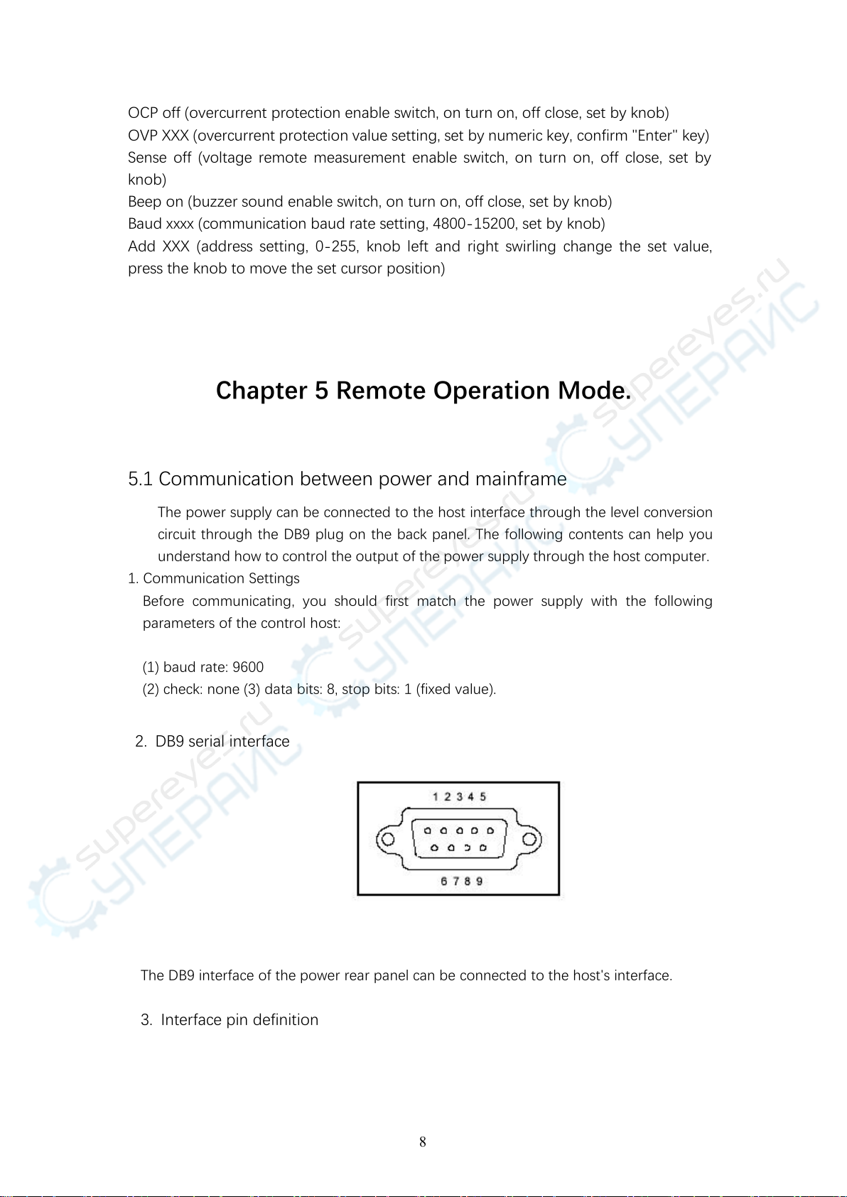
CHAPTER 5 REMOTE OPERATION MODE....................................................................................................................... 8
5.1 COMMUNICATION BETWEEN POWER SUPPLY AND MAIN UNIT..................................................................... 8
CHAPTER 6 SCPI COMMUNICATION COMMAND......................................................................................................... 9
6.1 SCPI COMMAND SUMMARY.............................................................................................................................9
6.2 COMMONLY USED COMMAND DESCRIPTION............................................................................................ 10
6.2.1 BASIC COMMAND......................................................................................................................................... 10
6.2.2 MPS-3600 SPECIFIED COMMAND..............................................................................................................10
6.2.3 MEASURING COMMAND.............................................................................................................................10
6.2.4 SETTING COMMAND....................................................................................................................................11
4.2.7 LIST 功能.........................................................................................................................................................
4.2.8 自动测试功能.....................................................................................................................................................
4.2.8.1 编辑自动测试列表..................................................................................................................................18
4.2.8.2 设置自动测试触发输出方式..................................................................................................................19
4.2.8.3 执行自动测试功能..................................................................................................................................19
4.3 输入控制.....................................................................................................................................................................
4.3.1 短路操作(SHORT)........................................................................................................................................
4.3.2 输入开关操作.....................................................................................................................................................
4.4 电子负载可操作范围.................................................................................................................................................
4.5 保护功能.....................................................................................................................................................................
4.5.1 过电压保护(OV

1
Chapter 1 Product Introduction
The MPS-3600H series is a new generation of high quality programmable DC power supply.
This series of products is equipped with RS232 communication interface. The MPS-3600H
series power supply has both desktop and system characteristics. It can be matched with
other instruments at any time and integrated into a special function testing system to
complete the measurement requirements under different situations, and it can bring great
convenience to users through the panel keyboard editing program. It is a replacement
product of ordinary programmable power supply, and has high cost performance
advantages.
This series of power supply has the following characteristics:
Infinite servo, intelligent fan system
Multi-group data storage
Standard instrument rack design
Support RS232, newsletter
High resolution
Chapter 2 Technical Specification
2.1 Main Technical Specifications
MPS-3600H series power supply specification sheet:
Model
MPS-3603H
36V/3A
MPS-3605H
36/V5A
MPS-6003H
60V/3A
Rated input voltage
AC220V/110V±5%
Rated output voltage
0-36V
60V
Rated output current
0-3A
0-5A
0-3A
Voltage transformation mode
Linear power supply
Load regulation rate
Voltage
<0.02%+5mV
<0.02%+8mV
<0.02%+5mV
Current
<0.02%+5mA
Power regulation rate
Voltage
<0.02%+5mV
<0.02%+8mV
<0.02%+5mV
Current
<0.02%+5mA

2
2.2 Additional features
State memory capacity: 9 sets of operation states
Recommended calibration frequency: 1 / 1 times.
Cooling mode: forced air cooling
Operating environment temperature: 0 to 40℃
Storage environment temperature: -20 to 70℃
Use environment: indoor use design, pollution level 2, maximum humidity 90%.
Chapter 3 Quick Start
This chapter will briefly introduce the appearance and basic functions of MPS-3600H series
power supply, so that you can quickly understand the power supply of MPS-3600H series.
At the same time, we will tell you the basic inspection to ensure the normal operation of
this product after getting the power supply.
3.1 Front and back panel introduction
The front panel of MPS-3600H series power supply is shown below.
Setting resolution
Voltage
1mV
Current
0.1mA
Setting accuracy
(25 ℃± 5 ℃)
Voltage
≤0.05%+8mV
Current
≤0.1%+2mA
≤0.1%+3mA
≤0.1%+2mA
Read back resolution
Voltage
1mV
current
0.1mA
Read back precision
(25℃±5℃)
Voltage
≤0.05%+8mV
current
≤0.1%+2mA
≤0.1%+3mA
≤0.1%+2mA
Temperature
Operating
environment
0 to 40 ℃ ≤ 85 R.H.
Storage
environment
-15 to 70 ℃ ≤ 85 R.H
Size (W*H*D (mm))
214*108*305
214*108*365
Net weight
5.5Kg
5.9Kg
8.2Kg

3
Figure 3.1
(1) the upper part of the front panel is a black LED display and knob.
2. The lower part of the front panel is 0-9 numeric keys and ESC exit keys from left to right,
function keys, up and down movement keys and Enter keys, input and output terminals.
MPS-3600H series rear panel layout, as shown below.
Fig. 3.2 rear panel of MPS-3600H series power supply
① Sense(remote range port)

4
△
!
WARNING: the power supply is equipped with three-cell power cord, so the power supply
should be connected to three-cell socket. Before start up this machine, make sure it is grounded
very well.
② Cooling hole
③ Serial No.
④ Power input switching.
⑤ RS232 communication interface
⑥ Power input socket
3.2 Pre-check
Please check the power supply according to the following steps to ensure that the power
supply can be used normally.
1. inspection
Please check whether you receive the following attachments when you receive the power
supply. If there is any missing, please contact your nearest dealer.
A power cord (in line with the voltage standards used in the region).
An operation manual (standard)
A certificate of qualification (standard)
2. connect the power cord and turn on the power supply.
After power on, the power supply is self tested first, then enters standby mode.
3.3 if the power fails to start
1. check whether the power cord is connected properly.
Use the following methods to solve the problems you may encounter when you turn
on the power supply.
Model
fuse value
230V
115V
MPS-3603H
3.15A
5A
MPS-3605H
5A
6A
MPS-6003H
10A
12A

5
2. ways to replace fuse
Use screwdriver to open the small plastic cover below the power input socket of the power
supply, you can see the fuse, please use the fuse with the same specification.
Chapter 4 Panel Operation.
This chapter will detail the operation of the power front panel, which is divided into the
following parts:
◆Keyboard arrangement
◆ Front panel operation introduction
◆ Voltage setting operation
◆ Current setting operation
◆ Storage operation
◆ Menu operation
◆ Output turn on/off operation
4.1 Keyboard Arrangement
Keynote description
Key position
Key function description
0-9:
Number key
Menu (number key "1"):
Menu settings (function when pressing with shift key, setting OVP/OCP,
remote measurement, etc.)
Local (numeber key "7"):
Local operation (and shift combination is effective when pressed, disconnect
from computer)
Battery (numeric key
Battery charging early warning function, voltage and current upper and

6
"8"):
lower limit set (and shift combination is effective when pressed).
CRL (function word key
"Save"):
Not open
I-Set
Set the maximum output current of the power supply.
V-Set
Setting the output voltage of the power supply
Save
Store the relevant parameters of the power supply to the specified storage
location.
Recall
Set the power related settings parameters from the specified storage
location.
Shift
Composite key, combined with multi function key.
On/off
Control power output state
▲
Up conversion key (select menu item in menu operation, increase output
voltage at work interface)
▼
Down button (menu item is selected in menu operation, and output voltage
can be reduced at work interface).
Enter
Acknowledgement key
knob
Used to change the supply voltage and current setting.
4.2 Front Panel Operation Introduction
Before using this power supply, please understand the following basic introduction to
the key operation of front panel.
The C machine controls switching. When the operation mode changes, the output
parameters of the power supply will not be affected.
4.3 Voltage Setting Operation
The voltage setting range is between 0V and the maximum voltage setting. You can use
the following three ways to set the output voltage value through the front panel.
Method 1: after power supply is switched on, press voltage and key directly to change
the voltage setting value.
Method two: press the V-Set key + 0 to 9 numeric keys, and press the Enter button to
set the voltage value.
Method three: change the setting value of the voltage through the rotation of the
knob. (the knob is pressed to the inside, the screen flickers can rotate and set the
voltage and current. By pressing the knob, it can move the cursor position and press
the "Enter" button to confirm and exit the setting mode. If the "Iset or Vset" button is
pressed down, the knob will be locked.
4.4 Current Setting Operation
The setting range of constant current is between 0A and full rated output current.

7
Method 1: operation steps
①. Press the I-Set key.
②, press the 0 to 9 numeric keys to input the current value you need.
③. Press Enter key to confirm.
Method 2: change the setting value of the voltage through the rotation of the knob.
(the knob is pressed to the inside, the screen flickers can rotate and set the voltage and
current. By pressing the knob, it can move the cursor position and press the "Enter"
button to confirm and exit the setting mode. If the "Iset or Vset" button is pressed
down, the knob will be locked.
4.5 Access Operation
The power supply can store some commonly used parameters in 9 sets of non-volatile
memory for users to quickly tune out. You can use the front panel Save and Recall keys
to realize (0~9) access operation of group storage area.
Storage contents include: 1. voltage setting value 2. current setting value.
You can use the Save key + 0 to 9 numeric keys and press the Enter key to store the
power parameters in the specified storage area.
You can use the Recall key + 0 to 9 numeric keys and press the Enter key to remove
the parameters from the specified storage area.
4.6 Battery charging warning function, voltage / current upper and
lower limit setting
Press shift and press the number key "8" to enter the battery charging warning
function. The upper and lower limits of the current are set, and the screen is shown in
sequence as follows:
U_lx.xxxx (voltage lower limit)
U_hx.xxxx (upper voltage limit)
C_l x.xxxx (lower current limit)
C_h x.xxxx (current limit)
Change the set value with the digital key, confirm with the "Enter" key, and alarm when
it is not in range.
4.7 Menu setup
Press shift and the numeric key "1" to enter the menu setting function. Through the up and
down key or the "Enter" key, the menu is displayed.
OUP off (overvoltage protection enable switch, on turn on, off close, set by knob)
OUP XXX (overvoltage protection value is set, set by numeric key, and "Enter" key is
confirmed).

8
OCP off (overcurrent protection enable switch, on turn on, off close, set by knob)
OVP XXX (overcurrent protection value setting, set by numeric key, confirm "Enter" key)
Sense off (voltage remote measurement enable switch, on turn on, off close, set by
knob)
Beep on (buzzer sound enable switch, on turn on, off close, set by knob)
Baud xxxx (communication baud rate setting, 4800-15200, set by knob)
Add XXX (address setting, 0-255, knob left and right swirling change the set value,
press the knob to move the set cursor position)
Chapter 5 Remote Operation Mode.
5.1 Communication between power and mainframe
The power supply can be connected to the host interface through the level conversion
circuit through the DB9 plug on the back panel. The following contents can help you
understand how to control the output of the power supply through the host computer.
1. Communication Settings
Before communicating, you should first match the power supply with the following
parameters of the control host:
(1) baud rate: 9600
(2) check: none (3) data bits: 8, stop bits: 1 (fixed value).
The DB9 interface of the power rear panel can be connected to the host's interface.
3. Interface pin definition
2. DB9 serial interface

9
1
NC
2
RXD (receive)
3
TXD (send)
4
NC
5
GND (land)
6
NC
7
NC
8
NC
9
NC
Chapter 6 SCPI communication protocol.
6.1 SCPI command overview
MPS-3600H series programmable DC power supply supports SCPI communication
protocol.Scpi is a standard command for programmable instruments. It defines a set of
command rules for communication. Commands for iv3600 series power are divided
into two main categories: basic command (ieee-488.2 common command set) and
MPS-3600H series specified command set.
The SCPI commands are arranged in a hierarchy of command trees. Each command
contains many strings (mnemonic symbols), and the layers are separated by colon (:).
The command at the top of the command tree is called "root command" or "root". To
access the next command, a path must be specified. The structure of the command
tree is as follows:
In the graph, AA represents the root path; BB, CC, DD represent the direct subpath.Ee
under the root path, FF, GG represents the subpath. Hh under the subpath BB, and JJ is the
subpath under the subpath DD.
Command description:
1) [:]aa:cc indicates that the root path is AA, and cc. is accessed under AA.
2) [[]aa:bb:ff] indicates that the root path is AA, and the ff. under the subpath BB under
the AA root path is accessed.
3) [[]aa:dd:hh] indicates that the root path is AA, and the hh. under the subpath DD

10
under the AA root path is accessed.
This command can also send multiple commands at the same time, separating the
commands with semicolons (()).
For example: []aa:bb:ee; FF; GG represents EE, FF, gg. under BB.
[:]aa:bb:ff:: aa:dd:hh represents hh. under FF and DD under BB access.
There are two types of mnemonic characters in SCPI language, that is, keywords, long
format and short format. Short format is actually abbreviation for long format.
The short format mnemonic is composed of the first 4 characters of the long format
mnemonic. If the length of the long format mnemonic character is less than or equal to 4,
the length mnemonic is the same.
* if the length of the long mnemonic is greater than 4 and the fourth character is vowel, the
short mnemonic will discard fourth characters and turn the vowel into 3 characters.
For example, the short mnemonic of ERR or is ERR, not ERRO..
Some commands need parameters, such as set value command. At this point, a space
between the command and its first parameter is required (ASCII code is 32).
For example, set the voltage value command [:]volt 12
There is a space between the parameters 12 and the volt command (ASCII code is 32).
The command set of SCPI is not sensitive to case, that is, the command is not case
sensitive, and each command has a terminator for the EOI: instruction to end <LF> (which
means ASCII code character 'n' ', that is, ASCII code line break, decimal 10, sixteen binary
0A).
Note: all the following instructions need to be added to the end of the instruction. The
square brackets [<lf>.] below indicate that the string can be written in the command or not.
6.2 MPS-3600H Power command set
6.2.1 basic command (ieee-488.2 common command set)
This command includes general functions defined in the ieee488.2 standard, which are
usually applicable to measuring instruments that support the ieee488.2 standard. This
command is started with asterisk (*) without hierarchical structure.
Command *idn?
This command can read the relevant information of the power supply, such as
manufacturer, product type, product serial number, firmware version number.
6.2.2 System command
The commands in this section are all commands under []SYSTem root path. The commands
given are all in a short mnemonic format.
Order []SYSTem:ERRor:?
This command is used to read the error code and error message of the power supply.
Return command: error code, error message
Example: send the command to [:]
SYST:ERR?
<LF>

11
The power returned commands are "0,'No Error'", or "50,'Error Para Count'", or
"70,'Invalid Command'" and so on.
Order [:]SYSTem:REM
The command is used to set up the power supply for remote control mode, that is, PC
control mode.
Return command: None
Example: send the command to [:]
SYST:REM
<LF>
After the transmission is successful, the front panel of the power supply is set to the remote
control mode. At this time, the key on the front panel is invalid. Only by pressing the Shift+
number 7 key, or sending the command []SYST:LOC: can the power supply be switched to
the front panel of the power supply.
Order [:]SYSTem:LOC
The command is used to set the power supply to the panel control mode.
Return command: None
Example: if the power is in remote control mode (PC) at this time, send the command
[:]
SYST:LOC
<LF>
After the transmission is successful, the front panel of the power supply has been set to the
front panel control mode.
6.2.3 Measurement command
The commands in this section are all commands under [MEASure root path. The commands
given are all in a short mnemonic format.
Order []MEASure:VOLTage:?
The command is used to read the output voltage value of the power supply.
Return command: numeric value
Return parameter unit: v
Example: the order sent is: [:]
MEAS:VOLT?
<LF>
At this time, the power return command is: 12.560, which means the current value of
the power supply is 12.560v.
Order []MEASure:CURRent:?
The command is used to read the output current value of the power supply.
Return command: numeric value
Return parameter unit: a
Example: the order sent is: [:]
MEAS:CURR?
<LF>

12
At this point, the power return command is 1.245, which means the current supply
current value is 1.245a.
Order []MEASure:VC:?
The command is used to read two measurements at a time: output voltage and
output current.
Returns the command: numeric list, separated by commas in the middle.
Return parameters: V and a
Example: the order sent is: [:]
MEAS:VCM?
<LF>
At this time, the power return command is 10.0000,0.00000, that is, the output voltage
value of the current power is 10.0000v, and the output current value is 0.00000a.
6.2.4 Setup command
Order []OUTPut <bool>
1, the command is used to set the output of the power to turn on or not.
Return command: None
Parameters: type bool parameters, 0 - OFF, 1 - ON
Example: the sending instruction is: [:]
OUTP 1
<LF>
After the transmission is successful, the output of the power is set to open.
Order []VOLTage <Value>
1. The command is used to set the voltage value of the power supply.
Setting: v
Return command: None
Example:
1) send the command to [:]
VOLT 30.000
<LF>
That means the current voltage of the set power is 30V..
Example:
1) If you want to inquire the voltage setting value of the power supply, that is, the
order sent is: [:]
VOLT?
<LF>
Order []CURRent <Value>
1. The command is used to set the current value of the power supply.
Parameter: numerical |max|min
Setting: a
Return command: None

13
Example:
1) send the command to [:]
CURR 3.000
<LF>
That means the current value of the power supply is 3a..
2. Related commands: inquire about the current setting value of the power supply.
[:]CURR? MAX|MIN
Return command parameter: numeric value
Example:
2) If you want to inquire about the current setting value of the power supply, that is,
the order sent is: [:]
CURR?
<LF>
If the power return command is 1, the current setting value of the power supply is
1.0000a..
Security
Do not install spare parts on the instrument or carry out any unauthorized
modification. Please send the instrument to our maintenance department for maintenance
so as to ensure its safe use.
Please refer to the specific warnings or precautions in this manual to avoid personal injury
or instrument damage.
SAFETY SIGN
Warning
It reminds users, be careful about the operation steps which can heart people.
Attention
It reminds users to be careful about the operation step which may break equipment or lose
data permanently
Grounding point
High Voltage(non-professionals are not allow to turn on the machine
Read warnings and attentions carefully(wear gloves when the voltage is high, do not
place the machine at dangerous situation

14
Certification and quality assurance
The MPS-3600H series of programmable DC power reaches all the technical specifications
specified in the manual.
QA
The company guarantees the quality and quality of this product for one year from the date
of shipment.
Maintenance service
If the product is to be repaired, please send the product back to the designated
maintenance unit of our company. The customer must bear the one-way freight to send
the repair product to our maintenance department. The company will be responsible for
paying the return freight. If the product is returned to factory maintenance from other
countries, all the freight, tariff and its duties must be borne by the customer.
Quality assurance restriction
The above warranty does not apply to any damage caused by the following circumstances:
Customers are incorrect or improper in repairing products.
Customers use other software or interfaces.
Unauthorized modification or misuse;
Operate the product outside the designated environment, or configure and maintain it at a
non designated maintenance point.
The damage caused by the circuit installed by the customer.
Announcement
The contents of this manual are subject to change without prior notice, and the power of
interpretation belongs to the company.
This manual suits for next models
3
Table of contents
Other MATRIX TECHNOLOGY Power Supply manuals
Popular Power Supply manuals by other brands

Life technologies
Life technologies novex PowerEase 500 user guide

Altronix
Altronix SMPWP Series installation guide

nextys
nextys NCU120-12 instruction manual

Thermal Dynamics
Thermal Dynamics CE PAK Master 75XL operating manual

Elenco Electronics
Elenco Electronics XP-650 instruction manual

I-Tech
I-Tech IT6700 Series user manual

Circuit Specialists
Circuit Specialists CSI3303S user manual

Peak
Peak PKC0AN owner's manual

Argantix
Argantix KDC 30-167 user manual

Tektronix
Tektronix KEITHLEY 2200 Series Programming reference

CARLO GAVAZZI
CARLO GAVAZZI SPDE 75 Series Installation and operation manual

Sun Microsystems
Sun Microsystems Sun Storage J4200 Replacement guide