Matrix U7XE-03 User manual

U7XE-03 BIKE
SERVICE MANUAL

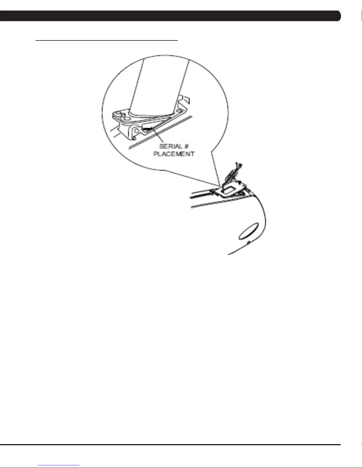
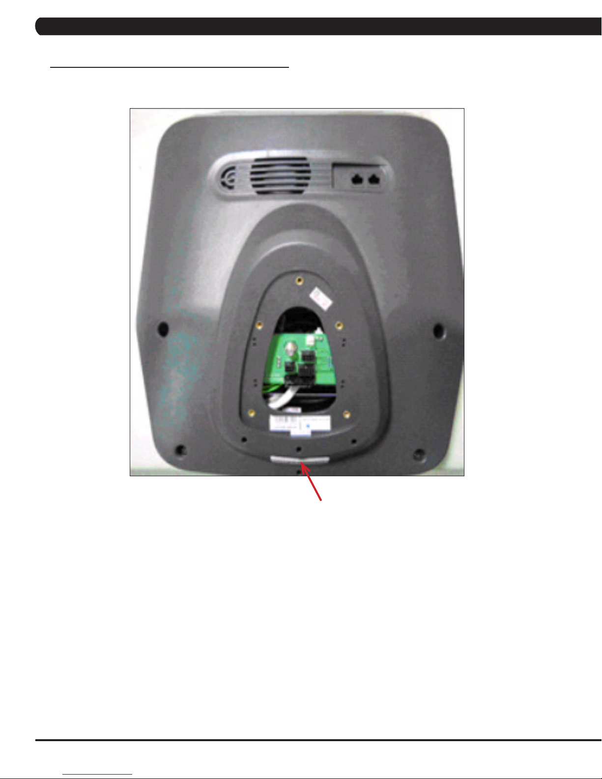
CHAPTER 1: SERIAL NUMBER LOCATION ................................................................... 1
CHAPTER 2: IMPORTANT SAFETY INSTRUCTIONS
2.1 Read and Save These Instructions ........................................................................... 3
2.2 Electrical Requirements ............................................................................................ 4
CHAPTER 3: PREVENTATIVE MAINTENANCE
3.1 Recommended Cleaning Tips ................................................................................... 5
3.2 Check for Damaged Parts ......................................................................................... 5
3.3 Care and Maintenance Instructions .......................................................................... 6
3.4 Touch Screen Care and Cleaning.............................................................................. 7
CHAPTER 4: CONSOLE OVERLAY AND WORKOUT DESCRIPTION
4.1 Console Description .................................................................................................. 8
4.2 Workout Setup Steps ................................................................................................. 9
CHAPTER 5: MANAGER MODE
5.1 Manager Mode Overview .......................................................................................... 10
5.2 Manager Mode - About Tab........................................................................................ 11
5.3 Manager Mode - Time Tab......................................................................................... 12
5.4 Manager Mode - Defaults Tab.................................................................................... 12
5.5 Manager Mode - TV Tab ............................................................................................ 13
5.6 Manager Mode - Language Tab................................................................................. 14
5.7 Manager Mode - Other Tab........................................................................................ 15
CHAPTER 6: ENGINEERING MODE
6.1 Engineering Mode Overview...................................................................................... 16
6.2 Engineering Mode - Calibration Tab........................................................................... 16
6.3 Engineering Mode - Statistics Tab ............................................................................. 17
6.4 Engineering Mode - Errors Tab .................................................................................. 17
6.5 Engineering Mode - Clubs Tab................................................................................... 18
6.6 Engineering Mode - Club ID Tab................................................................................ 18
CHAPTER 7: SERVICE MODE
7.1 Service Mode Overview ............................................................................................. 19
7.2 Service Mode - Setup Tab.......................................................................................... 20
7.3 Service Mode - Test Tab ............................................................................................ 21
7.4 Service Mode - Log Tab ............................................................................................. 22
7.5 Service Mode - Date & Time Tab............................................................................... 22
CHAPTER 8: TROUBLESHOOTING
8.1 Electrical Diagram ..................................................................................................... 23
8.2 Error Codes on the Console ...................................................................................... 24
8.3 LCB LED Instructions................................................................................................. 25
8.4 Troubleshooting - Display Issues ............................................................................... 26
8.5 Troubleshooting - Error Ox04A0 ................................................................................ 27
8.6 Troubleshooting - Touch Pad Issues.......................................................................... 28
8.7 Troubleshooting - Resistance Issues ......................................................................... 29
8.8 Troubleshooting - Pedal Slipping ............................................................................... 30
8.9 Troubleshooting - Noise Issues.................................................................................. 30
8.10 Troubleshooting - Heart Rate Issues ......................................................................... 31
8.11 TV Troubleshooting Overview .................................................................................... 32
8.12 TV Troubleshooting - Picture Fuzzy or Unclear ......................................................... 33
8.13 TV Troubleshooting - TV Will Not Turn On ................................................................ 34
8.14 TV Troubleshooting - Entertainment Keypad Issues ................................................. 35
TABLE OF CONTENTS

III
CHAPTER 9: PART REPLACEMENT GUIDE
9.1 Console Replacement................................................................................................ 36
9.2 Heart Rate Handlebar Replacement ......................................................................... 37
9.3 Heart Rate Grip Replacement ................................................................................... 38
9.4 Cup Holder Replacement........................................................................................... 39
9.5 Console Keypad / Overlay Replacement................................................................... 40
9.6 Console Mast Removal.............................................................................................. 42
9.7 Seat Pad Replacement .............................................................................................. 43
9.8 Seat Post Replacement ............................................................................................. 44
9.9 Seat Post Insert Replacement .................................................................................. 45
9.10 Pedal Replacement.................................................................................................... 46
9.11 Shrouds Removal....................................................................................................... 47
9.12 Lower Control Board Replacement ........................................................................... 48
9.13 Battery Replacement.................................................................................................. 49
9.14 Drive Belt Replacement ............................................................................................. 50
9.15 Generator Belt Replacement...................................................................................... 51
9.16 Generator Replacement............................................................................................. 52
9.17 Pulley Axle Set Replacement.......................................................................................... 53
9.18 Crank Axle Set Replacement.......................................................................................... 55
9.19 Rear Stabilizer Replacement.......................................................................................... 56
9.20 Front Stabilizer Replacement ......................................................................................... 57
9.21 Testing the Bike............................................................................................................... 58
CHAPTER 10: BIKE SPECIFICATIONS AND ASSEMBLY GUIDE
10.1 U7xe-03 Bike Specifications ...................................................................................... 59
10.2 Fasteners and Assembly Tools .................................................................................. 60
10.3 Assembly Instructions ............................................................................................... 61
10.4 Adjusting the Pedal Straps and Seat ......................................................................... 65
10.5 Leveling the Bike........................................................................................................ 66
10.6 TV Programming Instructions..................................................................................... 67
CHAPTER 11: SOFTWARE UPGRADE GUIDE
11.1 Software Upgrade Instructions................................................................................... 70
TABLE OF CONTENTS

1
1.1 SERIAL NUMBER LOCATION
A serial number plate is located below the bottom of the console mast beneath a rubber boot. There is also a serial number tag on the middle
of the main frame pointed towards the floor.
CHAPTER 1: SERIAL NUMBER LOCATION

2
UNIVERSAL CONSOLE SERIAL NUMBER LOCATION
1.1 SERIAL NUMBER LOCATION
CONSOLE SERIAL NUMBER LOCATION
CHAPTER 1: SERIAL NUMBER LOCATION

3
CAUTION! If you experience chest pains, nausea, dizziness,
or shortness of breath, stop exercising immediately and con-
sult your physician before continuing.
CAUTION! Any changes or modifications to this equipment
could void the product warranty.
2.1 READ AND SAVE THESE INSTRUCTIONS
To ensure your safety and protect the equipment, read all
instructions before operating the MATRIX U7xe-03 Bike.
To ensure proper use of the Matrix U7xe-03 Bike, make sure
that all users read this manual. Remind the users that before
undertaking any fitness program, they should obtain complete
physical examinations from their physicians. If, at any time while
exercising, the user experiences dizziness, pain, or shortness of
breath, nausea or feels faint, he or she must stop immediately.
* This bike is only to be used for its intended purpose described
in this manual. Do not use attachments that have not been recom-
mended by Matrix.
* Never drop or insert objects into any opening. Keep hands away
from moving parts. If the item cannot be reached, contact a Matrix
authorized dealer for assistance.
* Never operate the unit if it is damaged, not working properly, when
it has been dropped, or has been dropped in water.
* Keep hands and feet clear at all times from moving parts to avoid
injury.
* Do not use this product outdoors, near swimming pools or in areas
of high humidity.
* Do not operate where aerosol (spray) products are being used or
when oxygen is being administered.
* Do not use this product in bare feet. Do not wear shoes with heels,
leather soles, cleats, or spikes while exercising.
* Do not remove the side covers. Service should only be done by an
authorized service technician.
* Close supervision is necessary when used near children, invalids,
or disabled people.
* When the bike is in use, young children and pets should be kept at
least 3 meters / 10 feet away.
* Assemble and operate the bike on a solid, level surface.
* Never face backward while using the Matrix U7xe-03 Bike.
* Use the stationary handlebars when mounting or dismounting the
bike.
* Do not wear clothing that might catch on any moving parts of this
bike.
CHAPTER 2: IMPORTANT SAFETY INSTRUCTIONS

4
2.2 ELECTRICAL REQUIREMENTS
CHAPTER 2: IMPORTANT SAFETY INFORMATION
CONSOLE POWER
The Matrix Upright Bike console has a battery that makes it self powered. This means that even if the unit is not plugged in, the console may
still have power for up to 12 hours. If the console power needs to be reset or turned off, press and hold the CHANNEL UP and CHANNEL
DOWN keys for 3-5 seconds until the console turns off. The console power will also need to be reset if settings are changed in Manager,
Engineering, or Service Modes.
GROUNDING INSTRUCTIONS:
The Matrix U7xe-03 Upright Bike must be grounded. If it should malfunction or break down, grounding provides a path of least resistance for
electric current to reduce the risk of electric shock. The Bike is equipped with a cord having an equipment grounding conductor and a grounding
plug. The plug must be plugged into an appropriate outlet that is properly installed and grounded in accordance with all local codes and
ordinances. If the user does not follow these grounding instructions, the user could void the Matrix limited warranty.
DANGER: Improper connection of the equipment grounding conductor can result in the risk of electric shock. Check with a qualified electrician
if the user is in doubt as to whether the product is properly grounded. Do not modify the plug provided with the product if it will not fit the outlet,
have a proper outlet installed by an electrician.
The Matrix 7xe Series Upright Bike is designed to be self powered. NOTE: If an add on TV (using a bracket) or Virtual Active is added to the
unit, it must be plugged in, or the TV and Virtual Active will not operate correctly. If the Bike will be plugged in, follow the requirements below.
MATRIX DEDICATED CIRCUIT/ELECTRICAL REQUIREMENT INFO
All Matrix Bikes require the use of a 15 amp or 20 amp “dedicated circuit,” with a non-looped (isolated) neutral/ground, for the power requirement.
Quite simply this means that each outlet you plug Bikes into should not have anything else running on that same circuit besides other Bikes (up to
3 per 15 amp circuit and 4 per 20 amp circuit). The easiest way to verify this is to locate the main circuit breaker box, and turn off the breaker(s)
one at a time. Once a breaker has been turned off, the only thing that should not have power to it are the Bikes in question. No lamps, vending
machines, fans, sound systems, or any other item should lose power when you perform this test.
Non-looped (isolated) neutral/grounding means that each circuit must have an individual neutral/ground connection coming from it, and terminating
at an approved earth ground. You cannot “jumper” a single neutral/ground from one circuit to the next.
In addition to the dedicated circuit requirement, the proper gauge wire must be used from the circuit breaker box, to each outlet that will have the
maximum number of units running off of it. If the distance from the circuit breaker box, to each outlet, is 100 ft or less, then 12 gauge wire may be
used. For any distance greater than 100 ft from the circuit breaker box to the outlet, 10 gauge wire must be used.
For your safety and Bike performance, the ground on this circuit must be non-looped. Please refer to NEC article 210-21 and 210-23. Your Bike is
provided with a power cord with a plug listed below and requires the listed outlet. Any alterations of this power cord could void all warranties for
this product. Multiple Bikes can be powered on one dedicated circuit. (3 units per 15 Amp and 4 units per 20 Amp dedicated circuit.)

5
Preventative maintenance and daily cleaning will prolong the life and look
of your MATRIX U7xe-03 Bike
Please read and follow these tips.
* Position the equipment away from direct sunlight. The intense UV
light can cause discoloration on plastics.
* Locate your equipment in an area with cool temperatures and low
humidity.
* Clean with a soft 100% cotton cloth.
* Clean with soap and water or other non-ammonia based all purpose
cleaners.
* Wipe seats, pedals, console, heart rate grips, and the handlebar clean
after each use.
* Do not pour liquids directly onto your equipment. This can cause dam-
age to the equipment and in some cases electrocution.
* Check pedal straps weekly for wear.
* Adjust leveling feet when equipment wobbles or rocks.
* Maintain a clean area around the equipment, free from dust and dirt.
DO NOT use any equipment that is damaged or has worn or
broken parts. Use only replacement parts supplied by Matrix
Fitness Systems.
MAINTAIN LABELS AND NAMEPLATES. Do not remove labels
for any reason. They contain important information. If unreadable
or missing, contact Matrix Fitness Systems for a replacement at
866-693-4863 or www.matrixfitness.com.
MAINTAIN ALL EQUIPMENT. Preventative maintenance is the
key to smoothly operating equipment. Equipment needs to be
inspected at regular intervals. Defective components must be
kept out of use until they are repaired. Ensure that any person(s)
making adjustments or performing maintenance or repair of any
kind is qualified to do so. Matrix Fitness Systems will provide
service and maintenance training at our corporate facility upon
request or in the field if proper arrangements are made.
3.2 CHECK FOR DAMAGED PARTS
3.1 RECOMMENDED CLEANING TIPS
CHAPTER 3: PREVENTATIVE MAINTENANCE

6
3.3 CARE AND MAINTENANCE INSTRUCTIONS
CHAPTER 3: PREVENTATIVE MAINTENANCE
In order to maximize life span, and minimize down time, all MATRIX equipment requires regular cleaning, and maintenance items performed on
a scheduled basis. This section contains detailed instructions on how to perform these items and the frequency of which they should be done.
Some basic tools and supplies will be necessary to perform these tasks which include (but may not be limited to):
* Metric Allen wrenches
* #2 Phillips head screwdriver
* Adjustable wrench
* Torque wrench (capability to read foot lbs and inch lbs)
* Lint free cleaning cloths
* Teflon based spray lubricant such as "Super Lube" or other Matrix approved products.
* Mild water soluble detergent such as "Simple Green" or other Matrix approved products
* Vacuum cleaner with an extendable hose and crevasse tool attachment.
You may periodically see addendums to this document, as the Matrix Technical Support Team identifies items that require specific attention, the
latest version will always be available on the Matrix web site at www.matrixfitness.com.
DAILY MAINTENANCE ITEMS
1) Look and listen for loose fasteners, unusual noises, and any other indications that the equipment may be in need of service.
2) Clean the bike before and after each use, including:
a. Use a damp, soft cloth with water or mild liquid detergent to clean all exposed surfaces. DO NOT use ammonia, chlorine, or any acid
based cleaners. NOTE: Spray cleaner onto a cloth before using, never spray cleaner directly onto the equipment.
b. Keep the console display free of fingerprints and salt build up caused by sweat.
3) Attempt to wobble the unit from side to side and front to back. Level if needed (see Section 10.5).
WEEKLY MAINTENANCE ITEMS
1) Frequently vacuum the floor beneath the unit to prevent the accumulation of dust and dirt which can affect the smooth operation of the unit.
2) Check the pedal straps for damage.
3) Clean the grooves on the foot pedals.
MONTHLY MAINTENANCE ITEMS
1) Inspect the console, seat, pedals, and shrouds for damage.
2) Tighten the pedals onto their respective cranks using a 15 mm wrench.
3) Adjust the leveling feet if equipment rocks or wobbles.
4) Clean the seat post track with a 100% cotton cloth.
YEARLY MAINTENANCE ITEMS
1) Remove the front shrouds and check the belt for damage, alignment, and proper tension.

7
3.4 TOUCH SCREEN CARE & CLEANING
TOUCH SCREEN CARE AND CLEANING
* The touch screen requires very little maintenance. We recommend that you periodically clean the touch screen surface with a dry soft cloth.
If necessary, we recommend the usage of Alcohol or Isopropyl Alcohol for difficult stains or sanitary purposes.
* It is very important to avoid using any other chemical on the touch screen.
* Always dampen the cloth and clean the screen. Do not spray the cleaning agent on the screen itself, the drips can seep into the display or
stain the bezel.
* After cleaning, make sure the surface is dry. There should not be any left over solvent to seep into the display.
* It is very important to handle the touch screen with care. Do not use excessive force when cleaning.
* Do not use any sharp materials to clean the touch screen surfaces.
* Do not use high pressure air, water, or steam to clean the touch screen surface.
CHAPTER 3: PREVENTATIVE MAINTENANCE

8
4.1 CONSOLE DESCRIPTION
The U7xe-03 has a fully integrated touch screen display. All information required for workouts is explained on screen. Exploration of the interface
is highly encouraged. The information explaining how to program for various workouts will give an explanation about the contents of each screen.
GO: One touch Start.
STOP: Ends workout and shows workout summary data.
U7XE-03 ENTERTAINMENT ZONE
iPOD®: Will take the user directly to the iPod screen to allow for iPod control and playlist selection.
VOLUME UP / DOWN: Adjusts the volume output through the headphone jack of the integrated console TV or iPod output.
NUMBER KEYPAD: Allows for easy TV channel selections.
CHANNEL UP / DOWN: Allows for channel selection.
DISPLAY MODE: Allows user to cycle through console display options, iPod, TV, or profile display.
LAST CHANNEL: Allows the user to cycle between the current channel and the previous channel viewed.
CHAPTER 4: CONSOLE OVERLAY AND WORKOUT DESCRIPTION

9
4.2 WORKOUT SETUP STEPS
To set up a workout, press the touch screen over the program you would like to use and then follow the prompts to begin your workout.
GO - Press to immediately begin a workout. Workout, resistance level, and time will automatically go to default settings. Pressing GO will not
prompt user for age, weight, or level settings.
MANUAL - Manual allows the user to input more information while defining their own workout. Calorie expenditure will be more accurate when
inputting information in Manual than by pressing GO.
FAT BURN - Fat burn is a level based program that is designed to help users burn fat through various resistance level changes.
ROLLING HILLS - The Rolling Hills program is a level based program that automatically adjusts the resistance level to simulate real terrain.
INTERVALS - The Intervals program is a level based program that automatically adjusts the resistance of the machine from low to high
intensity settings at regular intervals.
RANDOM - Random is a level based workout that randomly adjusts the resistance of the machine.
TARGET HEART RATE - The Matrix U7xe-03 bike comes with standard digital contact heart rate sensors and are POLAR telemetry
compatible. The heart rate control workout mode allows the user to program their desired heart rate zone, and the bike will automatically adjust
the level based upon the user's heart rate. The heart rate zone is calculated using the following equation: (220-Age)8%=target heart rate zone.
The user must wear a POLAR telemetric strap or continually hold onto the contact heart rate grips for this workout.
Locate the metal sensors on the handlebars of the bike. Notice that there are two separate pieces of metal on each grip. You must be making
contact with both pieces of each grip to get an accurate heart rate reading. You can grab these sensors in any program to view your current heart
rate.
FITNESS TEST -The Cooper Fitness Test measures cardiovascular fitness and proves an estimated sub-maximal VO2 result. It is based on
power output according to ACSM standards and was developed by the Cooper Institute© (www.cooperinstitute.org). User RPMs must remain
between 60-80 RPM during the test. The test will end when the user can no longer maintain this speed. Use of a heart rate strap is optional but
provides more data.
The test starts at a low intensity level and gradually increases in intensity (difficulty) every 2 minutes. As it increases, the user must maintain
60-80 RPM to advance to the next level. The test could take upwards of 30+ minutes for very fit individuals. Once the test ends a recovery period
(cool down) will begin and the user's results are calculated and displayed. Results are based on the number of stages completed. Incline will not
be adjustable during the test.
STAGE COMPLETE:
1 Well Below Average
2 Well Below Average
3 Below Average
4 Below Average
5 Average
6 Average
7 Above Average
8 Above Average
9+ Well Above Average
CONSTANT WATTS - Constant Watts is a unique program that allows you to vary your cadence or RPM and the bike's resistance level will
adjust accordingly to your selected goal. The quicker you pedal, the less resistance for the goal selected.
CHAPTER 4: CONSOLE OVERLAY AND WORKOUT DESCRIPTION

10
5.1 MANAGER MODE OVERVIEW
FIGURE A
The Manager's Custom Mode allows the club owner to customize the bike for the club.
1) To enter Manager Mode, press ENTER, 1, 0, 0, 1, ENTER on the lower display. Manager Mode will appear on the display (Figure A).
2) Follow the prompts to change the desired setting.
3) Press the ENTER key once the desired setting is correct to save.
4) Press HOME to return to normal operation. NOTE: If a setting has been changed, the unit and console power should be reset. Cycle the
power switch, and press and hold the CHANNEL UP and CHANNEL DOWN keys for 3-5 seconds to reset the console power.
CHAPTER 5: MANAGER MODE

11
5.2 MANAGER MODE - ABOUT TAB
MANAGER MODE
About
FUNCTION & DEFAULTS DESCRIPTIONS MODIFIED
Serial Number This option displays the serial number of the
platform and console. See Service Mode to
edit the serial numbers.
Cannot be modified.
Accumulated Distance Total distance on the unit since production. Cannot be modified.
Accumulated Time Total time on the unit since production. Cannot be modified.
Software Versions Software version. Cannot be modified.
Out of Order
Default: Off
This option allows the club to show the unit
"out of order" if an error is present.
On / Off
CSafe Model Default: On This option controls whether the console is
Fitlinxx compatible.
On / Off
U7xe-03-C - If the unit has the LMM board, the CSafe
Model should be set for On. If the unit has an LMM
board, there will usually be a USB port on the front of
the console.
CHAPTER 5: MANAGER MODE
U7xe-02-C or U7xe-01-C - If the unit has the old MMM
board, the CSafe Model should be set for Off (even if
the MMM console is replaced).

12
5.3 MANAGER MODE - TIME TAB
MANAGER MODE
Time
FUNCTION & DEFAULTS DESCRIPTIONS MODIFIED
Maximum Time
Default: 60 Minutes
This option allows the club to set the maximum
workout duration limits during peak and non
peak hours.
Maximum: 99 Minutes
Minimum: 5 Minutes
Default Time Default: 30 Minutes This option controls the default program time. Max: Max Time Min: 5 Minutes
Pause Time Default: 5 Minutes This option controls the default pause time. Max 10 Minutes Min: 1 Minute
MANAGER MODE
Defaults
5.4 MANAGER MODE - DEFAULTS TAB
FUNCTION & DEFAULTS DESCRIPTION MODIFIED
Default Level Default: 1 This option controls the default program level. Max: 1 Min: 20
Default Age Default: 30 This option controls the default user's age used in the target HR
calculations.
Maximum: 100
Minimum: 10
Default Weight
Default: 150 lbs / 68 kg
This option controls the default weight used in the calorie
calculations. Displayed in pounds or kilograms.
Max: 400 lbs / 182 kg
Min: 50 lbs / 22 kg
Gender Default: Male Setting the user as Male or Female. Male or Female
Key Sound Default: Yes This option allows different sounds to be chosen for the keypad. Yes or No
CHAPTER 5: MANAGER MODE

13
5.5 MANAGER MODE - TV TAB
FUNCTION & DEFAULTS DESCRIPTIONS MODIFIED
Default Channel
Default: 3
This option controls the default TV channel
on start up.
Channels 1-999
Default Volume
Default: 5
This option controls the default TV volume
on start up.
Maximum: 17
Minimum: 1
Tuner Available Default Yes This option controls the default TV function. Yes or No
Setup This option is used to set the TV tuner
function. Press the "-: key to enter this
function.
MANAGER MODE
TV
CHAPTER 5: MANAGER MODE

14
MANAGER MODE FUNCTION & DEFAULTS DESCRIPTIONS MODIFIED
Language Select default language. This option allows the user to select a flag for a
specific language.
N/A
LANGUAGE
English
German
FLAG UNIT
Mile
Mile
KM
KM
KM
LANGUAGE
Spanish
Dutch
Italian
Japanese
FLAG UNIT
KM
KM
KM
KM
KM
LANGUAGE
Chinese
Portuguese
French
FLAG UNIT
KM
KM
KM
KM
KM
5.6 MANAGER MODE - LANGUAGE TAB
CHAPTER 5: MANAGER MODE

15
FLAG UNIT
KM
KM
KM
KM
KM
5.7 MANAGER MODE - OTHER TAB
MANAGER MODE
Other
FUNCTION & DEFAULTS DESCRIPTIONS MODIFIED
Asset Management
Default: Off
This option allows the club owner collect workout
data via a PC.
On or Off
Virtual Active
Default: Off
This option controls the Virtual Active function. On or Off
CHAPTER 5: MANAGER MODE

16
6.1 ENGINEERING MODE OVERVIEW
FIGURE A
The Engineering Mode allows the club owner to keep track of the technical settings and error history for the bike.
1) To enter Engineering Mode, press ENTER, 2, 0, 0, 1, ENTER on the lower display. Engineering Mode will appear on the display (Figure A).
2) Follow the prompts to change the desired setting.
3) Press the ENTER key once the desired setting is correct to save.
4) Press HOME to return to normal operation. NOTE: If a setting has been changed, the unit and console power should be reset. Cycle the
power switch, and press and hold the CHANNEL UP and CHANNEL DOWN keys for 3-5 seconds to reset the console power.
6.2 ENGINEERING MODE - CALIBRATION TAB
FUNCTION & DEFAULTS DESCRIPTIONS MODIFIED
RPM Low Limit Charge:
Default: 10
This option controls the RPM low limit to iPod
charge.
Range: 0 - 255
RPM Low Limit Resistance
Default: 10
This option control the RPM low limit to show
resistance.
Range: 0 - 255
ENGINEERING MODE
Calibration
CHAPTER 6: ENGINEERING MODE

17
ENGINEERING MODE FUNCTION & DEFAULTS DESCRIPTIONS MODIFIED
Statistics This option displays the workout
information for the unit.
N/A
6.3 ENGINEERING MODE - STATISTICS TAB
6.4 ENGINEERING MODE - ERRORS TAB
ENGINEERING MODE FUNCTION & DEFAULTS DESCRIPTIONS MODIFIED
Errors This option displays the error code
history for the unit.
N/A
CHAPTER 6: ENGINEERING MODE
Table of contents
Other Matrix Exercise Bike manuals

Matrix
Matrix IC3 User manual

Matrix
Matrix Endurance User manual

Matrix
Matrix R7XI-01 User manual

Matrix
Matrix U7X-03 User manual

Matrix
Matrix Performance Upright Cycle User manual

Matrix
Matrix IC-MXIC3B-01 User manual

Matrix
Matrix U7xe User manual

Matrix
Matrix U1x User manual

Matrix
Matrix R5X-05 User manual

Matrix
Matrix U3X-05 User manual

Matrix
Matrix U7xi User manual

Matrix
Matrix A7XI-01 User manual

Matrix
Matrix KranKcycle User manual

Matrix
Matrix U5X-02 User manual

Matrix
Matrix CXP User manual

Matrix
Matrix IC-MXIC7B-02 User manual

Matrix
Matrix IC7 User manual

Matrix
Matrix R1x User manual

Matrix
Matrix U5X-03 User manual

Matrix
Matrix u7xe-01 User manual